ABB RELION 630 Series Technical Manual
Power management
Hide thumbs
Also See for RELION 630 Series:
- Communication protocol manual (304 pages) ,
- Engineering manual (156 pages) ,
- Operation manual (124 pages)

Related Manuals for ABB RELION 630 Series


Summary of Contents for ABB RELION 630 Series
- Page 1 — RELION® 630 SERIES Power Management PML630/Compact Load-Shedding Solution Technical Manual...
- Page 3 Document ID: 1MRS757256 Issued: 2019-08-27 Revision: F Product version: 1.2.1 © Copyright 2019 ABB. All rights reserved...
- Page 4 Copyright This document and parts thereof must not be reproduced or copied without written permission from ABB, and the contents thereof must not be imparted to a third party, nor used for any unauthorized purpose. The software or hardware described in this document is furnished under a license and may be used, copied, or disclosed only in accordance with the terms of such license.
- Page 5 In case any errors are detected, the reader is kindly requested to notify the manufacturer. Other than under explicit contractual commitments, in no event shall ABB be responsible or liable for any loss or damage resulting from the use of this manual or the application of the equipment.
- Page 6 (EMC Directive 2014/30/EU) and concerning electrical equipment for use within specified voltage limits (Low-voltage directive 2014/35/EU). This conformity is the result of tests conducted by ABB in accordance with the product standard EN 60255-26 for the EMC directive, and with the product standards EN 60255-1 and EN 60255-27 for the low voltage directive.
-
Page 7: Table Of Contents
Table of contents Table of contents Section 1 Introduction..............15 This manual..................15 Intended audience................15 Product documentation..............16 Product documentation set............16 Document revision history............16 Related documentation..............17 Symbols and conventions..............17 Symbols..................17 Document conventions..............18 Functions, codes and symbols............ 18 Section 2 PML630 overview............21 Overview...................21 Product version history.............. - Page 8 Table of contents Local HMI signals................ 36 Function block................ 36 Signals..................37 Basic part for the LED indication module........37 Function block................ 37 Functionality ................37 Operation principle..............38 Signals..................46 Settings.................. 47 Display part for HMI function keys control module...... 47 Function block................
- Page 9 Table of contents Signal matrix for analog inputs SMAI_20_1.........57 Function block................ 57 Signals..................57 Settings.................. 58 Signal matrix for analog inputs SMAI_20_2.........60 Signals..................60 Settings.................. 61 Application................... 62 Operation principle ..............62 Measured value expander block MVEXP......... 65 Function block................65 Functionality ................65 Operation principle ..............
- Page 10 Table of contents Application .................. 75 Signals..................75 Settings..................76 Disturbance record DRRDRE............76 Disturbance report DRRDRE............76 Function block................ 76 Functionality................76 Operation principle..............77 Application................83 Signals..................85 Settings.................. 85 Monitored data............... 85 Analog input signals A1RADR and A2RADR ......86 Function block................ 86 Signals..................86 Settings..................
- Page 11 Table of contents Settings.................. 99 Time system, summer time begin DSTBEGIN......100 Settings................100 Time system, summer time ends DSTEND.......101 Settings................101 Time zone from UTC TIMEZONE..........101 Settings................101 Time synchronization via IRIG-B..........102 Settings................102 Operation principle..............102 Real-time clock operation.............103 Synchronization alternatives..........
- Page 12 Table of contents Settings..................120 Horizontal communication via GOOSE for interlocking GOOSEINTLKRCV.................121 Function block................121 Signals..................121 Settings..................123 Goose binary receive GOOSEBINRCV..........124 Function block................124 Signals..................124 Settings..................125 GOOSE function block to receive a double point GOOSEDPRCV 126 Function block................126 Functionality................126 Operation principle ..............
- Page 13 Table of contents Function block................134 Functionality ................134 Operation principle ..............134 Application................. 134 Signals..................134 Settings..................134 IEC 61850 generic communication I/O functions 16 inputs SP16GGIO..................135 Function block................135 Functionality................135 Operation principle ..............135 Signals..................136 Settings..................136 Monitored data................136 IEC 61850 generic communication I/O function MVGGIO.....
- Page 14 Table of contents Greater than check for integer signals GTI......154 Greater than or equal check for real signals GER....155 Greater than or equal check for integer signals GEI.... 155 Less than check for real signals LTR........156 Less than check for integer signals LTI........157 Less than or equal check for real signals LER.....
- Page 15 Table of contents Signals..................175 DIVI function block..............176 Function block..............176 Functionality................. 176 Signals..................176 DIVR function block..............177 Function block..............177 Functionality................. 177 Signals..................177 MULI function block..............178 Function block..............178 Functionality................. 178 Signals..................178 MULR function block..............178 Function block..............178 Functionality.................
- Page 16 Table of contents Functionality................. 184 Signals..................185 Factory settings restoration............185 GATEWAY function block...............185 SYSTEMTIME function block............185 WEBSERVER function block............186 Section 4 Protection functions............187 Multipurpose analog protection MAPGAPC........187 Identification................187 Function block................187 Functionality................187 Operation principle..............187 Application................. 189 Signals..................189 Settings..................189 Measured values...............
- Page 17 Table of contents Power flow sign conventions............. 204 Compensated circuit breaker status.......... 205 Load-shedding trigger..............206 Fast load-shedding trigger............206 Slow load-shedding trigger...........206 Manual load-shedding trigger ..........207 Extended load-shedding trigger........... 207 Load-shedding blocking.............208 Power data holding and delay........... 209 Load-shedding functions..............210 Power source circuit breaker function PSCSWI .......
- Page 18 Table of contents Compensated CB status............238 Load inhibit logic..............238 Shed priority logic..............239 Signals..................240 Settings..................242 Measured values............... 244 Monitored Data................246 Network circuit breaker NCBDCSWI..........248 Identification................248 Function block................248 Functionality................248 Operation principle..............249 Power monitoring..............249 Block logic................251 Compensated circuit breaker status........254 FLS trigger logic..............
- Page 19 Table of contents Functionality................277 Operation principle..............278 Network determination............279 LS blocking and trigger............281 Load busbar monitoring ............286 Load generation balance............286 Manual LS selection ............289 Subnetwork priority calculation..........289 Peer load shed logic.............293 General logic................ 293 Load busbar command............294 Signals..................296 Settings..................299 Measured values...............
- Page 20 Table of contents Function block................317 Functionality ................317 Operation principle..............317 Signals..................318 Settings..................318 Section 9 General function block features........319 Definite time characteristics............319 Definite time operation...............319 Current-based inverse definite minimum time (IDMT) characteristics.................324 IDMT curves for overcurrent protection........324 Standard inverse-time characteristics........326 User-programmable inverse-time characteristics....
-
Page 21: Section 1 Introduction
Section 1 1MRS757256 F Introduction Section 1 Introduction This manual The technical manual contains application and functionality descriptions and lists function blocks, logic diagrams, input and output signals, setting parameters and technical data sorted per function. The manual can be used as a technical reference during the engineering phase, installation and commissioning phase, and during normal service. -
Page 22: Product Documentation
Section 1 1MRS757256 F Introduction Product documentation 1.3.1 Product documentation set Quick start guide Quick installation guide Brochure Product guide Operation manual Installation manual Engineering manual Technical manual Application Engineering guide Communication protocol manual Point list manual Commissioning manual GUID-6347995B-5555-49B2-BE69-ACF6EBA213DA V1 EN Figure 1: The intended use of documents during the product life cycle See the 630 series documentation for installation and commissioning... -
Page 23: Related Documentation
IEC 61850 Communication Protocol Manual 1MRS757260 IEC 61850 Point List Manual 1MRS757261 Operation Manual 1MRS757183 Download the latest documents from the ABB Web site http://www.abb.com/relion. Symbols and conventions 1.4.1 Symbols The electrical warning icon indicates the presence of a hazard which could result in electrical shock. -
Page 24: Document Conventions
Section 1 1MRS757256 F Introduction in degraded process performance leading to personal injury or death. Therefore, comply fully with all warning and caution notices. 1.4.2 Document conventions A particular convention may not be used in this manual. • Abbreviations and acronyms are spelled out in the glossary. The glossary also contains definitions of important terms. - Page 25 Section 1 1MRS757256 F Introduction Functionality IEC 61850 Contingency based load-shedding core function LSCACLS Busbar-wise sheddable loads data LDMMXU Busbar-wise load feeders load-shedding command LSPTRC Power source PSCSWI Subnetwork supervision SNWRCLS Network power source NPMMXU Information exchange between peer PML630s PPLSGGIO Disturbance recorder functions Analog channels 1-10 (samples)
-
Page 27: Section 2 Pml630 Overview
ABB's Relion® product family and a part of its 630 product series characterized by functional scalability and flexible configurability. PML630 is identical to the Relion 630 series protection relays and does not have any specific hardware modules. It is only the application functions pre-loaded in the device that differentiate it from the 630 series protection relays. -
Page 28: Product Version History
Provision for external inhibition of load feeders • Adaptation for double-busbar configuration 1.2.1 Maintenance release PCM600 and IED connectivity package version • Protection and Control IED Manager PCM600 Ver.2.5 or later • ABB IED Connectivity Package PML630 Ver.1.2.1 PML630/Compact Load-Shedding Solution Technical Manual... -
Page 29: Local Hmi
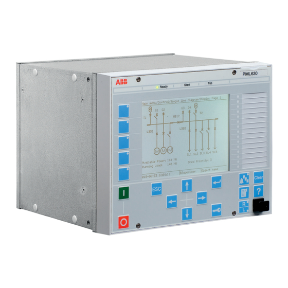
Section 2 1MRS757256 F PML630 overview Download connectivity packages from the ABB Web site http://www.abb.com/substationautomation Local HMI The LHMI is used for setting, monitoring and controlling the device. The LHMI comprises the display, buttons, LED indicators and communication port. GUID-AC825CD8-7361-464F-98DC-35D81332D75F V4 EN... - Page 30 Section 2 1MRS757256 F PML630 overview The display view is divided into four basic areas. GUID-371FF8D7-5C0C-406E-B0CE-F512ADB53FF2 V5 EN Figure 3: Display layout 1 Path 2 Content 3 Status 4 Scroll bar (appears when needed) The function button panel shows on request what actions are possible with the function buttons.
- Page 31 Section 2 1MRS757256 F PML630 overview GUID-ED0CC912-ED59-4270-A3B8-9818FFE300FD V5 EN Figure 4: Function button panel The alarm LED panel shows on request the alarm text labels for the alarm LEDs. GUID-A6E0ECB6-03ED-44FC-AD89-BCE6CB25E5DC V4 EN Figure 5: Alarm LED panel The function button and alarm LED panels are not visible at the same time. Each panel is shown by pressing one of the function buttons or the Multipage button.
-
Page 32: Leds
Section 2 1MRS757256 F PML630 overview 2.4.2 LEDs The LHMI includes three indicators above the display: Ready, Start, and Trip. The load shed start (initiation of power balance calculation) and operate (initiation of load- shed commands) are mapped to LHMI Start and Trip LEDs respectively. There are also 15 matrix programmable alarm LEDs in front of the LHMI. -
Page 33: Web Hmi
Section 2 1MRS757256 F PML630 overview GUID-CDE93DB6-914C-49B6-851D-B67152AD7C2B V2 EN Figure 6: LHMI keypad with object control, navigation and command push buttons and RJ-45 communication port 1...5 Function button Enter Disabled in PML630 Disabled in PML630 Disabled in PML630 Uplink LED Escape Not in use Left... -
Page 34: Command Buttons
Section 2 1MRS757256 F PML630 overview WHMI is disabled by default. To enable the WHMI, select Main menu/Configuration/HMI/Web HMI/Operation via the LHMI. WHMI offers several functions. • Alarm indications and event lists • System supervision • Parameter settings • Measurement display •... -
Page 35: Authorization
Section 2 1MRS757256 F PML630 overview Table 2: Command buttons Name Description Enabling parameter editing. Disabling parameter editing. Writing parameters to the device. Refreshing parameter values. Committing changes to device's non-volatile flash memory. Rejecting changes. Triggering the disturbance recorder manually. Saving the disturbance recording. -
Page 36: Communication
Section 2 1MRS757256 F PML630 overview All changes in user management settings will cause an IED reboot. Communication The IED supports IEC 61850-8-1 standard for communication. This includes MMS communication profile for vertical communication and GOOSE communication profile for horizontal communication. All operational information and controls are available through these profiles. - Page 37 Section 2 1MRS757256 F PML630 overview PML630 Ver.1.2.1 supports ANSI/CN protection relays of the 615 and 620 series, REG615 and RIO600 Ver.1.2 or later in addition to the IEC protection relays mentioned in this section. PML630/Compact Load-Shedding Solution Technical Manual...
-
Page 39: Section 3 Basic Functions
Section 3 1MRS757256 F Basic functions Section 3 Basic functions User authentication 3.1.1 Authority check ATHCHCK 3.1.1.1 Functionality To safeguard the interests of our customers, both the IED and the tools that are accessing the IED are protected by means of authorization handling. The authorization handling of the IED and PCM600 is implemented at both access points to the IED. -
Page 40: Settings
Section 3 1MRS757256 F Basic functions Include at least one user in the UserAdministrator group to be able to write users created in PCM600 to the IED. Authorization handling in the IED At delivery the default user is the SuperUser. No Log on is required to operate the IED until a user has been created with the IED User Management. -
Page 41: Functionality
Section 3 1MRS757256 F Basic functions 3.1.2.2 Functionality Authority status (ATHSTAT) function is an indication function block for user logon activity. 3.1.2.3 Operation principle Authority status (ATHSTAT) function informs about two events related to the IED and the user authorization. •... -
Page 42: Local Human-Machine Interface Lhmi
Section 3 1MRS757256 F Basic functions Local human-machine interface LHMI 3.2.1 Local HMI screen behaviour 3.2.1.1 Settings Table 6: SCREEN Non group settings (basic) Name Values (Range) Unit Step Default Description DisplayTimeout 10 - 120 Local HMI display timeout ContrastLevel -100 - 100 Contrast level for display DefaultScreen... -
Page 43: Signals
Section 3 1MRS757256 F Basic functions 3.2.2.2 Signals Table 7: LHMICTRL Input signals Name Type Default Description CLRLEDS BOOLEAN Input to clear the LCD-HMI LEDs Table 8: LHMICTRL Output signals Name Type Description HMI-ON BOOLEAN Backlight of the LCD display is active RED-S BOOLEAN Red LED on the LCD-HMI is steady... -
Page 44: Operation Principle
Section 3 1MRS757256 F Basic functions Each indication LED on LHMI can be set individually to operate in six different sequences; two as follow type and four as latch type. Two of the latching sequence types are intended to be used as a protection indication system, either in collecting or restarting mode, with reset functionality. - Page 45 Section 3 1MRS757256 F Basic functions positive-edge triggered, not level triggered. This means that even if the button is continuously pressed, the acknowledgment/reset only affects indications active at the moment when the button is first pressed. • Automatic reset • Only indications defined for re-starting mode with the latched sequence type 6 (LatchedReset-S)The can be automatically reset.
- Page 46 Section 3 1MRS757256 F Basic functions Activating signal IEC01000228_2_en.vsd IEC01000228 V2 EN Figure 13: Operating sequence 1 (Follow-S) If inputs for two or more colors are active at the same time to one LED the priority is as described above. An example of the operation when two colors are activated in parallel is shown in Figure Activating...
- Page 47 Section 3 1MRS757256 F Basic functions When a LED is acknowledged, all indications that appear before the indication with higher priority has been reset, are acknowledged, independent of if the low priority indication appeared before or after acknowledgment. In Figure 16 it is shown the sequence when a signal of lower priority becomes activated after acknowledgment has been performed on a higher priority signal.
- Page 48 Section 3 1MRS757256 F Basic functions Activating signal GREEN Activating signal YELLOW Activating signal RED Acknow. IEC09000315-1-en.vsd IEC09000315 V1 EN Figure 18: Operating sequence 3, three colors involved, alternative 2 Sequence 4 (LatchedAck-S-F) This sequence has the same functionality as sequence 3, but steady and flashing light have been alternated.
- Page 49 Section 3 1MRS757256 F Basic functions Activating signal GREEN Activating signal RED Reset IEC09000316_1_en.vsd IEC09000316 V1 EN Figure 20: Operating sequence 5, two colors Sequence 6 (LatchedReset-S) In this mode all activated LEDs, which are set to sequence 6 (LatchedReset-S), are automatically reset at a new disturbance when activating any input signal for other LEDs set to sequence 6 (LatchedReset-S).
- Page 50 Section 3 1MRS757256 F Basic functions Disturbance tRestart Activating signal 1 Activating signal 2 LED 1 LED 2 Automatic reset Manual reset IEC01000239_2-en.vsd IEC01000239 V2 EN Figure 21: Operating sequence 6 (LatchedReset-S), two indications within same disturbance Figure 22 shows the timing diagram for a new indication after tRestart time has elapsed.
- Page 51 Section 3 1MRS757256 F Basic functions Figure 23 shows the timing diagram when a new indication appears after the first one has reset but before tRestart has elapsed. Disturbance tRestart Activating signal 1 Activating signal 2 LED 1 LED 2 Automatic reset Manual...
-
Page 52: Signals
Section 3 1MRS757256 F Basic functions Disturbance tRestart Activating signal 1 Activating signal 2 LED 1 LED 2 Automatic reset Manual reset IEC01000242_2_en.vsd IEC01000242 V2 EN Figure 24: Operating sequence 6 (LatchedReset-S), manual reset 3.2.3.4 Signals Table 9: LEDGEN Input signals Name Type Default... -
Page 53: Settings
Section 3 1MRS757256 F Basic functions 3.2.3.5 Settings Table 12: LEDGEN Non group settings (basic) Name Values (Range) Unit Step Default Description Operation Operation Off/On tRestart 0.0 - 100.0 Defines the disturbance length tMax 0.0 - 100.0 Maximum time for the definition of a disturbance Table 13: GRP1_LED1 Non group settings (basic) -
Page 54: Operation Principle
Section 3 1MRS757256 F Basic functions 3.2.4.3 Operation principle Each output on the FNKEYMD1 - FNKEYMD5 function blocks can be controlled from the LHMI function keys. By pressing a function button on the LHMI, the output status of the actual function block changes. These binary outputs can in turn be used to control other function blocks, for example, switch control blocks, binary I/O outputs etc. -
Page 55: Signals
Section 3 1MRS757256 F Basic functions In this mode the output is high for as long as the setting pulse time. After this time the output returns to “0”. The input attribute is reset when the function block detects it being high and there is no output pulse. -
Page 56: Ied Identifiers Terminalid
Section 3 1MRS757256 F Basic functions Table 17: FNKEYTY1 Non group settings (basic) Name Values (Range) Unit Step Default Description Type Function key type Menu shortcut Control MenuShortcut Main menu Main menu Control Events Measurements Disturbance records Monitoring IED identifiers TERMINALID 3.3.1 Functionality IED identifiers (TERMINALID) function allows the user to identify the individual... -
Page 57: Settings
Section 3 1MRS757256 F Basic functions 3.3.3 Settings Table 18: TERMINALID Non group settings (basic) Name Values (Range) Unit Step Default Description StationName 0 - 18 Station name Station name StationNumber 0 - 99999 Station number ObjectName 0 - 18 Object name Object name ObjectNumber... -
Page 58: Application
Section 3 1MRS757256 F Basic functions 3.5.2 Application The rated system frequency is set in Main menu/Configuration/System in the LHMI and PCM600. 3.5.3 Settings Table 19: PRIMVAL Non group settings (basic) Name Values (Range) Unit Step Default Description Frequency 50.0 - 60.0 10.0 50.0 Rated system frequency... -
Page 59: Settings
Section 3 1MRS757256 F Basic functions 3.6.2 Settings Table 20: BASEPH Non group settings (basic) Name Values (Range) Unit Step Default Description Voltage base Val PP 0.01 - 440.00 0.01 20.00 Voltage base value, phase-to-phase Current base Val Ph 1 - 9999 Current base value, phase S base value 3Ph 0.05 - 1800000.00... -
Page 60: Setting Group Handling Setgrps
Section 3 1MRS757256 F Basic functions from the LHMI or configurable binary inputs, results in a highly adaptable IED that can cope with a variety of system scenarios. 3.7.2 Setting group handling SETGRPS 3.7.2.1 Settings Table 21: SETGRPS Non group settings (basic) Name Values (Range) Unit... -
Page 61: Settings
Section 3 1MRS757256 F Basic functions Table 23: ACTVGRP Output signals Name Type Description GRP1 BOOLEAN Setting group 1 is active GRP2 BOOLEAN Setting group 2 is active GRP3 BOOLEAN Setting group 3 is active GRP4 BOOLEAN Setting group 4 is active SETCHGD BOOLEAN Pulse when setting changed... -
Page 62: Application
Section 3 1MRS757256 F Basic functions ACTIVATE GROUP 4 ACTIVATE GROUP 3 ACTIVATE GROUP 2 ACTIVATE GROUP 1 ACTVGRP IOx-Bly1 Æ ACTGRP1 GRP1 IOx-Bly2 Æ ACTGRP2 GRP2 IOx-Bly3 Æ ACTGRP3 GRP3 IOx-Bly4 Æ GRP4 ACTGRP4 SETCHGD IEC09000063_en_1.vsd IEC09000063 V1 EN Figure 30: Connection of the function to external circuits The above example also includes five output signals, for confirmation of which group... -
Page 63: Signal Matrix For Analog Inputs Smai
Section 3 1MRS757256 F Basic functions Signal matrix for analog inputs SMAI 3.8.1 Functionality Signal matrix for analog inputs function (SMAI), also known as the preprocessor function, processes the analog signals connected to it and gives information about all aspects of the analog signals connected, like the RMS value, phase angle, frequency, harmonic content, sequence components and so on. -
Page 64: Settings
Section 3 1MRS757256 F Basic functions Table 25: SMAI_20_1 Output signals Name Type Description SPFCOUT REAL Number of samples per fundamental cycle from internal DFT reference function AI3P GROUP SIGNAL Grouped three phase signal containing data from inputs 1-4 GROUP SIGNAL Quantity connected to the first analog input GROUP SIGNAL Quantity connected to the second analog input... - Page 65 Section 3 1MRS757256 F Basic functions Table 26: SMAI_20_1 Non group settings (basic) Name Values (Range) Unit Step Default Description GlobalBaseSel 1 - 6 Selection of one of the Global Base Value groups DFTRefExtOut InternalDFTRef InternalDFTRef DFT reference for external output DFTRefGrp1 DFTRefGrp2 DFTRefGrp3...
-
Page 66: Signal Matrix For Analog Inputs Smai_20_2
Section 3 1MRS757256 F Basic functions 3.8.3 Signal matrix for analog inputs SMAI_20_2 SMAI_20_2 BLOCK AI3P REVROT ^GRP2L1 ^GRP2L2 ^GRP2L3 ^GRP2N IEC09000138-2-en.vsd IEC09000138 V2 EN Figure 32: SMAI_20_2 to SMAI_20_12 function block Note that input and output signals on SMAI_20_2 to SMAI_20_12 are the same except for input signals GRPxL1 to GRPxN where x is equal to instance number (2 to 12). -
Page 67: Settings
Section 3 1MRS757256 F Basic functions 3.8.3.2 Settings Only values 1-3 of the parameter GlobalBaseSel should normally be used. The values 1-3 refer to the global base value groups Phase Grp 1, Phase Grp 2 and Phase Grp 3 correspondingly (BASEPH1, BASEPH2 and BASEPH3 in PCM600). -
Page 68: Application
Section 3 1MRS757256 F Basic functions only if the current measuring SMAI is used as a frequency reference for the adaptive DFT. This is not recommended, see the Setting guidelines. 3.8.4 Application Signal matrix for analog inputs function (SMAI), also known as the preprocessor function, processes the analog signals connected to it and gives information about all aspects of the analog signals connected, like the RMS value, phase angle, frequency, harmonic content, sequence components and so on. - Page 69 Section 3 1MRS757256 F Basic functions These DFT reference block settings decide DFT reference for DFT calculations (InternalDFTRef will use fixed DFT reference based on set system frequency. DFTRefGrpn will use DFT reference from the selected group block, when own group selected adaptive DFT reference will be used based on calculated signal frequency from own group.ExternalDFTRef will use reference based on input DFTSPFC.
- Page 70 Section 3 1MRS757256 F Basic functions Example of adaptive frequency tracking Task time group 1 SMAI instance 3 phase group SMAI_20_1:1 SMAI_20_2:1 SMAI_20_3:1 DFTRefGrp7 SMAI_20_4:1 SMAI_20_5:1 SMAI_20_6:1 SMAI_20_7:1 SMAI_20_8:1 SMAI_20_9:1 SMAI_20_10:1 SMAI_20_11:1 SMAI_20_12:1 Task time group 2 SMAI instance 3 phase group SMAI_20_1:2 SMAI_20_2:2 SMAI_20_3:2...
-
Page 71: Measured Value Expander Block Mvexp
Section 3 1MRS757256 F Basic functions SMAI_20_7:1 SMAI_20_1-12:2 BLOCK SPFCOUT BLOCK SPFCOUT DFTSPFC AI3P DFTSPFC AI3P REVROT REVROT ^GRP1L1 ^GRP1L1 ^GRP1L2 ^GRP1L2 ^GRP1L3 ^GRP1L3 ^GRP1N ^GRP1N IEC09000028-2-en.vsd IEC09000028 V2 EN Figure 34: Configuration for using an instance in task time group 1 as DFT reference Assume instance SMAI_20_7:1 in task time group 1 has been selected in the configuration to control the frequency tracking (For the SMAI_20_x task time... -
Page 72: Operation Principle
Section 3 1MRS757256 F Basic functions communication I/O functions (MVGGIO) are provided with measurement supervision functionality. All measured values can be supervised with four settable limits: low-low limit, low limit, high limit and high-high limit. The measure value expander block has been introduced to enable translating the integer output signal from the measuring functions to five binary signals: below low-low limit, below low limit, normal, above high-high limit or above high limit. -
Page 73: Settings
Section 3 1MRS757256 F Basic functions Table 34: MVEXP Output signals Name Type Description HIGHHIGH BOOLEAN Measured value is above high-high limit HIGH BOOLEAN Measured value is between high and high-high limit NORMAL BOOLEAN Measured value is between high and low limit BOOLEAN Measured value is between low and low-low limit LOWLOW... - Page 74 Section 3 1MRS757256 F Basic functions Pulse counter (PCGGIO) function in the IED supports unidirectional incremental counters. That means only positive values are possible. The counter uses a 32 bit format, that is, the reported value is a 32-bit, signed integer with a range 0...+2147483647.
-
Page 75: Application
Section 3 1MRS757256 F Basic functions The NEW_VAL signal is a pulse signal. The signal is set if the counter value was updated since last report. The SCAL_VAL signal consists of scaled value (according to parameter Scale), time and status information. 3.10.4 Application Pulse counter (PCGGIO) function counts externally generated binary pulses, for... -
Page 76: Settings
Section 3 1MRS757256 F Basic functions 3.10.6 Settings Table 37: PCGGIO Non group settings (basic) Name Values (Range) Unit Step Default Description Operation Operation Off/On EventMask NoEvents NoEvents Report mask for analog events from pulse ReportEvents counter CountCriteria RisingEdge Pulse counter criteria RisingEdge Falling edge OnChange... -
Page 77: Fixed Signals Fxdsign
Section 3 1MRS757256 F Basic functions 3.11 Fixed signals FXDSIGN 3.11.1 Function block FXDSIGN INTZERO INTONE INTALONE REALZERO STRNULL ZEROSMPL GRP_OFF IEC09000037.vsd IEC09000037 V1 EN Figure 37: Function block 3.11.2 Functionality The Fixed signals function (FXDSIGN) generates a number of pre-set (fixed) signals that can be used in the configuration of an IED, either for forcing the unused inputs in other function blocks to a certain level/value, or for creating certain logic. -
Page 78: Signals
Section 3 1MRS757256 F Basic functions 3.11.5 Signals Table 41: FXDSIGN Output signals Name Type Description BOOLEAN Boolean signal fixed off BOOLEAN Boolean signal fixed on INTZERO INTEGER Integer signal fixed zero INTONE INTEGER Integer signal fixed one INTALONE INTEGER Integer signal fixed all ones REALZERO REAL... -
Page 79: Reporting
Section 3 1MRS757256 F Basic functions each positive edge of the input respectively. The maximum count-up speed is 10 pulses per second. The maximum counter value is 10000. The counter stops at 10000 and no restart takes places, even if the count exceeds 10000. A mechanism for limiting the number of writings per time period is included in the product to avoid the risk of the flash memory becoming worn out due to too many writings. -
Page 80: Functionality
Section 3 1MRS757256 F Basic functions 3.13.2 Functionality When the Test mode functionality TESTMODE is activated, all the protection functions in the IED are automatically blocked. It is then possible to unblock every function(s) individually from the LHMI to perform the required tests. When leaving TESTMODE, all blockings are removed and the IED resumes normal operation. -
Page 81: Application
Section 3 1MRS757256 F Basic functions to unwanted operations. This is only valid if the IED is put in TEST mode by a binary input, not by LHMI. The TESTMODE function block can be used to automatically block functions when a test handle is inserted in a test switch. -
Page 82: Settings
Section 3 1MRS757256 F Basic functions 3.13.6 Settings Table 45: TESTMODE Non group settings (basic) Name Values (Range) Unit Step Default Description TestMode Test mode in operation (On) or not (Off) EventDisable Event disable during testmode CmdTestBit Command bit for test required or not during testmode 3.14 Disturbance record DRRDRE... -
Page 83: Operation Principle
Section 3 1MRS757256 F Basic functions The Disturbance report function is characterized by great flexibility regarding configuration, starting conditions, recording times, and large storage capacity. A disturbance is defined as an activation of an input to the AxRADR or BxRBDR function blocks, which are set to trigger the disturbance recorder. - Page 84 Section 3 1MRS757256 F Basic functions AxRADR Disturbance Report RDRE Analog signals Trip Value Rec Disturbance Recorder BxRBDR Binary signals Event List Event Recorder Indications IEC09000136-2-en.vsdx IEC09000136 V2 EN Figure 41: Disturbance report functions and related function blocks The whole disturbance report can contain information for a number of recordings, each with the data coming from all the parts mentioned above.
- Page 85 Section 3 1MRS757256 F Basic functions frequency, number of analog and binary channels and recording time. In a 50 Hz system it is possible to record 100 where the maximum recording time is 3.4 seconds. The memory limit does not affect the rest of the disturbance report (Event list, Event recorder, Indications and Trip value recorder).
- Page 86 Section 3 1MRS757256 F Basic functions Disturbance recorder, event recorder and indication function register disturbance data and events during tRecording, the total recording time. The total recording time, tRecording, of a recorded disturbance is: Pre-trigger time + tFault + Post-trigger time or Pre-trigger time + Recording time limit , tRecording = depending on which criterion stops the current disturbance recording Trig point...
- Page 87 Section 3 1MRS757256 F Basic functions A1RADR SMAI GRPNAME AI3P A2RADR AI1NAME GRPINPUT1 External analog AI2NAME GRPINPUT2 signals AI3NAME GRPINPUT3 AI4NAME GRPINPUT4 GRPINPUT5 GRPINPUT6 A3RADR A4RADR INPUT21 INPUT22 INPUT23 Internal analog signals INPUT24 INPUT25 INPUT26 INPUT30 GUID-ECD1F42C-23E5-4B0A-953A-CC6D9FDA1C27 V1 EN Figure 44: Analog input function blocks The external input signals are acquired, filtered and skewed, and after configuration available as an input signal on the AxRADR function block via the SMAI function...
- Page 88 Section 3 1MRS757256 F Basic functions If Operation Ch = "On", waveform (samples) is recorded and reported in graph. The analog signals are presented only in the disturbance recording, but they affect the entire disturbance report when being used as triggers. Binary signals Up to 64 binary signals can be selected to be handled by disturbance report.
-
Page 89: Application
Section 3 1MRS757256 F Basic functions Analog signal trigger All analog signals are available for trigger purposes, whether they are recorded in the disturbance recorder or not. The settings are Over trigger Ch, Under trigger Ch, Over Trg Lev Ch and Under Trg Lev Ch. The check of the trigger condition is based on peak-to-peak values. - Page 90 Section 3 1MRS757256 F Basic functions and so on. This information can also be used when planning for and designing new installations, that is, a disturbance recording can be a part of functional analysis. Disturbance report DRRDRE is always included in the IED. It acquires sampled data of all the selected analog and binary signals connected to the function blocks.
-
Page 91: Signals
Section 3 1MRS757256 F Basic functions 3.14.1.5 Signals Table 46: DRRDRE Output signals Name Type Description DRPOFF BOOLEAN Disturbance report function turned off RECSTART BOOLEAN Disturbance recording started RECMADE BOOLEAN Disturbance recording made CLEARED BOOLEAN All disturbances in the disturbance report cleared MEMUSED BOOLEAN More than 80% of memory used... -
Page 92: Analog Input Signals A1Radr And A2Radr
Section 3 1MRS757256 F Basic functions Table 49: DRRDRE Monitored data channels Name Type Values (Range) Unit Description Under Lev Trg Ch 1 BOOLEAN 0=FALSE Under level trig for analog 1=TRUE channel 1 activated Over Lev Trg Ch 1 BOOLEAN 0=FALSE Over level trig for analog 1=TRUE... -
Page 93: Settings
Section 3 1MRS757256 F Basic functions 3.14.2.3 Settings Setting tables for A1RADR and A2RADR are similar except for channel numbers. • A1RADR, channel01 - channel10 • A2RADR, channel11 - channel20 Table 51: A1RADR Non group settings (basic) Name Values (Range) Unit Step Default... -
Page 94: Analog Input Signals A3Radr And A4Radr
Section 3 1MRS757256 F Basic functions 3.14.3 Analog input signals A3RADR and A4RADR 3.14.3.1 Function block GUID-88FD658F-1A11-4704-B152-F9E0C16C873B V1 EN Figure 46: Function block 3.14.3.2 Signals Input signal tables for A3RADR and A4RADR are similar except for the GRPINPUT number. • A3RADR, INPUT21 - INPUT30 •... -
Page 95: Binary Input Signals Bxrbdr
Section 3 1MRS757256 F Basic functions Table 55: A3RADR Non group settings (advanced) Name Values (Range) Unit Step Default Description Nominal value Ch 21 0.0 - 999999.9 Nominal value for analog channel 21 Under trigger Ch 21 Use under level trigger for analog channel 21 (on) or not (off) -
Page 96: Signals
Section 3 1MRS757256 F Basic functions 3.14.4.2 Signals Input signal tables for B1RBDR - B4RBDR are all similar except for the INPUT number. • B1RBDR, INPUT1 - INPUT16 • B2RBDR, INPUT17 - INPUT32 • B3RBDR, INPUT33 - INPUT48 • B4RBDR, INPUT49 - INPUT64 Table 56: B1RBDR input signals Name... -
Page 97: Technical Data
Section 3 1MRS757256 F Basic functions Table 58: B1RBDR Non group settings (advanced) Name Values (Range) Unit Step Default Description Trigger level 1 Trig on 0 Trig on 1 Trigger on positive Trig on 1 (1) or negative (0) slope for binary input Show indication 1 Hide Hide... -
Page 98: Self Supervision With Internal Event List
Section 3 1MRS757256 F Basic functions 3.15 Self supervision with internal event list 3.15.1 Functionality The Self supervision with internal event list (INTERRSIG and SELFSUPEVLST) function reacts to internal system events generated by the different built-in self- supervision elements. The internal events are saved in an internal event list. 3.15.2 Internal error signals INTERRSIG 3.15.2.1... -
Page 99: Operation Principle
Section 3 1MRS757256 F Basic functions 3.15.4 Operation principle The self-supervision operates continuously. • Normal micro-processor watchdog function. • Checking of digitized measuring signals. • Other alarms, for example hardware and time synchronization. The SELFSUPEVLST function status can be monitored from the LHMI, from the Event Viewer in PCM600 or from a SMS/SCS system. -
Page 100: Internal Signals
Section 3 1MRS757256 F Basic functions LIODEV FAIL >1 LIODEV STOPPED e.g. BIO1- ERROR LIODEV STARTED >1 SW Watchdog Error >1 Internal Fail WDOG STARVED Runtime Exec Error RTE FATAL ERROR >1 File System Error FTF FATAL ERROR RTE APP FAILED Runtime App Error RTE ALL APPS OK GENTS RTC ERROR... - Page 101 Section 3 1MRS757256 F Basic functions they are also called internal signals. The internal signals can be divided into two groups. • Standard signals are always presented in the IED, see Table • Hardware dependent internal signals are collected depending on the hardware configuration, see Table Explanations of internal signals are listed in...
-
Page 102: Run-Time Model
Section 3 1MRS757256 F Basic functions Table 63: Explanations of internal signals Name of signal Reasons for activation Internal Fail This signal is active if one or more of the following internal signals are active; Real Time Clock Error, Runtime App Error, Runtime Exec Error, SW Watchdog Error, File System Error Internal Warning... -
Page 103: Application
Section 3 1MRS757256 F Basic functions ADx_Low Controller ADx_High IEC05000296-3-en.vsd IEC05000296 V3 EN Figure 51: Simplified drawing of A/D converter for the IED. The technique to split the analog input signal into two A/D converter(s) with different amplification makes it possible to supervise the A/D converters under normal conditions where the signals from the two A/D converters should be identical. -
Page 104: Technical Data
Section 3 1MRS757256 F Basic functions Internal events are generated by the built-in supervisory functions. The supervisory functions supervise the status of the various modules in the IED and, in case of failure, a corresponding event is generated. Similarly, when the failure is corrected, a corresponding event is generated. -
Page 105: Time Synchronization Timesynchgen
Section 3 1MRS757256 F Basic functions 3.16.2 Time synchronization TIMESYNCHGEN 3.16.2.1 Settings Table 65: TIMESYNCHGEN Non group settings (basic) Name Values (Range) Unit Step Default Description CoarseSyncSrc Coarse time synchronization source SNTP FineSyncSource Fine time synchronization source SNTP IRIG-B SyncMaster Activate IED as synchronization master SNTP-Server 3.16.3... -
Page 106: Time System, Summer Time Begin Dstbegin
Section 3 1MRS757256 F Basic functions 3.16.4 Time system, summer time begin DSTBEGIN 3.16.4.1 Settings Table 67: DSTBEGIN Non group settings (basic) Name Values (Range) Unit Step Default Description MonthInYear January March Month in year when daylight time starts February March April June... -
Page 107: Time System, Summer Time Ends Dstend
Section 3 1MRS757256 F Basic functions 3.16.5 Time system, summer time ends DSTEND 3.16.5.1 Settings Table 68: DSTEND Non group settings (basic) Name Values (Range) Unit Step Default Description MonthInYear January October Month in year when daylight time ends February March April June... -
Page 108: Time Synchronization Via Irig-B
Section 3 1MRS757256 F Basic functions 3.16.7 Time synchronization via IRIG-B 3.16.7.1 Settings Table 70: IRIG-B Non group settings (basic) Name Values (Range) Unit Step Default Description TimeDomain LocalTime LocalTime Time domain Encoding IRIG-B IRIG-B Type of encoding 1344 1344TZ TimeZoneAs1344 MinusTZ PlusTZ... -
Page 109: Real-Time Clock Operation
Section 3 1MRS757256 F Basic functions Synchronization from a higher level Function Optional synchronization of modules at a lower level IEC09000342-1-en.vsd IEC09000342 V1 EN Figure 53: Synchronization principle A function is said to be synchronized when it periodically receives synchronization messages from a higher level. -
Page 110: Synchronization Alternatives
Section 3 1MRS757256 F Basic functions directly for synchronization, that is, for adjusting the internal clock to obtain zero offset at the next coming time message. • If the synchronization message has an offset that is large compared to the other messages, a spike-filter in the IED removes this time-message. -
Page 111: Application
Section 3 1MRS757256 F Basic functions source like GPS, or local without synchronization. Using a local SNTP server without synchronization as primary or secondary server in a redundant configuration is not recommended. Synchronization via IRIG-B IRIG-B is a protocol used only for time synchronization. A clock can provide local time of the year in this format. -
Page 112: Technical Data
Section 3 1MRS757256 F Basic functions • SNTP • IRIG-B Do not use the MicroSCADA OPC server as a time synchronization source. 3.16.10 Technical data Table 71: Time synchronization, time tagging Function Value Time tagging resolution, events and sampled measurement values 1 ms 3.17 Denial of service... -
Page 113: Signals
Section 3 1MRS757256 F Basic functions 3.17.2.2 Signals Table 72: DOSFRNT Output signals Name Type Description LINKUP BOOLEAN Ethernet link status WARNING BOOLEAN Frame rate is higher than normal state ALARM BOOLEAN Frame rate is higher than throttle state 3.17.2.3 Settings The function does not have any parameters available in LHMI or PCM600. -
Page 114: Denial Of Service, Frame Rate Control For Lan1 Port Doslan1
Section 3 1MRS757256 F Basic functions 3.17.3 Denial of service, frame rate control for LAN1 port DOSLAN1 3.17.3.1 Function block DOSLAN1 LINKUP WARNING ALARM IEC09000134-1-en.vsd IEC09000134 V1 EN Figure 55: Function block 3.17.3.2 Signals Table 74: DOSLAN1 Output signals Name Type Description LINKUP... -
Page 115: Operation Principle
Section 3 1MRS757256 F Basic functions Name Type Values (Range) Unit Description NonIPPackRecNorm INTEGER Number of non IP packets received in normal mode NonIPPackRecPoll INTEGER Number of non IP packets received in polled mode NonIPPackDisc INTEGER Number of non IP packets discarded 3.17.4 Operation principle... -
Page 116: Application
Section 3 1MRS757256 F Basic functions 3.18.3 Application The IEC 61850-8-1 communication protocol allows vertical communication to HSI clients. It allows horizontal communication between two or more IEDs from one or several vendors to exchange information, and to use it in the performance of their functions and for correct co-operation. - Page 117 Section 3 1MRS757256 F Basic functions Engineering Station HSI Workstation Gateway Base System Printer KIOSK 3 KIOSK 1 KIOSK 2 IEC09000135_en.v IEC09000135 V1 EN Figure 56: Example of a communication system with IEC 61850–8–1 Station HSI MicroSCADA Gateway GOOSE Control Protection Control and protection Control...
-
Page 118: Horizontal Communication Via Goose
Section 3 1MRS757256 F Basic functions 3.18.3.1 Horizontal communication via GOOSE GOOSE messages are sent in horizontal communication between the IEDs. The information, which is exchanged, is used for station wide interlocking, breaker failure protection, busbar voltage selection and so on. The simplified principle is shown in Figure 58. - Page 119 Section 3 1MRS757256 F Basic functions IEC08000174.vsd IEC08000174 V1 EN Figure 59: SMT: GOOSE marshalling with Signal Matrix GOOSE receive function blocks extract process information, received by the data set, into single attribute information that can be used within the application configuration. Crosses in the SMT matrix connect received values to the respective function block signal in Signal Matrix.
- Page 120 Section 3 1MRS757256 F Basic functions GUID-45DC6974-4291-4F1B-B59B-738930268E3F V1 EN PML630/Compact Load-Shedding Solution Technical Manual...
-
Page 121: Settings
Section 3 1MRS757256 F Basic functions GUID-CCE35022-C0B7-4F5A-BA9A-36A6E46AAC24 V1 EN Figure 60: SMT: GOOSE receive function block with converted signals 3.18.4 Settings Table 77: IEC61850-8-1 Non group settings (basic) Name Values (Range) Unit Step Default Description Operation Operation Off/On PML630/Compact Load-Shedding Solution Technical Manual... -
Page 122: Technical Data
Section 3 1MRS757256 F Basic functions 3.18.5 Technical data Table 78: IEC 61850-8-1 communication protocol Function Value Protocol IEC 61850-8-1 Communication speed for the IEDs 100BASE-FX Protocol IEC 608–5–103 Communication speed for the IEDs 9600 or 19200 Bd Protocol DNP3.0 Communication speed for the IEDs 300–19200 Bd Protocol... -
Page 123: Settings
Section 3 1MRS757256 F Basic functions Table 80: GOOSEPWRFDRRCV Output signals Name Type Description SPSOUT1 BOOLEAN SPS output 1 SPSDATAVALID1 BOOLEAN Valid data on SPS output 1 SPSCOMMVALID1 BOOLEAN Communication valid for SPS output 1 SPSOUT2 BOOLEAN SPS output 2 SPSDATAVALID2 BOOLEAN Valid data on SPS output 2... -
Page 124: Goose Receive Goosepwrsrcrcv
Section 3 1MRS757256 F Basic functions 3.20 GOOSE receive GOOSEPWRSRCRCV 3.20.1 Function block GOOSEPWRSRCRCV BLOCK SPSOUT1 SPSDATAVALID1 SPSCOMMVALID1 SPSOUT2 SPSDATAVALID2 SPSCOMMVALID2 SPSOUT3 SPSDATAVALID3 SPSCOMMVALID3 SPSOUT4 SPSDATAVALID4 SPSCOMMVALID4 DPSOUT1 DPSDATAVALID1 DPSCOMMVALID1 DPSOUT2 DPSDATAVALID2 DPSCOMMVALID2 MVOUT1 MVDATAVALID1 MVCOMMVALID1 MVOUT2 MVDATAVALID2 MVCOMMVALID2 MVOUT3 MVDATAVALID3 MVCOMMVALID3 MVOUT4... -
Page 125: Signals
Section 3 1MRS757256 F Basic functions 3.20.3 Signals Table 82: GOOSEPWRSRCRCV Input signals Name Type Default Description BLOCK BOOLEAN Block of output signals Table 83: GOOSEPWRSRCRCV Output signals Name Type Description SPSOUT1 BOOLEAN SPS output 1 SPSDATAVALID1 BOOLEAN Valid data on SPS output 1 SPSCOMMVALID1 BOOLEAN Communication valid for SPS output 1... -
Page 126: Settings
Section 3 1MRS757256 F Basic functions Name Type Description MVCOMMVALID5 BOOLEAN Communication valid for MV output 5 MVOUT6 REAL MV output 6 MVDATAVALID6 BOOLEAN Valid data on MV output 6 MVCOMMVALID6 BOOLEAN Communication valid for MV output 6 MVOUT7 REAL MV output 7 MVDATAVALID7 BOOLEAN... -
Page 127: Horizontal Communication Via Goose For Interlocking Gooseintlkrcv
Section 3 1MRS757256 F Basic functions 3.21 Horizontal communication via GOOSE for interlocking GOOSEINTLKRCV 3.21.1 Function block GOOSEINTLKRCV BLOCK ^RESREQ ^RESGRANT ^APP1_OP ^APP1_CL APP1VAL ^APP2_OP ^APP2_CL APP2VAL ^APP3_OP ^APP3_CL APP3VAL ^APP4_OP ^APP4_CL APP4VAL ^APP5_OP ^APP5_CL APP5VAL ^APP6_OP ^APP6_CL APP6VAL ^APP7_OP ^APP7_CL APP7VAL ^APP8_OP... - Page 128 Section 3 1MRS757256 F Basic functions Table 86: GOOSEINTLKRCV Output signals Name Type Description RESREQ BOOLEAN Reservation request RESGRANT BOOLEAN Reservation granted APP1_OP BOOLEAN Apparatus 1 position is open APP1_CL BOOLEAN Apparatus 1 position is closed APP1VAL BOOLEAN Apparatus 1 position is valid APP2_OP BOOLEAN Apparatus 2 position is open...
-
Page 129: Settings
Section 3 1MRS757256 F Basic functions Name Type Description APP13_OP BOOLEAN Apparatus 13 position is open APP13_CL BOOLEAN Apparatus 13 position is closed APP13VAL BOOLEAN Apparatus 13 position is valid APP14_OP BOOLEAN Apparatus 14 position is open APP14_CL BOOLEAN Apparatus 14 position is closed APP14VAL BOOLEAN Apparatus 14 position is valid... -
Page 130: Goose Binary Receive Goosebinrcv
Section 3 1MRS757256 F Basic functions 3.22 Goose binary receive GOOSEBINRCV 3.22.1 Function block GOOSEBINRCV BLOCK ^OUT1 OUT1VAL ^OUT2 OUT2VAL ^OUT3 OUT3VAL ^OUT4 OUT4VAL ^OUT5 OUT5VAL ^OUT6 OUT6VAL ^OUT7 OUT7VAL ^OUT8 OUT8VAL ^OUT9 OUT9VAL ^OUT10 OUT10VAL ^OUT11 OUT11VAL ^OUT12 OUT12VAL ^OUT13 OUT13VAL ^OUT14... -
Page 131: Settings
Section 3 1MRS757256 F Basic functions Name Type Description OUT3VAL BOOLEAN Valid data on binary output 3 OUT4 BOOLEAN Binary output 4 OUT4VAL BOOLEAN Valid data on binary output 4 OUT5 BOOLEAN Binary output 5 OUT5VAL BOOLEAN Valid data on binary output 5 OUT6 BOOLEAN Binary output 6... -
Page 132: Goose Function Block To Receive A Double Point Goosedprcv
Section 3 1MRS757256 F Basic functions 3.23 GOOSE function block to receive a double point GOOSEDPRCV 3.23.1 Function block GOOSEDPRCV BLOCK ^DPOUT DATAVALID COMMVALID TEST IEC10000249-1-en.vsd IEC10000249 V1 EN Figure 65: Function block 3.23.2 Functionality GOOSEDPRCV is used to receive a double point value using IEC61850 protocol via GOOSE. -
Page 133: Settings
Section 3 1MRS757256 F Basic functions Table 92: GOOSEDPRCV Output signals Name Type Description DPOUT INTEGER Double point output DATAVALID BOOLEAN Data valid for double point output COMMVALID BOOLEAN Communication valid for double point output TEST BOOLEAN Test output 3.23.5 Settings Table 93: GOOSEDPRCV Non group settings (basic) -
Page 134: Signals
Section 3 1MRS757256 F Basic functions The input of this GOOSE block must be linked in Signal Matrix by means of a cross to receive the integer values. The implementation for IEC 61850 quality data handling is restricted to a simple level. If quality data validity is GOOD, the DATAVALID output is HIGH. -
Page 135: Goose Function Block To Receive A Measurand Value Goosemvrcv
Section 3 1MRS757256 F Basic functions 3.25 GOOSE function block to receive a measurand value GOOSEMVRCV 3.25.1 Function block GOOSEMVRCV BLOCK ^MVOUT DATAVALID COMMVALID TEST IEC10000251-1-en.vsd IEC10000251 V1 EN Figure 67: Function block 3.25.2 Functionality GOOSEMVRCV is used to receive measured value using IEC61850 protocol via GOOSE. -
Page 136: Settings
Section 3 1MRS757256 F Basic functions Table 98: GOOSEMVRCV Output signals Name Type Description MVOUT REAL Measurand value output DATAVALID BOOLEAN Data valid for measurand value output COMMVALID BOOLEAN Communication valid for measurand value output TEST BOOLEAN Test output 3.25.5 Settings Table 99: GOOSEMVRCV Non group settings (basic) -
Page 137: Functionality
Section 3 1MRS757256 F Basic functions 3.26.2 Functionality The GOOSE receive function block GOOSEINTMVRCV is used for receiving a set of data required for load-shedding and manual load-shedding functionality from an external system/IEDs with the power sources like generators and grid transformers. 3.26.3 Signals Table 100:... -
Page 138: Settings
Section 3 1MRS757256 F Basic functions Name Type Description INSCOMMVALID3 BOOLEAN Communication Valid for INS Output 3 INSOUT4 INTEGER INS output 4 INSDATAVALID4 BOOLEAN Valid data on INS output 4 INSCOMMVALID4 BOOLEAN Communication Valid for INS Output 4 DATAVALID BOOLEAN Data valid COMMVALID BOOLEAN... -
Page 139: Signals
Section 3 1MRS757256 F Basic functions The input of this GOOSE block must be linked in Signal Matrix by means of a cross to receive the binary single point values. The implementation for IEC 61850 quality data handling is restricted to a simple level. -
Page 140: Iec 61850 Generic Communication I/O Function Spggio
Section 3 1MRS757256 F Basic functions 3.28 IEC 61850 generic communication I/O function SPGGIO 3.28.1 Function block SPGGIO BLOCK IEC09000237_en_1.vsd IEC09000237 V1 EN Figure 70: Function block 3.28.2 Functionality IEC61850 generic communication I/O functions (SPGGIO) is used to send one single logical signal to other systems or equipment in the substation. -
Page 141: Sp16Ggio
Section 3 1MRS757256 F Basic functions 3.29 IEC 61850 generic communication I/O functions 16 inputs SP16GGIO 3.29.1 Function block SP16GGIO BLOCK ^IN1 ^IN2 ^IN3 ^IN4 ^IN5 ^IN6 ^IN7 ^IN8 ^IN9 ^IN10 ^IN11 ^IN12 ^IN13 ^IN14 ^IN15 ^IN16 IEC09000238_en_1.vsd IEC09000238 V1 EN Figure 71: Function block 3.29.2... -
Page 142: Signals
Section 3 1MRS757256 F Basic functions 3.29.4 Signals Table 107: SP16GGIO Input signals Name Type Default Description BLOCK BOOLEAN Block of function BOOLEAN Input 1 status BOOLEAN Input 2 status BOOLEAN Input 3 status BOOLEAN Input 4 status BOOLEAN Input 5 status BOOLEAN Input 6 status BOOLEAN... -
Page 143: Iec 61850 Generic Communication I/O Function Mvggio
Section 3 1MRS757256 F Basic functions Name Type Values (Range) Unit Description OUT7 GROUP Output 7 status SIGNAL OUT8 GROUP Output 8 status SIGNAL OUT9 GROUP Output 9 status SIGNAL OUT10 GROUP Output 10 status SIGNAL OUT11 GROUP Output 11 status SIGNAL OUT12 GROUP... -
Page 144: Operation Principle
Section 3 1MRS757256 F Basic functions 3.30.3 Operation principle Upon receiving an analog signal at its input, the IEC61850 generic communication I/ O functions (MVGGIO) give the instantaneous value of the signal and the range, as output values. In the same time, it sends over IEC 61850-8-1 the value, to other IEC 61850 clients in the substation. -
Page 145: Monitored Data
Section 3 1MRS757256 F Basic functions Name Values (Range) Unit Step Default Description MV lLim -5000.00 - 5000.00 xBase 0.01 -800.00 Low limit multiplied with the base prefix (multiplication factor) MV llLim -5000.00 - 5000.00 xBase 0.01 -900.00 Low Low limit multiplied with the base prefix (multiplication factor) MV min -5000.00 - 5000.00... -
Page 146: Operation Principle
Section 3 1MRS757256 F Basic functions 3.31.3 Operation principle Upon receiving the input signals, the IEC 61850 generic communication I/O functions (DPGGIO) function block sends the signals over IEC 61850-8-1 to the equipment or system that requests these signals. To be able to get the signals, PCM600 must be used to define which function block in which equipment or system should receive this information. -
Page 147: Or Function Block
Section 3 1MRS757256 F Basic functions • • LOOPDELAY used to delay the output signal one execution cycle • TIMERSET has pick-up and drop-out delayed outputs related to the input signal; the timer has a settable time delay • • SRMEMORY is a flip-flop that can set or reset an output from two inputs respectively. - Page 148 Section 3 1MRS757256 F Basic functions OR has six inputs and OR20 has 20 inputs. The output OUT has a default value FALSE initially, which suppresses one cycle pulse if the function has been put in the wrong execution order. Connect at least one output to another function block or to a variable for the function to execute correctly.
-
Page 149: Inverter Function Block Inverter
Section 3 1MRS757256 F Basic functions Table 117: OR Output signals Name Type Description BOOLEAN Output signal NOUT BOOLEAN Inverted output signal Table 118: OR20 Output signals Name Type Description BOOLEAN Output NOUT BOOLEAN Inverted output Settings The function does not have any parameters available in LHMI or PCM600. 3.32.1.2 Inverter function block INVERTER Function block... -
Page 150: Pulsetimer Function Block
Section 3 1MRS757256 F Basic functions 3.32.1.3 PULSETIMER function block Function block PULSETIMER INPUT IEC09000291-1-en.vsd IEC09000291 V1 EN Figure 76: Function block Functionality The pulse function can be used, for example for pulse extensions or limiting of operation of outputs. The PULSETIMER has a settable length. Signals Table 121: PULSETIMER Input signals... -
Page 151: Exclusive Or Function Block Xor
Section 3 1MRS757256 F Basic functions Signals Table 124: GATE Input signals Name Type Default Description INPUT BOOLEAN Input signal Table 125: GATE Output signals Name Type Description BOOLEAN Output signal Settings Table 126: GATE Group settings (basic) Name Values (Range) Unit Step Default... -
Page 152: Loop Delay Function Block Loopdelay
Section 3 1MRS757256 F Basic functions Table 128: XOR Output signals Name Type Description BOOLEAN Output signal NOUT BOOLEAN Inverted output signal Settings The function does not have any parameters available in LHMI or PCM600. 3.32.1.6 Loop delay function block LOOPDELAY Function block LOOPDELAY INPUT... -
Page 153: Timer Function Block Timerset
Section 3 1MRS757256 F Basic functions 3.32.1.7 Timer function block TIMERSET Function block TIMERSET INPUT IEC09000290-1-en.vsd IEC09000290 V1 EN Figure 80: Function block Functionality The function block TIMERSET has pick-up and drop-out delayed outputs related to the input signal. The timer has a settable time delay, t. Input tdelay tdelay... -
Page 154: And Function Block
Section 3 1MRS757256 F Basic functions Settings Table 133: TIMERSET Group settings (basic) Name Values (Range) Unit Step Default Description Operation Operation Off/On 0.000 - 90000.000 0.001 0.000 Delay for settable timer n 3.32.1.8 AND function block Function block IEC09000289 V2 EN Figure 82: Function block Functionality... - Page 155 Section 3 1MRS757256 F Basic functions Signals Table 134: AND Input signals Name Type Default Description INPUT1 BOOLEAN Input signal 1 INPUT2 BOOLEAN Input signal 2 INPUT3 BOOLEAN Input signal 3 INPUT4 BOOLEAN Input signal 4 Table 135: AND20 Input signals Name Type Default...
-
Page 156: Set-Reset Memory Function Block Srmemory
Section 3 1MRS757256 F Basic functions Table 137: AND20 Output signals Name Type Description BOOLEAN Output NOUT BOOLEAN Inverted output Settings The function does not have any parameters available in LHMI or PCM600. 3.32.1.9 Set-reset memory function block SRMEMORY Function block SRMEMORY RESET NOUT... -
Page 157: Reset-Set With Memory Function Block Rsmemory
Section 3 1MRS757256 F Basic functions Table 140: SRMEMORY Output signals Name Type Description BOOLEAN Output signal NOUT BOOLEAN Inverted output signal Settings Table 141: SRMEMORY Group settings (basic) Name Values (Range) Unit Step Default Description Memory Operating mode of the memory function 3.32.1.10 Reset-set with memory function block RSMEMORY Function block... -
Page 158: Equality Check For Real Signals Eqr
Section 3 1MRS757256 F Basic functions Table 144: RSMEMORY Output signals Name Type Description BOOLEAN Output signal NOUT BOOLEAN Inverted output signal Settings Table 145: RSMEMORY Group settings (basic) Name Values (Range) Unit Step Default Description Memory Operating mode of the memory function 3.32.1.11 Equality check for real signals EQR Function block... -
Page 159: Equality Check For Integer Signals Eqi
Section 3 1MRS757256 F Basic functions 3.32.1.12 Equality check for integer signals EQI Function block GUID-1E4DCAB8-7969-4E57-A65C-A26406C58649 V1 EN Figure 86: Function block Functionality The EQI function compares the integer inputs INT_IN1 and INT_IN2 and activates the binary output OUTPUT, if INT_IN1 is equal to INT_IN2. If INT_IN1 = INT_IN2, OUTPUT = 1, else OUTPUT = 0. -
Page 160: Greater Than Check For Integer Signals Gti
Section 3 1MRS757256 F Basic functions If REAL_IN1 > REAL_IN2, OUTPUT = 1, else OUTPUT = 0. Logic function blocks do not have the hysteresis feature. Oscillating outputs should be avoided when comparing analog signals that have very closely varying values. Signals Table 150: GTR Input signals... -
Page 161: Greater Than Or Equal Check For Real Signals Ger
Section 3 1MRS757256 F Basic functions Table 153: GTI Output signals Name Type Description OUTPUT BOOLEAN Binary output 3.32.1.15 Greater than or equal check for real signals GER Function block GUID-1D90C1E8-5B94-427A-A19D-69BABBCB34A7 V1 EN Figure 89: Function block Functionality The function compares the real inputs REAL_IN1 and REAL_IN2 and activates the binary output OUTPUT, if REAL_IN1 is greater than or equal to REAL_IN2. -
Page 162: Less Than Check For Real Signals Ltr
Section 3 1MRS757256 F Basic functions Functionality The function compares the integer inputs INT_IN1 and INT_IN2 and activates the binary output OUTPUT, if INT_IN1 is greater than or equal to INT_IN2. If INT_IN1 ≥ INT_IN2, OUTPUT = 1, else OUTPUT = 0. Logic function blocks do not have the hysteresis feature. -
Page 163: Less Than Check For Integer Signals Lti
Section 3 1MRS757256 F Basic functions Signals Table 158: LTR Input signals Name Type Default Description REAL_IN1 REAL Real input 1 REAL_IN2 REAL Real input 2 Table 159: LTR Output signals Name Type Description OUTPUT BOOLEAN Binary output 3.32.1.18 Less than check for integer signals LTI Function block GUID-35D9C6D8-FEAF-4B35-8FCD-8A00AE8E1FBA V1 EN Figure 92:... -
Page 164: Less Than Or Equal Check For Real Signals Ler
Section 3 1MRS757256 F Basic functions 3.32.1.19 Less than or equal check for real signals LER Function block GUID-B38B55AC-0F56-4913-B12D-79A5008B21A2 V1 EN Figure 93: Function block Functionality The function compares the real inputs REAL_IN1 and REAL_IN2 and activates the binary output OUTPUT, if REAL_IN1 is less than or equal to REAL_IN2. If REAL_IN1 ≤... -
Page 165: Not Equal Check For Real Signals Ner
Section 3 1MRS757256 F Basic functions If INT_IN1 ≤ INT_IN2, OUTPUT = 1, else OUTPUT = 0. Logic function blocks do not have the hysteresis feature. Oscillating outputs should be avoided when comparing analog signals that have very closely varying values. Signals Table 164: LEI Input signals... -
Page 166: Not Equal Check For Integer Signals Nei
Section 3 1MRS757256 F Basic functions Table 167: NER Output signals Name Type Description OUTPUT BOOLEAN Binary output 3.32.1.22 Not equal check for integer signals NEI Function block GUID-10E96EE1-8BCF-47AA-AD2F-BDA97D2B332F V1 EN Figure 96: Function block Functionality The function compares the integer inputs INT_IN1 and INT_IN2 and activates the binary output OUTPUT, if INT_IN1 is not equal to INT_IN2. -
Page 167: Orqt Function Block
Section 3 1MRS757256 F Basic functions 3.32.2.1 ORQT function block Function block ORQT INPUT1 INPUT2 NOUT INPUT3 INPUT4 INPUT5 INPUT6 IEC09000298-1-en.vsd IEC09000298 V1 EN Figure 97: Function block Functionality ORQT function block (ORQT) is used to form general combinatory expressions with Boolean variables. -
Page 168: Inverterqt Function Block
Section 3 1MRS757256 F Basic functions 3.32.2.2 INVERTERQT function block Function block INVERTERQT INPUT IEC09000299-1-en.vsd IEC09000299 V1 EN Figure 98: Function block Signals Table 172: INVERTERQT Input signals Name Type Default Description INPUT BOOLEAN Input signal Table 173: INVERTERQT Output signals Name Type Description... -
Page 169: Xorqt Function Block
Section 3 1MRS757256 F Basic functions Signals Table 174: PULSETIMERQT Input signals Name Type Default Description INPUT BOOLEAN Input signal Table 175: PULSETIMERQT Output signals Name Type Description BOOLEAN Output signal Settings Table 176: PULSETIMERQT Non group settings (basic) Name Values (Range) Unit Step... -
Page 170: Settable Timer Function Block Timersetqt
Section 3 1MRS757256 F Basic functions Table 178: XORQT Output signals Name Type Description BOOLEAN Output signal NOUT BOOLEAN Inverted output signal Settings The function does not have any parameters available in LHMI or PCM600. 3.32.2.5 Settable timer function block TIMERSETQT Function block TIMERSETQT INPUT... -
Page 171: Andqt Function Block
Section 3 1MRS757256 F Basic functions Signals Table 179: TIMERSETQT Input signals Name Type Default Description INPUT BOOLEAN Input signal Table 180: TIMERSETQT Output signals Name Type Description BOOLEAN Output signal, pick-up delayed BOOLEAN Output signal, drop-out delayed Settings Table 181: TIMERSETQT Group settings (basic) Name Values (Range) -
Page 172: Set-Reset Function Block Srmemoryqt
Section 3 1MRS757256 F Basic functions Signals Table 182: ANDQT Input signals Name Type Default Description INPUT1 BOOLEAN Input signal 1 INPUT2 BOOLEAN Input signal 2 INPUT3 BOOLEAN Input signal 3 INPUT4 BOOLEAN Input signal 4 Table 183: ANDQT Output signals Name Type Description... -
Page 173: Reset-Set Function Block Rsmemoryqt
Section 3 1MRS757256 F Basic functions Signals Table 185: SRMEMORYQT Input signals Name Type Default Description BOOLEAN Input signal to set RESET BOOLEAN Input signal to reset Table 186: SRMEMORYQT Output signals Name Type Description BOOLEAN Output signal NOUT BOOLEAN Inverted output signal Settings Table 187:... -
Page 174: Invalidqt Function Block
Section 3 1MRS757256 F Basic functions Signals Table 189: RSMEMORYQT Input signals Name Type Default Description BOOLEAN Input signal to set RESET BOOLEAN Input signal to reset Table 190: RSMEMORYQT Output signals Name Type Description BOOLEAN Output signal NOUT BOOLEAN Inverted output signal Settings Table 191:... - Page 175 Section 3 1MRS757256 F Basic functions Inputs are copied to outputs. If input VALID is 0, or if its quality invalid bit is set, all outputs' invalid quality bit is set. The timestamp of an output is set to the latest timestamp of INPUT and VALID input.
-
Page 176: Application
Section 3 1MRS757256 F Basic functions Name Type Description OUTPUT14 BOOLEAN Indication output 14 OUTPUT15 BOOLEAN Indication output 15 OUTPUT16 BOOLEAN Indication output 16 Settings The function does not have any parameters available in LHMI or PCM600. 3.32.3 Application A set of standard logic blocks, like AND or OR, and timers are available for adapting the IED configuration to the specific application needs. -
Page 177: Boolean 16 To Integer Conversion B16I
Section 3 1MRS757256 F Basic functions Table 195: Configurable logic Q/T Logic block Quantity with cycle time Range or value Accuracy medium normal ANDQT INVALIDQT INVERTERQT ORQT PULSETIMERQT (0.000-90000.0 ± 0.5% ± 25 ms 00) s RSMEMORYQT SRMEMORYQT TIMERSETQT (0.000-90000.0 ±... -
Page 178: Signals
Section 3 1MRS757256 F Basic functions 3.33.4 Signals Table 196: B16I Input signals Name Type Default Description BLOCK BOOLEAN Block of function BOOLEAN Input 1 BOOLEAN Input 2 BOOLEAN Input 3 BOOLEAN Input 4 BOOLEAN Input 5 BOOLEAN Input 6 BOOLEAN Input 7 BOOLEAN... -
Page 179: Integer To Boolean 16 Conversion Ib16A
Section 3 1MRS757256 F Basic functions 3.34 Integer to boolean 16 conversion IB16A 3.34.1 Function block IB16A BLOCK OUT1 OUT2 OUT3 OUT4 OUT5 OUT6 OUT7 OUT8 OUT9 OUT10 OUT11 OUT12 OUT13 OUT14 OUT15 OUT16 IEC09000036-1-en.vsd IEC09000036 V1 EN Figure 108: Function block 3.34.2 Functionality... -
Page 180: Settings
Section 3 1MRS757256 F Basic functions Name Type Description OUT5 BOOLEAN Output 5 OUT6 BOOLEAN Output 6 OUT7 BOOLEAN Output 7 OUT8 BOOLEAN Output 8 OUT9 BOOLEAN Output 9 OUT10 BOOLEAN Output 10 OUT11 BOOLEAN Output 11 OUT12 BOOLEAN Output 12 OUT13 BOOLEAN Output 13... -
Page 181: Functionality
Section 3 1MRS757256 F Basic functions 3.35.2.2 Functionality ADDI integer adding block adds the integer inputs INT_IN1 and INT_IN2 together. ADDI executes the equation: INT OUT INT IN INT IN (Equation 1) GUID-2572C1EA-50AF-4C6D-B2EF-99F3BD78DCCF V1 EN 3.35.2.3 Signals Table 201: ADDI Input signals Name Type Default... -
Page 182: Divi Function Block
Section 3 1MRS757256 F Basic functions Table 204: ADDR Output signals Name Type Description REAL_OUT REAL Real output 3.35.4 DIVI function block 3.35.4.1 Function block GUID-B761969D-C7F8-4D25-B6AE-FEBA6F9A112C V1 EN Figure 111: Function block 3.35.4.2 Functionality DIVI integer division block divides the INT_IN1 input by INT_IN2. The output of the division, the module of division INT_OUT_MOD and the validity of integer division in case of division by zero INT_VALID. -
Page 183: Divr Function Block
Section 3 1MRS757256 F Basic functions Table 207: DIVI Output signals Name Type Description INT_OUT INTEGER Integer output INT_VALID BOOLEAN Integer output validity INT_OUT_MOD INTEGER Integer output division modulo 3.35.5 DIVR function block 3.35.5.1 Function block GUID-6B1B85CC-3125-4429-88D9-11EBA237F658 V1 EN Figure 112: Function block 3.35.5.2 Functionality... -
Page 184: Muli Function Block
Section 3 1MRS757256 F Basic functions 3.35.6 MULI function block 3.35.6.1 Function block GUID-D0EA1F48-3533-45D9-8BFF-7A256919D23A V1 EN Figure 113: Function block 3.35.6.2 Functionality MULI integer multiplication block multiplies the integer input INT_IN1 with the INT_IN2 integer input. MULI executes the equation ⋅... -
Page 185: Functionality
Section 3 1MRS757256 F Basic functions 3.35.7.2 Functionality MULR real multiplication block multiplies the real input REAL_IN1 with the real input REAL_IN2. MULR executes the equation: ⋅ 1 REAL OUT REAL IN REAL IN (Equation 7) GUID-2351068B-A88E-40B6-A66C-C519A593321D V1 EN 3.35.7.3 Signals Table 213: MULR Input signals... -
Page 186: Signals
Section 3 1MRS757256 F Basic functions 3.35.8.3 Signals Table 215: SUBI Input signals Name Type Default Description INT_IN1 INTEGER Integer input 1 INT_IN2 INTEGER Integer input 2 Table 216: SUBI Output signals Name Type Description INT_OUT INTEGER Integer output 3.35.9 SUBR function block 3.35.9.1 Function block... -
Page 187: Itor Function Block
Section 3 1MRS757256 F Basic functions 3.35.10 ITOR function block 3.35.10.1 Function block GUID-E281071A-813C-4060-B076-4C79C412DEC4 V1 EN Figure 117: Function block 3.35.10.2 Functionality ITOR integer to real conversion block converts the integer input IN to the real value output OUT. 3.35.10.3 Signals Table 219: ITOR Input signals... -
Page 188: Signals
Section 3 1MRS757256 F Basic functions Table 221: RTOI OUT_VAL logic Value of OUT_VAL Description TRUE Integer conversion valid FALSE Absolute real input size exceeds the maximum integer size 3.35.11.3 Signals Table 222: RTOI Input signals Name Type Default Description REAL Real input Table 223:... -
Page 189: Signals
Section 3 1MRS757256 F Basic functions 3.35.12.3 Signals Table 224: MINMAXR Input signals Name Type Default Description REAL input channel1 REAL input channel2 REAL input channel3 REAL input channel4 REAL input channel5 REAL input channel6 REAL input channel7 REAL input channel8 REAL input channel9 IN10... -
Page 190: Signals
Section 3 1MRS757256 F Basic functions Table 226: SWITCHI output logic CTL_SW FALSE TRUE 3.35.13.3 Signals Table 227: SWITCHI Input signals Name Type Default Description CTL_SW BOOLEAN Control Switch INTEGER Integer input 1 INTEGER Integer input 2 Table 228: SWITCHI Output signals Name Type Description... -
Page 191: Signals
Section 3 1MRS757256 F Basic functions 3.35.14.3 Signals Table 229: SWITCHR Input signals Name Type Default Description CTL_SW BOOLEAN Control Switch REAL Real input 1 REAL Real input 2 Table 230: SWITCHR Output signals Name Type Description REAL Real switch output 3.36 Factory settings restoration In case of configuration data loss or error that prevents the IED from working... -
Page 192: Webserver Function Block
Section 3 1MRS757256 F Basic functions 3.39 WEBSERVER function block Table 233: WEBSERVER Non group settings (basic) Name Values (Range) Unit Step Default Description Operation Operation On/Off Write mode Writing disabled Writing disabled Writing of settings enabled Writing enabled Session timeout 2 - 60 Session timeout PML630/Compact Load-Shedding Solution... -
Page 193: Section 4 Protection Functions
Section 4 1MRS757256 F Protection functions Section 4 Protection functions Multipurpose analog protection MAPGAPC 4.1.1 Identification Function description IEC 61850 IEC 60617 ANSI/IEEE C37.2 identification identification device number Multipurpose analog protection MAPGAPC 4.1.2 Function block GUID-75500106-5F41-4834-9D02-40282D4C7221 V1 EN Figure 122: Function block 4.1.3 Functionality... - Page 194 Section 4 1MRS757256 F Protection functions GUID-FA6A9C14-37BF-4D65-B0CD-A89F359C4EEE V1 EN Figure 123: Functional module diagram Level detector The level detector compares AI_VALUE to the Start value setting. The Operation mode setting defines the direction of the level detector. Table 234: Operation mode types Operation Mode Description "Under"...
-
Page 195: Application
Section 4 1MRS757256 F Protection functions 4.1.5 Application The function block can be used for any general analog signal protection, either underprotection or overprotection. The setting range is wide, allowing various protection schemes for the function. Thus, the absolute hysteresis can be set to a value that suits the application. -
Page 196: Measured Values
Section 4 1MRS757256 F Protection functions Table 238: MAPGAPC Non group settings (basic) Name Values (Range) Unit Step Default Description Operation Operation Off/On Operation mode Over Over Operation mode (1=Over;2=Under) Under Table 239: MAPGAPC Non group settings (advanced) Name Values (Range) Unit Step Default... -
Page 197: Section 5 Supervision Functions
Section 5 1MRS757256 F Supervision functions Section 5 Supervision functions Station battery supervision SPVNZBAT 5.1.1 Identification Function description IEC 61850 IEC 60617 ANSI/IEEE C37.2 identification identification device number Station battery supervision SPVNZBAT U<> U<> 5.1.2 Function block GUID-CB57D54A-0413-4A02-AF8C-C745B2CB8621 V1 EN Figure 124: Function block 5.1.3... - Page 198 Section 5 1MRS757256 F Supervision functions The function execution requires that at least one of the function outputs is connected in configuration. The operation of the station battery supervision function can be described by using a module diagram. All the modules in the diagram are explained in the next sections. GUID-800F5217-5187-4686-8C71-EDB4288A849E V1 EN Figure 125: Functional module diagram...
-
Page 199: Application
Section 5 1MRS757256 F Supervision functions Timer 2 Once activated, the timer activates ST_UHIGH for overvoltage condition. When the operate timer has reached the value set by the Alarm delay time setting, the AL_UHIGH output is activated. If the voltage returns to normal value before the module operates, the reset timer is activated. -
Page 200: Settings
Section 5 1MRS757256 F Supervision functions Table 244: SPVNZBAT Output signals Name Type Description AL_ULOW BOOLEAN Alarm when voltage has been below lower limit for a set time AL_UHIGH BOOLEAN Alarm when voltage has exceeded higher limit for a set time ST_ULOW BOOLEAN Start signal when battery voltage drops below... -
Page 201: Monitored Data
Section 5 1MRS757256 F Supervision functions 5.1.9 Monitored Data Table 248: SPVNZBAT Monitored data Name Type Values (Range) Unit Description U_BATT REAL Service value of the battery terminal voltage AL_ULOW BOOLEAN 0=FALSE Alarm when voltage has 1=TRUE been below lower limit for a set time AL_UHIGH BOOLEAN... -
Page 203: Section 6 Measurement Functions
Section 6 1MRS757256 F Measurement functions Section 6 Measurement functions Three-phase current CMMXU 6.1.1 Identification Function description IEC 61850 IEC 60617 ANSI/IEEE C37.2 identification identification device number Three-phase current measurement CMMXU 6.1.2 Function block GUID-59A05E73-834D-4DF8-818B-F9EAF0392ADB V1 EN Figure 126: Function block 6.1.3 Signals Table 250:... -
Page 204: Settings
Section 6 1MRS757256 F Measurement functions Name Type Description I_INST_B REAL Phase B amplitude, magnitude of instantaneous value I_DB_B REAL Phase B amplitude, magnitude of reported value I_ANGL_B REAL Phase B angle, instantaneous value I_RANGE_B INTEGER Phase B amplitude range I_INST_C REAL Phase C amplitude, magnitude of instantaneous... -
Page 205: Monitored Data
Section 6 1MRS757256 F Measurement functions Name Values (Range) Unit Step Default Description A low limit PhC 0.0 - 100000.0 Low limit (physical value) A low low Lim PhC 0.0 - 100000.0 Low Low limit (physical value) A minimum PhC 0.0 - 100000.0 Minimum value A maximum PhC... -
Page 206: Technical Data
Section 6 1MRS757256 F Measurement functions Name Type Values (Range) Unit Description I_RANGE_B INTEGER 0=Normal Phase B amplitude range 1=High 2=Low 3=High-High 4=Low-Low I_INST_C REAL Phase C amplitude, magnitude of instantaneous value I_DB_C REAL Phase C amplitude, magnitude of reported value I_ANGL_C REAL... -
Page 207: Section 7 Power Management Functions
Section 7 1MRS757256 F Power management functions Section 7 Power management functions Load-shedding Load-shedding functionality ensures the power availability to critical process loads in an industrial network by dropping the less critical loads. Contingency based load- shedding is used as the primary load-shedding function in industrial systems as it is fast and selective in operation. -
Page 208: Load-Shedding Principles And Terminology
Section 7 1MRS757256 F Power management functions If there are no external connections to adjacent electrical network areas, the external connections can be configured as grid transformers. When the electrical network size exceeds the network definition/configuration mentioned earlier, additional PML630 is needed to handle load-shedding for an extended network. - Page 209 Section 7 1MRS757256 F Power management functions Power source Power source Network circuit Bus bar circuit breaker breaker Bus bar Subnetwork 1 Subnetwork 2 Sheddable load GUID-5A408CD0-8288-473B-92F1-18E64A066AAD V1 EN Figure 127: Typical single-line diagram of an electrical network area Figure 128 shows the signal flow diagrams between load-shedding functions.
-
Page 210: Power Flow Sign Conventions
Section 7 1MRS757256 F Power management functions 7.2.1 Power flow sign conventions The power flow sign convention of network circuit breaker in PML630 is considered positive if the power flow direction is from the lower busbar number to the higher busbar number (for example, 1...2 or 2...4 or 1...3), else considered negative. -
Page 211: Compensated Circuit Breaker Status
Section 7 1MRS757256 F Power management functions Table 258: Power flow sign convention for power source Power flow sign convention in Power flow sign convention in Power convention setting power source CB IED PML630 IED Positive XX Power source circuit breaker Busbar Bus bar GUID-337D9722-FF8B-43F6-A154-C0BC2E59597E V1 EN... -
Page 212: Load-Shedding Trigger
Section 7 1MRS757256 F Power management functions NCBDCSWI and LDMMXU for details regarding compensated circuit breaker status calculation. The compensated circuit breaker status has only two states, closed or open, as confirmed. 7.2.3 Load-shedding trigger PML630 performs load-shedding action in an electrical network area due to fast load- shedding trigger, slow load-shedding trigger, external load-shedding trigger input or manual load-shedding trigger. -
Page 213: Manual Load-Shedding Trigger
Section 7 1MRS757256 F Power management functions • Phase overcurrent detection module has operated. • Calculated average demand is violated. • External input is configured and the input gets activated, for example transformer or feeder overcurrent IED (RET/REF630) start signals. If the power flow of the power source is away (that is, power flow direction is negative) from the busbar, slow load-shedding trigger from the respective power source is not initiated. -
Page 214: Load-Shedding Blocking
Section 7 1MRS757256 F Power management functions PML630 performs load-shedding action in its own area, provided that an adjacent PML630 has executed the load-shedding action and the actual shed load is less than required. PML630 receives the load-shedding information from an adjacent PML630 to shed identified loads in its own area. -
Page 215: Power Data Holding And Delay
Section 7 1MRS757256 F Power management functions circuit breaker, the load-shedding is blocked in both associated subnetworks. Load-shedding can also be blocked in all the subnetworks by an external input if configured in LSCACLS. The manual load-shedding action can be performed even though load-shedding is blocked in subnetworks. -
Page 216: Load-Shedding Functions
Section 7 1MRS757256 F Power management functions Load-shedding functions 7.3.1 Power source circuit breaker function PSCSWI • PSCSWI can be configured for generator/external source. • PSCSWI receives the circuit breaker position, island and parallel information of external source, governor mode of generator source and power values of power source. -
Page 217: Contingency Based Load-Shedding Function Lscacls
Section 7 1MRS757256 F Power management functions • NPMMXU controls the modes by which the load-shedding data (that is, spin reserve or extended load-shedding power) can be shared to two adjacent PML630s. • NPMMXU configures the phase overcurrent-based slow load-shedding trigger from continuous to periodic based on the setting. - Page 218 Section 7 1MRS757256 F Power management functions Table 262: Load-shedding priority calculation Load-shedding initiation Shed power calculation Load-shedding priority calculation Fast load-shedding trigger, slow Cumulative shedding power ≥ load-shedding trigger or Power shortfall external trigger Slow load-shedding trigger Cumulative shedding power ≥...
-
Page 219: Load-Shedding Trip Command Function Lsptrc
Section 7 1MRS757256 F Power management functions command is active for a load feeder, provided that the calculated load-shedding priority is less than or equal to the priority setting for the respective load feeder. • When load-shedding priority is calculated with LSCACLS, various subnetwork information required for subnetwork display is latched. -
Page 220: Peer-To-Peer Load-Shedding Function Pplsggio
Section 7 1MRS757256 F Power management functions 7.3.8 Peer-to-peer load-shedding function PPLSGGIO • Each instance of PPLSGGIO receives the data from LSCACLS and NPMMXU. • The individual instances of PPLSGGIO processes the data for an extended load- shedding action. • The individual instance of PPLSGGIO provides outputs for the corresponding load-shedding data of the adjacent network area. -
Page 221: Function Block
Section 7 1MRS757256 F Power management functions 7.4.2 Function block PSCSWI SOURCE CB_COMPS_POS FLS_TRIGGER POWER SLOWLS_OPR CB_POSITION OC_STR CB_SERVICE OC_OPR CB_LOCK_OUT MAX_DMD_ALM CB_IED_QVAL ISLND_PARALL FLS_BLOCK IED_TST_MODE MAX_POWER BLK_BYPASS GOVERNOR_MOD B_SET_CHANGE AP_GOV_QVAL INVAL_CRV ISLAND_PARAL ENA_MULT EXT_OC_SLST INHIBIT_TRG SLS_DISABLE RESET_OC RESET_DEMAND GUID-A7713E52-6998-4D40-9741-34FE541B3CC7 V1 EN Figure 130: Function block 7.4.3... -
Page 222: Operation Principle
Section 7 1MRS757256 F Power management functions 7.4.4 Operation principle The operation of PSCSWI can be described by using a module diagram. All the modules in the diagram are explained in the next sections. POWER MAX_POWER Power GOVERNOR_MOD monitoring AP_GOV_QVAL ISLAND_PARAL FLS_BLOCK B_SET_CHANGE... - Page 223 Section 7 1MRS757256 F Power management functions Table 265: The unit conversion for active power Power convention setting Input Calculated active power Positive W POWER POWER × [0.001] Negative W POWER POWER × [-0.001] Positive kW POWER POWER × [1] Negative kW POWER POWER ×...
-
Page 224: Block Logic
Section 7 1MRS757256 F Power management functions During the power-exporting condition, the available power and active power of the power source can be configured using the Power Cfg export Mod setting. If the Power Cfg export Mod setting is “Pow & Ava Pow Zero” and active power value is negative, the calculated available power and active power values are zero. - Page 225 Section 7 1MRS757256 F Power management functions q = Bad q = Good Load-shedding blocking = TRUE Load-shedding blocking = FALSE GUID-AC44FCB5-C8E0-4CF2-9608-CB82879B1244 V1 EN Figure 132: Logic for load-shedding blocking status at the time of measurement cycle q = Bad q = Good Load-shedding blocking = TRUE Load-shedding blocking = FALSE GUID-82D266F7-DA92-4661-B1BA-8AC28635BD1F V1 EN...
-
Page 226: Compensated Cb Status
Section 7 1MRS757256 F Power management functions 7.4.4.3 Compensated CB status This module calculates the compensated circuit breaker status by considering the circuit breaker position, circuit breaker in service/test status and IED data quality of the power source. The conditions to set the compensated circuit breaker status as TRUE. •... - Page 227 Section 7 1MRS757256 F Power management functions Table 268: Calculation of the FLS_BLOCK and BLK_BYPASS outputs Load-shedding blocking Block override setting BLK_BYPASS output FLS_BLOCK output conditions IED_TST_MODE = IED test mode TRUE FALSE TRUE All yes FALSE TRUE Quality bad CB close Quality bad CB open CB Interm or invalid CB_IED_QVAL = Bad...
-
Page 228: Fast Load Shed Trigger Logic
Section 7 1MRS757256 F Power management functions 7.4.4.5 Fast load shed trigger logic This module calculates the fast load shed trigger to initiate the load-shedding action. Close CB_POSITION Open Intermediate Open CB_LOCK_OUT CB_SERVICE FLS_TRIGGER INHIBIT_TRG Load-shedding blocking (From Block logic module) GUID-45962C27-4CCB-4848-9F22-2B31A9656464 V1 EN Figure 134: Fast load shed trigger logic... - Page 229 Section 7 1MRS757256 F Power management functions The calculated OC_TIME output reflects the timings when the IED receives the input currents. Hence, the actual time of the trigger matches the OC_TIME output only if the current inputs remain the same throughout the duration of the overload. If the input current changes subsequently, the OC_TIME output time also changes correspondingly.
-
Page 230: Demand Based Load Shed
Section 7 1MRS757256 F Power management functions This module inhibits the OC_STR and OC_OPR outputs and slow load-shedding trigger due to external input in any of the following conditions. • The input INHIBIT_TRG is TRUE. • The input SLS_DISABLE is TRUE. •... - Page 231 Section 7 1MRS757256 F Power management functions Active power Linear average demand MAX_DMD_ALM Time( in minutes) GUID-82319A07-E887-4BCA-8FCA-5C03F4A033CC V1 EN Figure 135: Maximum demand scenario-1 Active power Linear average demand MAX_DMD_ALM Time(in minutes) GUID-6141637E-30D7-4056-8A37-C51B9942606F V1 EN Figure 136: Maximum demand scenario-2 Where First active power value Maximum demand setting...
-
Page 232: Slow Load Shed Logic
Section 7 1MRS757256 F Power management functions can be activated either at minute 2 of the maximum demand scenario 1 or at minute 3 of the maximum demand scenario 2. This module inhibits MAX_DMD_ALM output in any of the following conditions. •... - Page 233 Section 7 1MRS757256 F Power management functions If the SLOWLS_OPR output is TRUE, the AVA_POWER output is the same as the Ava power SLS Trg setting, else the AVA_POWER output remains the same as calculated above. The slow load-shedding trigger is inhibited due to any of the following conditions. •...
-
Page 234: Binary To Integer Module
Section 7 1MRS757256 F Power management functions The outputs AVA_POWER and ACTIVE_POWER are reported for the monitoring view. The ACTIVE_POWER (active power), slow load-shedding start and slow load trigger inhibition signals are reported to the Binary to Integer module. 7.4.4.9 Binary to integer module The DATA_SOURCE output provides the load-shedding data for the power source. - Page 235 Section 7 1MRS757256 F Power management functions Bits Bit Description Short name of signal Slow load trigger inhibit status SLS_TRG_BLK External slow load-shedding trigger EXT_SLOW_TRG Compensated CB open status COMP_CB_OPN The Busbar number setting sets the power source load busbar number (BB_NUMBER). The group output SOURCE consists of signals for respective power source which are provided to the NPMMXU function.
-
Page 236: Signals
Section 7 1MRS757256 F Power management functions 7.4.5 Signals Table 271: PSCSWI Input signals Name Type Default Description REAL Phase A RMS current of power source REAL Phase B RMS current of power source REAL Phase C RMS current of power source POWER REAL Active power from power source... -
Page 237: Settings
Section 7 1MRS757256 F Power management functions 7.4.6 Settings Table 273: PSCSWI Group settings (basic) Name Values (Range) Unit Step Default Description Start value 0.05 - 5.00 0.01 0.05 Start value Start value Mult 0.8 - 10.0 Multiplier for scaling the start value Time multiplier 0.05 - 15.00 0.05... - Page 238 Section 7 1MRS757256 F Power management functions Name Values (Range) Unit Step Default Description Slow load shed mode Disable Disable Enable slow load shed trigger of power OC & Ext Trg source Max Dmd Trg OC, Max Dmd, Ext Maximum power SLS 0.0 - 999999.9 Maximum power of source during slow load trigger...
-
Page 239: Measured Values
Section 7 1MRS757256 F Power management functions Name Values (Range) Unit Step Default Description Curve parameter A 0.0086 - 120.0000 0.0001 28.2000 Parameter A for customer programmable curve Curve parameter B 0.0000 - 0.7120 0.0001 0.1217 Parameter B for customer programmable curve Curve parameter C 0.02 - 2.00... -
Page 240: Monitored Data
Section 7 1MRS757256 F Power management functions 7.4.8 Monitored data Table 278: PSCSWI Monitored data Name Type Values (Range) Unit Description DATA_SOURCE INTEGER Load shed data for power source CB_COMPS_POS INTEGER 1=Open Circuit breaker position of 2=Close power source ACTIVE_POWER REAL Active power of power source... -
Page 241: Technical Data
Section 7 1MRS757256 F Power management functions Name Type Values (Range) Unit Description ISLND_PARALL BOOLEAN 1=Parallel Island or parallel mode 0=Island status of external source FLS_BLOCK BOOLEAN 0=FALSE Fast load shed block from 1=TRUE power source BLK_BYPASS BOOLEAN 0=FALSE Block is bypassed 1=TRUE B_SET_CHANGE BOOLEAN... -
Page 242: Function Block
Section 7 1MRS757256 F Power management functions 7.5.2 Function block LDMMXU POWER_L1 CB_POS_L1 L1_CB_COMPS IED_QVAL_L1 L2_CB_COMPS IED_TEST_L1 L3_CB_COMPS EXT_INH_L1 L4_CB_COMPS POWER_L2 L5_CB_COMPS CB_POS_L2 L6_CB_COMPS IED_QVAL_L2 L7_CB_COMPS IED_TEST_L2 L8_CB_COMPS EXT_INH_L2 L9_CB_COMPS POWER_L3 L10_CB_COMPS CB_POS_L3 B_SET_CHANGE IED_QVAL_L3 IED_TEST_L3 EXT_INH_L3 POWER_L4 CB_POS_L4 IED_QVAL_L4 IED_TEST_L4 EXT_INH_L4 POWER_L5... -
Page 243: Operation Principle
Section 7 1MRS757256 F Power management functions priority or inhibit status and power value of each sheddable load is reported to LSCACLS for load-shedding action. 7.5.4 Operation principle The operation of LDMMXU can be described by using a module diagram. All the modules in the diagram are explained in the next sections. -
Page 244: Compensated Cb Status
Section 7 1MRS757256 F Power management functions Table 280: Unit conversion of power for the sheddable load1 Power convention L1 setting Input L1_POWER output POWER_L1 POWER_L1 × [0.001] POWER_L1 POWER_L1 × [1] POWER_L1 POWER_L1 × [1000] 7.5.4.2 Compensated CB status This module calculates the compensated CB status for sheddable load1. -
Page 245: Shed Priority Logic
Section 7 1MRS757256 F Power management functions Cause of inhibition of sheddable load L1_INHIBIT output A = input IED_QVAL_L1 is Bad (within measurement cycle) L1_INHIBIT L1_INHIBIT=”System inhibit” GUID-8449C37E-29B5-4EEF-A469-85ACDDAD2EFD V1 EN A = input IED_QVAL_L1 is Bad (at measurement cycle) L1_INHIBIT L1_INHIBIT=”System inhibit”... -
Page 246: Signals
Section 7 1MRS757256 F Power management functions Table 282: PRIO_L1_5 bits information Bits Bits description 1...5 Sheddable load1 priority 6...10 Sheddable load2 priority 11...15 Sheddable load3 priority 16...20 Sheddable load4 priority 21...25 Sheddable load5 priority Similarly, the priority for each sheddable load that is sheddable load6...10 is represented by consecutive five bits of PRIO_L6_L10. - Page 247 Section 7 1MRS757256 F Power management functions Name Type Default Description IED_QVAL_L3 BOOLEAN Circuit breaker IED quality status of sheddable load3 IED_TEST_L3 BOOLEAN IED test mode behaviour of sheddable load3 EXT_INH_L3 BOOLEAN External inhibit of sheddable load3 POWER_L4 REAL Active power of sheddable load4 CB_POS_L4 INTEGER Circuit breaker position of sheddable load4...
-
Page 248: Settings
Section 7 1MRS757256 F Power management functions Name Type Default Description IED_QVAL_L10 BOOLEAN Circuit breaker IED quality status of sheddable load10 IED_TEST_L10 BOOLEAN IED test mode behaviour of sheddable load10 EXT_INH_L10 BOOLEAN External inhibit of sheddable load10 Table 285: LDMMXU Output signals Name Type Description... - Page 249 Section 7 1MRS757256 F Power management functions Name Values (Range) Unit Step Default Description Priority L6 1 - 19 Load shed priority of sheddable load6 Priority L7 1 - 19 Load shed priority of sheddable load7 Priority L8 1 - 19 Load shed priority of sheddable load8 Priority L9 1 - 19...
-
Page 250: Measured Values
Section 7 1MRS757256 F Power management functions Name Values (Range) Unit Step Default Description Power unit L7 Power unit for sheddable load7 Power unit L8 Power unit for sheddable load8 Power unit L9 Power unit for sheddable load9 Power unit L10 Power unit for sheddable load10 7.5.7 Measured values... - Page 251 Section 7 1MRS757256 F Power management functions Name Type Default Description IED_QVAL_L5 BOOLEAN Circuit breaker IED quality status of sheddable load5 IED_TEST_L5 BOOLEAN IED test mode behaviour of sheddable load5 EXT_INH_L5 BOOLEAN External inhibit of sheddable load5 POWER_L6 REAL Active power of sheddable load6 CB_POS_L6 INTEGER Circuit breaker position of the sheddable load6...
-
Page 252: Monitored Data
Section 7 1MRS757256 F Power management functions 7.5.8 Monitored Data Table 289: LDMMXU Monitored data Name Type Values (Range) Unit Description L1_POWER REAL Active power of the sheddable load1 L1_CB_COMPS INTEGER 1=Open Circuit breaker position of 2=Close sheddable load1 L1_SHED_PRIO INTEGER Shed priority of sheddable load1... - Page 253 Section 7 1MRS757256 F Power management functions Name Type Values (Range) Unit Description L5_INHIBIT INTEGER 2=System Inhibit Load shedding inhibit 0=Not Inhibit status of sheddable load5 1=Operator Inhibit L6_POWER REAL Active power of the sheddable load6 L6_CB_COMPS INTEGER 1=Open Circuit breaker position of 2=Close sheddable load6 L6_SHED_PRIO...
-
Page 254: Network Circuit Breaker Ncbdcswi
Section 7 1MRS757256 F Power management functions Name Type Values (Range) Unit Description L10_INHIBIT INTEGER 2=System Inhibit Load shedding inhibit 0=Not Inhibit status of sheddable 1=Operator load10 Inhibit B_SET_CHANGE BOOLEAN 0=FALSE One or many basic 1=TRUE settings change PRIO_L1_5 INTEGER Shed priority data of sheddable loads 1 to 5 PRIO_L6_10... -
Page 255: Operation Principle
Section 7 1MRS757256 F Power management functions calculates the active power, fast load-shedding trigger, fast load-shedding block and compensated CB status. It has the provision to bypass the fast load-shedding block caused by various conditions. It reports the load-shedding data and active power of network circuit breaker to LSCACLS for load-shedding action. - Page 256 Section 7 1MRS757256 F Power management functions Bus bar Bus bar Sending end circuit breaker GUID-A6CA8B40-4791-4E4E-93B7-1C73D8B82943 V2 EN Figure 141: Bus coupler configuration Bus bar Sending end circuit breaker Receiving end circuit breaker Bus bar GUID-96DFC4D7-7235-411B-A843-15A2922DE558 V2 EN Figure 142: Tie circuit breaker configuration This module converts the units of SND_CB_POWER (sending-end circuit breaker power) and RCV_CB_POWER (receiving-end circuit breaker power) inputs in kW...
-
Page 257: Block Logic
Section 7 1MRS757256 F Power management functions If the CB configuration setting is “Tie breaker” and the CB pow consider setting is “Sending end IED”, the network circuit breaker power is same as the calculated sending-end circuit breaker power. If the CB Configuration setting is “Tie breaker” and the CB pow consider setting is “Receiving end IED”, the network circuit breaker power is same as the calculated receiving-end CB power. - Page 258 Section 7 1MRS757256 F Power management functions Table 291: The calculation of Load shed blocking signal for Bus Coupler configuration CB configuration Conditions Load shed blocking signal setting Bus Coupler A = input SND_IED_QVAL is Bad (Within measurement cycle) Load shed blocking Bus Coupler A = input SND_IED_QVAL is Bad (At measurement At the instance of...
- Page 259 Section 7 1MRS757256 F Power management functions Table 292: The calculation of load shed blocking signal for tie breaker configuration CB configuration CB Pow consider Conditions Load shed blocking signal setting setting Tie breaker Sending end IED A = input SND_IED_QVAL is Receiving end IED Bad or RCV_IED_QVAL is Bad (Within measurement...
-
Page 260: Compensated Circuit Breaker Status
Section 7 1MRS757256 F Power management functions This module processes the network circuit breaker power received from the Power monitoring module based on the load-shedding blocking signals, as shown in Table and the Block override setting. This processed network circuit breaker power is provided by the CB_POWER output for the monitoring view. -
Page 261: Fls Trigger Logic
Section 7 1MRS757256 F Power management functions CB configuration “Bus coupler” SND_CB_POS ”Close” SND_CB_SER SND_IED_QVAL “Good” SND_CB_L_OUT CB configuration “Tie breaker” COMPCB_STS RCV_CB_POS ”Close” RCV_CB_SER RCV_IED_QVAL “Good” RCV_CB_L_OUT GUID-63B0420B-442D-4B34-B4EB-9072CBB27EC1 V1 EN Figure 143: Compensated circuit breaker status logic If the load-shedding blocking signal is active due to IED data quality bad and the Block override setting is set to “Quality bad CB close”, COMPCB_STS is active. -
Page 262: General Logic
Section 7 1MRS757256 F Power management functions The inputs to calculate the fast load-shedding trigger if the CB configuration setting is set to “Bus coupler”. • Sending-end circuit breaker position. • Sending-end lockout operating status. • Sending-end circuit breaker service status. The inputs to calculate the fast load-shedding trigger if the CB configuration setting is set to “Tie breaker”. - Page 263 Section 7 1MRS757256 F Power management functions The FLS_BLOCK output provides the load-shedding blocking signal after considering the override action using the Block override setting. The BLK_BYPASS output indicates the successful overridden action of the load-shedding blocking signal. Table 294: Calculation of FLS_BLOCK and BLK_BYPASS outputs for bus coupler configuration CB Configuration Load-shedding blocking conditions...
-
Page 264: Binary To Integer
Section 7 1MRS757256 F Power management functions CB Configuration Load-shedding blocking conditions Block override setting BLK_BYPASS FLS_BLOCK output setting output Tie breaker SND_CB_POS = Intermediate or Invalid CB Interm or invalid TRUE FALSE RCV_CB_POS = Intermediate or Invalid All yes FALSE TRUE IED test mode... -
Page 265: Signals
Section 7 1MRS757256 F Power management functions The group output NW_CB consists of signals for network circuit breaker which are provided to LSCACLS function. Table 297: Group signals for NW_CB for corresponding instance ofSignal description Group signal description for Signal short name for network NW_CB circuit breaker instance... -
Page 266: Settings
Section 7 1MRS757256 F Power management functions Name Type Description B_SET_CHANGE BOOLEAN One or many basic settings change FLS_BLOCK BOOLEAN Fast load shed block from network CB FLS_TRIGGER BOOLEAN Fast load shed trigger from network CB 7.6.6 Settings Table 300: NCBDCSWI Non group settings (basic) Name Values (Range) -
Page 267: Monitored Data
Section 7 1MRS757256 F Power management functions Name Type Default Description SND_CB_L_OUT BOOLEAN Sending end network CB lockout status SND_IED_QVAL BOOLEAN Sending end CB IED data quality status SND_IED_TEST BOOLEAN Sending end network CB IED test mode behaviour RCV_CB_POWER REAL Receiving end network CB active power RCV_CB_POS INTEGER... -
Page 268: Function Block
Section 7 1MRS757256 F Power management functions 7.7.2 Function block NPMMXU SOURCE1 NW_SOURCE SOURCE2 NW_PPLS1 SOURCE3 NW_PPLS2 TEST_REQUEST SOURCE4 CONFIG_ERROR SOURCE5 SOURCE6 SOURCE7 SOURCE8 SLS_TRG_INH PPLS1_DATA PPLS1_QVAL PPLS1_TEST PPLS2_DATA PPLS2_QVAL PPLS2_TEST TEST GUID-2D1D2979-78F9-49AE-9816-C962CFADE9E3 V1 EN Figure 145: Function block 7.7.3 Functionality The network power monitoring function NPMMXU controls the load-shedding action by processing the load-shed data of various power sources received from the... - Page 269 Section 7 1MRS757256 F Power management functions CONFIG_ERROR Configuration check SOURCE1 SOURCE2 Source1/ SOURCE3 source2 LS SOURCE4 data handle SOURCE5 SOURCE6 SOURCE7 Binary to SOURCE8 integer General logic SLS_TRG_INH NW_SOURCE Busbar logic Power monitoring Load shed sharing mode PPLS1_QVAL PPLS1_DATA Adjacent PPLS2_DATA area LS...
-
Page 270: Configuration Check
Section 7 1MRS757256 F Power management functions 7.7.4.1 Configuration check Based on the configuration of power source 1 and power source 2, the module calculates the configuration check. The configuration check is activated if any of the condition is true. •... -
Page 271: Adjacent Area Ls Data Handle
Section 7 1MRS757256 F Power management functions Table 306: Calculation for ENA_PPLS1 Inputs Signal TEST PPLS1_TEST ENA _PPLS1 FALSE FALSE TRUE FALSE TRUE FALSE TRUE FALSE TRUE TRUE TRUE TRUE The ENA_PPLS1 and ENA_PPLS2 signals are provided to the Power monitoring module, Adjacent area LS data handle module, Source1/source2 LS data handle module and Load shed sharing mode module. -
Page 272: Source1/Source2 Ls Data Handle
Section 7 1MRS757256 F Power management functions • All conditions for processing the must-shedding status hold good. • The overcurrent operate status for power source 1, that is, OC_OPR_SRC1 is FALSE. • The maximum demand operate status for power source 1, that is, MAX_DMD_SRC1 is FALSE. - Page 273 Section 7 1MRS757256 F Power management functions Table 308: Calculation of compensated CB status for power source 1 Setting Grid1 connectivity The calculated Compensated CB status for Power source 1 External source CCB_CLS_SRC1 Peer substation CCB_CLS_SRC1 RCV_CB_STS1 RCV_CB_BLK1 ENA_PPLS1 COMP_CB_SRC1 PPLS1_QVAL Table 309: Calculation of island or parallel status for power source 1...
-
Page 274: Power Monitoring
Section 7 1MRS757256 F Power management functions connectivity setting, PEER2_DATA, PPLS2_QVAL and ENA_PPLS2. The module reports the calculated compensated circuit breaker statuses for power source 1 and power source 2 to the Binary to integer module and Load shed sharing mode module. - Page 275 Section 7 1MRS757256 F Power management functions Based on the Ov Curr Trg interval setting, overcurrent operating statuses of the power sources can be configured to re-trigger the slow load trigger. If the Ov Curr Trg interval setting is zero, slow load-shedding trigger remains active until the overcurrent operating status is activated.
-
Page 276: Load-Shed Sharing Mode
Section 7 1MRS757256 F Power management functions If the fast load-shedding trigger is activated for any power source (power source 1...power source 8), fast load-shedding trigger SRC_FLS_TRG is activated. The busbar number of power sources are represented by BB_NUMBER signal. For example, the BB_NUMBER = 4332121 represents busbar number of power source 1 = 1, busbar number of power source 2 = 2, busbar number of power source 3 = 1, busbar number of power source 4 = 2, busbar number of power source 5 = 3, busbar number... -
Page 277: Busbar Logic
Section 7 1MRS757256 F Power management functions Table 312: Calculation of spinning reserve sharing mode Sl No Condition1 Condition2 SP_RESV_MOD If all the following conditions are satisfied: If all the following conditions are satisfied: 2 (Full-full) • Grid1 connectivity setting is Peer substation. •... -
Page 278: Binary To Integer
Section 7 1MRS757256 F Power management functions The module reports the fast load-shedding blocking, island parallel status, slow load- shedding trigger and slow load-shedding enabling status for busbar 1, busbar 2, busbar 3 and busbar 4 to the Binary to integer module. 7.7.4.9 Binary to integer This module provides the DATA_SOURCE and DATA_LODSHED outputs for the... -
Page 279
Section 7 1MRS757256 F Power management functions The group output NW_SOURCE contains signals which are reported to LSCACLS function. Table 315 shows the group signals for NW_SOURCE. Table 315: Group signals for NW_SOURCE Signal description Group signal NW_SOURCE Fast load-shed blocking for busbar
Bit 1..Bit 4 of DATA_SOURCE Fast load-shed trigger from power sources ... -
Page 280: Signals
Section 7 1MRS757256 F Power management functions Table 317: The group signals for NW_PPLS2 Signal description Group signal NW_PPLS2 Load-shed data of adjacent area connected with power PPLS2_DATA source 2 Fast load-shed CB blocking status for power source 2 CB_BLK_SRC2 Compensated CB open status for power source 2 CCB_OPN_SRC2 7.7.5... -
Page 281: Settings
Section 7 1MRS757256 F Power management functions Table 319: NPMMXU Output signals Name Type Description NW_SOURCE GROUP SIGNAL Group signal of network power sources NW_PPLS1 GROUP SIGNAL GrGroup signal of electrical area connected with power source1 NW_PPLS2 GROUP SIGNAL Group signal of electrical area connected with power source2 AVA_POW_SRC1 REAL... -
Page 282: Monitored Data
Section 7 1MRS757256 F Power management functions Name Type Default Description PPLS2_QVAL BOOLEAN Data quality of electrical area connected with power source2 PPLS2_TEST BOOLEAN Electrical area PML test mode connected with power source2 TEST BOOLEAN Test mode behaviour of PML IED 7.7.8 Monitored data Table 322:... -
Page 283: Function Block
Section 7 1MRS757256 F Power management functions 7.8.2 Function block LSCACLS NW_SOURCE SNW1 NW_CB12 SNW2 NW_CB13 SNW3 NW_CB14 SNW4 NW_CB15 PPLS1 NW_CB16 PPLS2 NW_CB23 LS_OPERATE NW_CB24 LS_START NW_CB25 FLS_OPERATE NW_CB26 FLS_START NW_CB34 SLS_OPERATE NW_CB35 SLS_START NW_CB36 OPERATE_BB1 NW_CB45 OPERATE_BB2 NW_CB46 OPERATE_BB3 NW_CB56 OPERATE_BB4... -
Page 284: Operation Principle
Section 7 1MRS757256 F Power management functions This function also allows the manual load-shedding action that can be executed by the operator based on power or priority. This function generates the trip information for sheddable loads in the corresponding subnetworks based on the calculated load shed priority. This function reports the load shed trip information of individual sheddable loads to the corresponding load shed trip command function LSPTRC This function blocks the load-shedding action in the subnetworks if the load shed... -
Page 285: Network Determination
Section 7 1MRS757256 F Power management functions BLOCK EXT_LS_TRG FLS_COUNTER LS blocking and trigger FLS_CNT_RST NW_SOURCE NW_CB12 NW_CB13 NW_CB14 NW_CB15 NW_CB16 NW_CB23 NW_CB24 NW_CB25 SRC1-8_SN_NO NW_CB26 Network CB12-56_SN_NO determination NW_CB34 BB1-6_SN_NO NW_CB35 LS_START NW_CB36 FLS_START NW_CB45 SLS_START NW_CB46 General LS_OPERATE logic NW_CB56 FLS_OPERATE... -
Page 286
Section 7 1MRS757256 F Power management functions This module receives the compensated circuit breaker status of network CB (i = 1 to 5 and j = 2 to 6 ∀ i
Page 287: Ls Blocking And Trigger
Section 7 1MRS757256 F Power management functions COMP_STS_SRC1...COMP_STS_SRC4 represent the compensated circuit breaker status of power source 1...4 respectively. COMP_STS_SRC1...COMP_STS_SRC3 are TRUE and COMP_STS_SRC3 is FALSE. COMP_STS_CB12, COMP_STS_CB13, COMP_STS_CB24 and COMP_STS_CB34 represent the compensated circuit breaker status of network circuit breakers CB12, CB13, CB24 and CB34 respectively. COMP_STS_CB12 and COMP_STS_CB13 are FALSE.- Page 288 Section 7 1MRS757256 F Power management functions Depending on fast load-shed blocking signals received from NCBDCSWI, NPMMXU functions and subnetwork number of busbars, the load-shed blocking for particular subnetwork is calculated as follows. The module receives the fast load-shed block signal FLS_BLK_BB1...FLS_BLK_BB4 for busbar 1...4 from the NPMMXU function.
- Page 289 Section 7 1MRS757256 F Power management functions The module receives the fast load-shed trigger signals SRC_FLS_TRG from the NPMMXU function and FLS_TRG_CB from the respective NCBDCSWI functions. Figure 153 shows fast load-shed trigger signals for different subnetworks for various conditions. EXT_LS_TRG SRC_FLS_TRG FLS_TRG_CB...
- Page 290 Section 7 1MRS757256 F Power management functions SLS_TRG_SNW1 Subnetwork SLS_TRG_BB1 Slow LS BB1_SN_NO trigger SLS_TRG_SNW2 calculation Subnetwork SLS_TRG_BB4 Slow LS trigger BB4_SN_NO calculation LS_BLOCK1 LS_BLOCK2 SLS_TRG_SNW3 LS_BLOCK3 SLS_TRG_SNW4 LS_BLOCK4 GUID-29E97339-7FA9-4291-A222-C5794C453467 V1 EN Figure 154: Calculation of slow load-shed trigger signal for subnetworks The module receives the slow load-shed enable signals, SLS_ENA_BB1...SLS_ENA_BB4, for busbar 1...4 from NPMMXU function.
- Page 291 Section 7 1MRS757256 F Power management functions SLS_ENA_SNW1 Subnetwork SLS_ENA_BB1 Slow LS SLS_ENA_SNW2 BB1_SN_NO enable calculation SLS_ENA_SNW3 Subnetwork SLS_ENA_BB4 Slow LS enable BB4_SN_NO calculation SLS_ENA_SNW4 GUID-78B5B261-143D-4EB4-AB48-1A66921D0716 V1 EN Figure 155: Calculation of slow load-shed enable signal for subnetworks The module receives the must shed status, RCV_MS_STS1 and RCV_MS_STS2, from NPMMXU function corresponding to adjacent electrical areas connected through power source 1 and power source 2.
Page 292: Load Busbar Monitoring
Section 7 1MRS757256 F Power management functions The fast load-shed blocking signals LS_BLOCK, FLS_TRG_SNW , SLS_TRG_SNW and EXTD_TRG_SNW for each subnetwork are provided to Subnetwork priority calculation module and General logic module. 7.8.4.3 Load busbar monitoring The Load busbar monitoring module calculates the sheddable power corresponding to each priority, total shed load inhibited by system and total shed load inhibited by operator for each subnetwork. - Page 293 Section 7 1MRS757256 F Power management functions • Island-parallel status ISL_PAR_BB1...ISL_PAR_BB4 for busbar 1...4 • Overload amount OV_LOAD_BB1...OV_LOAD_BB4 for busbar 1...4 • Load-shed power RCV_SR_POW1 and RCV_SR_POW2 for adjacent electrical areas • Spinning reserve status RCV_SR_STS1 and RCV_SR_STS2 for adjacent electrical areas •...
- Page 294 Section 7 1MRS757256 F Power management functions The spinning reserve for subnetwork z RCV_SR_POW is same as RCV_LS_POW1 or RCV_LS_POW2 provided spinning reserve status is active for corresponding electrical area. If both power source 1 and power source 2 are in same subnetwork, is the sum of RCV_LS_POW1 and RCV_LS_POW2.
Page 295: Manual Ls Selection
Section 7 1MRS757256 F Power management functions 7.8.4.5 Manual LS selection This module calculates manual load-shed priority and manual load-shed power for each subnetwork. Table 325 shows the manual load-shedding priority and manual load-shedding power calculated for subnetwork z and the MAN_LS_BEH output. Table 325: Calculation of manual LS priority, manual LS power and MAN_LS_BEH output Man load-shed mode...- Page 296 Section 7 1MRS757256 F Power management functions If Enable LS SubNetw1 setting = "Yes", the load-shedding is enabled in the subnetwork 1 and if Enable LS SubNetw1 setting = "No", the load-shedding is disabled in the subnetwork 1. Similarly, Enable LS SubNetw2, Enable LS SubNetw3 and Enable LS SubNetw4 settings are used to enable or disable load-shedding in the subnetwork 2, subnetwork 3 and subnetwork 4 respectively.
- Page 297 Section 7 1MRS757256 F Power management functions Equation 18 shows the calculation of cumulative sheddable load power for each priority p in the subnetwork z. CUM_LOD_PR −1 CUM LOD PR SHD POW SHD POW (Equation 18) GUID-8F768B2B-A06B-4AE7-84EE-C5D86698AB3B V1 EN Where, CUM_LOD_PR = SHD_POW This module calculates the load-shed priority in subnetwork z by comparing the effective load-shed power MAN_SHD_SN
... - Page 298 Section 7 1MRS757256 F Power management functions If multiple load-shed triggers are activated at the same time, the cause of load-shed corresponds to the lowest preference number. If priority-based manual load-shed action is performed along with any other trigger getting activated at the same instance, the cause of load- shed is manual load-shed provided manual load-shed priority is greater than the load-shed priority calculated due to any other trigger for the subnetwork z.
Page 299: Peer Load Shed Logic
Section 7 1MRS757256 F Power management functions The reset acknowledged status, record1 priority, cause of load-shed and load- shedding enabling status for the subnetworks are provided to the General logic module. 7.8.4.7 Peer load shed logic This module receives the must-shedding mode MUST_SHD_MOD and spinning reserve mode SP_RESV_MOD from the NPMMXU function.Page 300: Load Busbar Command
Section 7 1MRS757256 F Power management functions The FLS_START output is TRUE if any of the condition is true. • FLS_TRG_SNW1 is active. • FLS_TRG_SNW2 is active. • FLS_TRG_SNW3 is active. • FLS_TRG_SNW4 is active. If the above conditions are not true, the FLS_START output is FALSE. If the slow load start for power sources is active, the SLS_START output is TRUE else the SLS_START output is FALSE.- Page 301 Section 7 1MRS757256 F Power management functions Table 328: Bits information for LS_OPR_BB1 Bit No Bit description Load-shed operate sheddable load 1 Load-shed operate sheddable load 2 Load-shed operate sheddable load 3 Load-shed operate sheddable load 4 Load-shed operate sheddable load 5 Load-shed operate sheddable load 6 Load-shed operate sheddable load 7 Load-shed operate sheddable load 8...
Page 302: Signals
Section 7 1MRS757256 F Power management functions Signal description Group signal description for SNWLoad mismatch in the subnetwork LOD_MISMATCH Manual load-shed power MAN_SHD_POW Manual load-shed priority MAN_SHD_PRIO Effective power balance in the subnetwork EFF_POW_BAL Effective must-shed power of the subnetwork MUST_SHD_LOD Actual load-shed in the subnetwork ACT_SHD_LOD... - Page 303 Section 7 1MRS757256 F Power management functions Name Type Default Description NW_CB15 GROUP Group signal from network CB connecting BB1 and SIGNAL NW_CB16 GROUP Group signal from network CB connecting BB1 and SIGNAL NW_CB23 GROUP Group signal from network CB connecting BB2 and SIGNAL NW_CB24 GROUP...
- Page 304 Section 7 1MRS757256 F Power management functions Name Type Default Description MAN_POW_SN4 REAL Power in kW for manual load shed in subnetwork 4 MAN_SHD_SN4 BOOLEAN Manual load shed trigger for subnetwork 4 MAN_LS_QVAL BOOLEAN Manual load shed communicated data quality BLOCK BOOLEAN Block for fast load shed and slow load shed...
Page 305: Settings
Section 7 1MRS757256 F Power management functions 7.8.6 Settings Table 333: LSCACLS Non group settings (basic) Name Values (Range) Unit Step Default Description Disable LS SubNetw Disable load-shedding in all subneworks Enable LS SubNetw1 Enable load-shedding in subnetwork 1 Enable LS SubNetw2 Enable load-shedding in subnetwork 2 Enable LS SubNetw3 Enable load-shedding in subnetwork 3...Page 306: Measured Values
Section 7 1MRS757256 F Power management functions 7.8.7 Measured values Table 335: LSCACLS Measured values Name Type Default Description MAN_PRIO_SN1 INTEGER Priority for manual load shed in subnetwork 1 MAN_POW_SN1 REAL Power in kW for manual load shed in subnetwork 1 MAN_SHD_SN1 BOOLEAN Manual load shed trigger for subnetwork 1...- Page 307 Section 7 1MRS757256 F Power management functions Name Type Values (Range) Unit Description B_SET_CHANGE BOOLEAN 0=FALSE One or many basic 1=TRUE settings changed MAN_LS_BEH INTEGER 1=Manual LS Manual load shed disable behaviour 2=Manual Prio setting 3=Manual power setting 4=Communicate priority 5=Communicate power 6=Set Prio...
Page 308: Load-Shed Trip Command Lsptrc
Section 7 1MRS757256 F Power management functions Name Type Values (Range) Unit Description SRC2_SN_NO INTEGER Subnetwork number of source2 SRC3_SN_NO INTEGER Subnetwork number of source3 SRC4_SN_NO INTEGER Subnetwork number of source4 SRC5_SN_NO INTEGER Subnetwork number of source5 SRC6_SN_NO INTEGER Subnetwork number of source6 SRC7_SN_NO INTEGER...Page 309: Function Block
Section 7 1MRS757256 F Power management functions 7.9.2 Function block LSPTRC LBB_OPR_CMD OPR_SL1 OPR_SL2 OPR_SL3 OPR_SL4 OPR_SL5 OPR_SL6 OPR_SL7 OPR_SL8 OPR_SL9 OPR_SL10 GUID-AC4B4338-35D9-46BD-B677-D525DFA61142 V1 EN Figure 158: Function block 7.9.3 Functionality The load-shedding trip command function LSPTRC is the output interface function. Based on the operating input received from LSCACLS, LSPTRC provides the load- shedding trip signals for individual sheddable loads of each load busbar.Page 310: General Logic
Section 7 1MRS757256 F Power management functions 7.9.4.1 General logic Based on the LBB_OPR_CMD input, the general logic calculates the load-shedding trip information for each sheddable load (that is, sheddable load 1, sheddable load 2...sheddable load 10). The OPR_SL1, OPR_SL2…OPR_SL10 outputs provide the load-shedding trip information for sheddable load 1, sheddable load 2...sheddable load10 respectively.Page 311: Measured Values
Section 7 1MRS757256 F Power management functions Name Type Description OPR_SL6 BOOLEAN Operate command for the sheddable load6 OPR_SL7 BOOLEAN Operate command for the sheddable load7 OPR_SL8 BOOLEAN Operate command for the sheddable load8 OPR_SL9 BOOLEAN Operate command for the sheddable load9 OPR_SL10 BOOLEAN Operate command for the sheddable load10...Page 312: Output Interface For Subnetworks Snwrcls
Section 7 1MRS757256 F Power management functions 7.10 Output interface for subnetworks SNWRCLS 7.10.1 Identification Function description IEC 61850 IEC 60617 ANSI/IEEE identification identification identification Subnetwork output SNWRCLS SNWRCLS 7.10.2 Function block SNWRCLS DISABLE_LS SN_ACTIVE LS_BLOCK SLS_TRG_INH NEG_POW_BAL LS_RESET MAN_LS_TRG LS_OPERATE LS_OPR_STS AVA_POWER...- Page 313 Section 7 1MRS757256 F Power management functions CUM_LOD_PR1-19 AVA_POWER RUNNING_LOAD SHDABL_LOAD POWER_BAL LOD_INH_SYS LOD_INH_OPR LOD_MISMATCH MAN_SHD_POW MAN_SHD_PRIO EFF_POW_BAL MUST_SHD_LOD ACT_SHD_LOD LS_OPR_STS DISABLE_LS SN_ACTIVE LS_BLOCK LS_RESET MAN_LS_TRG SHD_PRIO_RC1 SHD_PRIO_RC2 SHD_PRIO_RC3 NEG_POW_BAL LS_OPERATE General DIF_MUST_ACT logic SLS_TRG_INH GUID-D5FEC07E-A8B5-4C08-A435-7D656C9DC858 V2 EN Figure 161: Functional module diagram SNWRCLS receives different load-shedding data of the subnetwork from LSCACLS through the SNW group input.
Page 314: General Logic
Section 7 1MRS757256 F Power management functions Output Load-shedding information LOD_INH_OPR This output provides the total operator inhibited (Manual inhibition) of the sheddable load feeders in the subnetwork. LOD_MISMATCH This output provides the load mismatch in the subnetwork. MAN_SHD_POW This output provides the amount of load to be shed by the operator in the subnetwork during manual load-shed action.Page 315: Signals
Section 7 1MRS757256 F Power management functions Table 343: Load-shedding information of the subnetwork calculated by the General logic module Output Load-shedding information LS_OPERATE If LS_OPR_STS output is Fast Load shed, Slow Load shed, Manual Load shed or Extended Load shed, then the LS_OPERATE output is TRUE, else the LS_OPERATE output is FALSE.Page 316: Monitored Data
Section 7 1MRS757256 F Power management functions Name Type Description DIF_MUST_ACT REAL Difference between the must be load shed and actual load shed MAN_SHD_POW REAL Manual load shed power settings MAN_SHD_PRIO INTEGER Manual load shed Priority settings 7.10.6 Monitored data Table 346: SNWRCLS Monitored data Name...Page 317: Peer-To-Peer Load-Shedding Pplsggio
Section 7 1MRS757256 F Power management functions Name Type Values (Range) Unit Description DIF_MUST_ACT REAL Difference between the must be load shed and actual load shed MAN_SHD_POW REAL Manual load shed power settings LOD_INH_OPR REAL Amount of load inhibited by operator LOD_INH_SYS REAL Amount of load inhibited...Page 318: Function Block
Section 7 1MRS757256 F Power management functions 7.11.2 Function block PPLSGGIO PPLS PEER_CB_STS NW_PPLS PEER_SR_STS PEER_MS_STS PEER_SRC_BLK PEER_SN_BLK PEER_DATA_ER LS_DATA_ER GUID-44A61373-A7B1-43FE-988F-A7DCEA69715C V1 EN Figure 162: Function block 7.11.3 Functionality PPLSGGIO is the output interface for the load-shedding data for an adjacent electrical area connected with the power source.Page 319: General Logic
Section 7 1MRS757256 F Power management functions 7.11.4.1 General logic This module calculates an error signal if the load-shed power of the subnetwork SND_LS_POW exceeds 33554431 kW. This error is indicated by the LS_DATA_ER output. Based on various load shed information, the module calculates the LS_DATA for adjacent electrical area.Page 320: Signals
Section 7 1MRS757256 F Power management functions If PEER_SR_STS is TRUE, the spinning reserve of the adjacent electrical area is provided by PEER_SP_RSV output. If PEER_SR_STS is FALSE, the PEER_SP_RSV output is zero. If PEER_MS_STS is TRUE, the must-shedding power of the adjacent electrical area is provided by PEER_MUST_LS output.- Page 321 Section 7 1MRS757256 F Power management functions Name Type Values (Range) Unit Description PEER_SRC_BLK BOOLEAN 0=FALSE Connectivity and CB 1=TRUE block status of adjacent electrical area PEER_SN_BLK BOOLEAN 0=FALSE Subnetwork LS block 1=TRUE status of adjacent electrical area PEER_DATA_ER BOOLEAN 0=FALSE Data error of adjacent 1=TRUE...
Page 323: Section 8 Control Functions
Section 8 1MRS757256 F Control functions Section 8 Control functions Position evaluation POS_EVAL 8.1.1 Identification Function description IEC 61850 IEC 60617 ANSI/IEEE C37.2 identification identification device number Position evaluation POS_EVAL 8.1.2 Function block POS_EVAL POSITION OPENPOS CLOSEPOS IEC09000079_1_en.vsd IEC09000079 V1 EN Figure 164: POS_EVAL function block 8.1.3...Page 324: Signals
Section 8 1MRS757256 F Control functions Input position (Value) Signal quality Output OPENPOS Output CLOSEPOS 0 (Breaker Good intermediate) 1 (Breaker open) Good 2 (Breaker closed) Good 3 (Breaker faulty) Good Invalid Oscillatory 8.1.5 Signals Table 352: POS_EVAL Input signals Name Type Default...Page 325: Section 9 General Function Block Features
Section 9 1MRS757256 F General function block features Section 9 General function block features Definite time characteristics 9.1.1 Definite time operation The DT mode is enabled when the Operating curve type setting is selected either as "ANSI Def. Time" or "IEC Def. Time". In the DT mode, the OC_OPR (Overcurrent operate) output of the function is activated when the time calculation exceeds the set Operate delay time.- Page 326 Section 9 1MRS757256 F General function block features Operate time limit Operate timer Reset delay time Time Drop-off moment GUID-3BE350A4-B87A-48C8-8DF4-AD5887952FFC V1 EN Figure 166: Operation of the counter in drop-off In case 1, the reset is delayed with the Reset delay time setting and in case 2, the counter is reset immediately, because the Reset delay time setting is set to zero.
- Page 327 Section 9 1MRS757256 F General function block features Timer input OC_STR OC_OPR Reset delay time Reset timer Operate delay time Operate timer GUID-4A7EFE31-446D-43EF-BDEE-E925F2F1C284 V1 EN Figure 167: Drop-off period is longer than the set Reset delay time When the drop-off period is longer than the set Reset delay time, as described in Figure 167, the input signal for the definite timer (here: timer input) is active, provided that the current is above the set Start value.
- Page 328 Section 9 1MRS757256 F General function block features Timer input OC_STR OC_OPR Reset delay time Reset timer Operate delay time Operate timer GUID-172943A9-F4AD-4B8A-A47F-E8BC032EE30D V1 EN Figure 168: Drop-off period is shorter than the set Reset delay time When the drop-off period is shorter than the set Reset delay time, as described in Figure 168, the input signal for the definite timer (here: timer input) is active, provided that the current is above the set Start value.
- Page 329 Section 9 1MRS757256 F General function block features Timer input OC_STR OC_OPR RESET_OC Operate timer Operate delay time GUID-CD88ED62-C826-4D1E-AB3A-ED6BA538163B V1 EN Figure 169: Operating effect of the RESET_OC input INHIBIT_TRG or SLS_DISABLE or load-shedding blocking conditions of power source PSCSWI function can be used to individually block the OC_STR and OC_OPR signals.
Page 330: Current-Based Inverse Definite Minimum Time (Idmt)
Section 9 1MRS757256 F General function block features Timer input OC_STR OC_OPR Operate timer Operate delay time Where, Load shed blocking signal (From Block logic module) INHIBIT_TRG SLS_DISABLE Slow load shed mode “Disable” GUID-E69F65A3-5F47-4CD0-8D85-7AC58244EC44 V1 EN Figure 170: Operating effect of the slow load shed disable signal Activation of INHIBIT_TRG or SLS_DISABLE or load-shed blocking conditions of power source PSCSWI function does not reset the timer...- Page 331 Section 9 1MRS757256 F General function block features The OC_OPR output of the component is activated when the cumulative sum of the integrator calculating the overcurrent situation exceeds the value set by the inverse- time mode. The set value depends on the selected curve type and the setting values used.
Page 332: Standard Inverse-Time Characteristics
Section 9 1MRS757256 F General function block features GUID-E5B35671-200E-4613-9451-F193CE806C2B V1 EN Figure 172: Operate time curves based on IDMT characteristic with the value of the Minimum operate time setting = 1 second 9.2.1.1 Standard inverse-time characteristics For inverse-time operation, both IEC and ANSI/IEEE standardized inverse-time characteristics are supported.- Page 333 Section 9 1MRS757256 F General function block features [ ] = ⋅ − > (Equation 20) GUID-B1368633-DB3A-4922-AB7D-A14F1284C6C9 V1 EN t[s] Operate time in seconds measured current I>...
- Page 334 Section 9 1MRS757256 F General function block features GUID-10FF6657-A539-44E3-B349-FDEB20B203FC V1 EN Figure 173: ANSI extremely inverse-time characteristics PML630/Compact Load-Shedding Solution Technical Manual...
- Page 335 Section 9 1MRS757256 F General function block features GUID-B5B7B2FA-3337-4FC1-922B-49C549C89498 V1 EN PML630/Compact Load-Shedding Solution Technical Manual...
- Page 336 Section 9 1MRS757256 F General function block features Figure 174: ANSI very inverse-time characteristics GUID-D6E1F6E3-69FE-4816-A970-B1E51230831E V1 EN Figure 175: ANSI normal inverse-time characteristics PML630/Compact Load-Shedding Solution Technical Manual...
- Page 337 Section 9 1MRS757256 F General function block features GUID-280097D9-3202-40AB-915F-9CB2FA60F2EE V1 EN Figure 176: ANSI moderately inverse-time characteristics PML630/Compact Load-Shedding Solution Technical Manual...
- Page 338 Section 9 1MRS757256 F General function block features GUID-4D6C2DA6-9D8F-4839-85DD-C0AB970B2AE1 V1 EN Figure 177: ANSI long-time extremely inverse-time characteristics PML630/Compact Load-Shedding Solution Technical Manual...
- Page 339 Section 9 1MRS757256 F General function block features GUID-9E2C691C-D58D-4901-98CE-F16E43BED7FA V1 EN Figure 178: ANSI long-time very inverse-time characteristics PML630/Compact Load-Shedding Solution Technical Manual...
- Page 340 Section 9 1MRS757256 F General function block features GUID-09BDCAC4-F2D6-42B0-827A-41E45F483E91 V1 EN Figure 179: ANSI long-time inverse-time characteristics PML630/Compact Load-Shedding Solution Technical Manual...
- Page 341 Section 9 1MRS757256 F General function block features GUID-A54536C7-77CC-4274-9F9D-FCA4D96E077C V1 EN Figure 180: IEC normal inverse-time characteristics PML630/Compact Load-Shedding Solution Technical Manual...
- Page 342 Section 9 1MRS757256 F General function block features GUID-EB244AA4-E7E4-4DAA-BCC3-2D6417A12BD5 V1 EN Figure 181: IEC very inverse-time characteristics PML630/Compact Load-Shedding Solution Technical Manual...
- Page 343 Section 9 1MRS757256 F General function block features GUID-5213A02A-090C-4435-B871-A15968ACBD4E V1 EN Figure 182: IEC inverse-time characteristics PML630/Compact Load-Shedding Solution Technical Manual...
- Page 344 Section 9 1MRS757256 F General function block features GUID-1DFE4798-F6F5-4372-94E0-DC3C6649A468 V1 EN Figure 183: IEC extremely inverse-time characteristics PML630/Compact Load-Shedding Solution Technical Manual...
- Page 345 Section 9 1MRS757256 F General function block features GUID-E7FA6E7B-66BE-49DA-A8B0-0B43EA407AF0 V1 EN Figure 184: IEC short-time inverse-time characteristics PML630/Compact Load-Shedding Solution Technical Manual...
- Page 346 Section 9 1MRS757256 F General function block features GUID-87145321-935F-4167-8DBB-EEDF16FB2C03 V1 EN Figure 185: IEC long-time inverse-time characteristics PML630/Compact Load-Shedding Solution Technical Manual...
Page 347: User-Programmable Inverse-Time Characteristics
Section 9 1MRS757256 F General function block features 9.2.1.2 User-programmable inverse-time characteristics The user can define curves by entering parameters into the following standard formula. (Equation 22) GUID-775FD6DE-7F45-4112-A154-79F599BBA74F V1 EN t[s] Operate time (in seconds) Curve parameter A Curve parameter B Curve parameter C Curve parameter E Measured current...- Page 348 Section 9 1MRS757256 F General function block features GUID-061E6CD8-FF71-4D8E-B36A-D2A36E98E94F V1 EN Figure 186: RI-type inverse-time characteristics PML630/Compact Load-Shedding Solution Technical Manual...
- Page 349 Section 9 1MRS757256 F General function block features GUID-AAE3BB7C-7CC5-42A7-8CD3-27B050812D7C V1 EN Figure 187: RD-type inverse-time characteristics PML630/Compact Load-Shedding Solution Technical Manual...
Page 350: Reset In Inverse-Time Modes
Section 9 1MRS757256 F General function block features 9.2.2 Reset in inverse-time modes The user can select the reset characteristics by using the Type of reset curve setting. Table 354: Values for reset mode Setting name Possible values Type of reset curve 1=Immediate 2=Def time reset 3=Inverse reset...- Page 351 Section 9 1MRS757256 F General function block features t[s] Reset time (in seconds) Time multiplier Measured current Start value I> Table 355: Coefficients for ANSI delayed inverse reset curves Curve name (1) ANSI Extremely Inverse 29.1 (2) ANSI Very Inverse 21.6 (3) ANSI Normal Inverse 0.46...
- Page 352 Section 9 1MRS757256 F General function block features A070828 V1 EN Figure 188: ANSI extremely inverse reset time characteristics PML630/Compact Load-Shedding Solution Technical Manual...
- Page 353 Section 9 1MRS757256 F General function block features A070829 V1 EN Figure 189: ANSI very inverse reset time characteristics PML630/Compact Load-Shedding Solution Technical Manual...
- Page 354 Section 9 1MRS757256 F General function block features A070830 V1 EN Figure 190: ANSI normal inverse reset time characteristics PML630/Compact Load-Shedding Solution Technical Manual...
- Page 355 Section 9 1MRS757256 F General function block features A070831 V1 EN Figure 191: ANSI moderately inverse reset time characteristics PML630/Compact Load-Shedding Solution Technical Manual...
- Page 356 Section 9 1MRS757256 F General function block features A070832 V1 EN Figure 192: ANSI long-time extremely inverse reset time characteristics PML630/Compact Load-Shedding Solution Technical Manual...
- Page 357 Section 9 1MRS757256 F General function block features A070833 V1 EN Figure 193: ANSI long-time very inverse reset time characteristics PML630/Compact Load-Shedding Solution Technical Manual...
- Page 358 Section 9 1MRS757256 F General function block features A070834 V1 EN Figure 194: ANSI long-time inverse reset time characteristics The delayed inverse-time reset is not available for IEC-type inverse time curves. User-programmable delayed inverse reset PML630/Compact Load-Shedding Solution Technical Manual...
- Page 359 Section 9 1MRS757256 F General function block features The user can define the delayed inverse reset time characteristics with the following formula using the set Curve parameter D. [ ] = ⋅ ...
Page 361: Section 10 Device's Physical Connections
Section 10 1MRS757256 F Device's physical connections Section 10 Device's physical connections 10.1 Protective earth connections The IED shall be earthed with a 16.0 mm flat copper cable. The earth lead should be as short as possible, distance to nearest eartning point shall be less than 1500 mm.Page 362: Inputs
Section 10 1MRS757256 F Device's physical connections 10.2 Inputs 10.2.1 Measuring inputs Each terminal for CTs/VTs is dimensioned for one wire of 0.5...6.0 mm or for two wires of maximum 2.5 mm Table 356: PML630 modules Terminal AIMA01A AIMA05A 1KHL178083R0008 1KHL178083R0013 X101-1, 2 X101-3, 4...Page 363: Binary Inputs
Section 10 1MRS757256 F Device's physical connections 10.2.3 Binary inputs The binary inputs can be used, for example, for status indications, to generate a blocking signal, to unlatch output contacts, to trigger the disturbance recorder or for remote control of IED settings. Each signal connector terminal is dimensioned for one 0.5...2.5 mm wire or for two 0.5...1.0 mm...Page 364: Outputs
Section 10 1MRS757256 F Device's physical connections 10.3 Outputs 10.3.1 The IRF contact functions as a change-over output contact for the self-supervision system of the IED. Under normal operating conditions, the IED is energized and one of the two contacts is closed. When a fault is detected by the self-supervision system or the auxiliary voltage is disconnected, the closed contact drops off and the other contact closes.Page 365: Ethernet Connection For Station Communication
Section 10 1MRS757256 F Device's physical connections • PCM600 • LHMI • WHMI The default IP address of the IED through this port is 192.168.0.254. The front port supports TCP/IP protocol. A standard Ethernet CAT 5 crossover cable is used with the front port. If IED is ordered without LHMI then LAN1 port has to be used for configuration and setting purposes.Page 366: Terminal Diagrams
Section 10 1MRS757256 F Device's physical connections 10.5 Terminal diagrams PML630 PML630 GUID-08E1236F-9950-419F-96D1-EF92AAD1A9D9 V3 EN GUID-AE84E3A7-635E-4758-98D2-35E6038422D0 V1 EN Figure 196: PML630 terminal diagram (4 CT, 5 VT) Figure 197: PML630 terminal diagram (8 CT, 2 VT) PML630/Compact Load-Shedding Solution Technical Manual...Page 367: Section 11 Technical Data
Section 11 1MRS757256 F Technical data Section 11 Technical data Table 362: Dimensions of the IED - half 19" rack Description Value Width 220 mm Height 177 mm Depth 249.5 mm Weight box 6.2 kg Weight LHMI 1.0 kg Table 363: Power supply Description 600PSM03...- Page 368 Section 11 1MRS757256 F Technical data Table 364: Energizing inputs Description Value Rated frequency 50/60 Hz Operating range Rated frequency ± 5 Hz Current inputs Rated current, I 0.1/0.5 A 1/5 A Thermal withstand capability: • Continuously 20 A • For 1 s 100 A 500 A...
- Page 369 Section 11 1MRS757256 F Technical data threshold should be set so that the correct operation is not jeopardized in case of undervoltage of the auxiliary voltage. Table 366: Signal output and IRF output Description Value Rated voltage 250 V AC/DC Continuous contact carry Make and carry for 3.0 s 10 A...
- Page 370 Section 11 1MRS757256 F Technical data Table 371: Degree of protection of flush-mounted device Description Value Front side IP 40 Rear side, connection terminals IP 20 Table 372: Degree of protection of the LHMI Description Value Front and side IP 42 Table 373: Environmental conditions Description...
Page 371: Section 12 Device And Functionality Tests
Section 12 1MRS757256 F Device and functionality tests Section 12 Device and functionality tests Table 375: Electromagnetic compatibility tests Description Type test value Reference 100 kHz and 1 MHz burst IEC 61000-4-18, level 3 disturbance test IEC 60255-22-1 • Common mode 2.5 kV •...- Page 372 Section 12 1MRS757256 F Device and functionality tests Description Type test value Reference • 1...3 s 1000 A/m • Continuous 300 A/m Pulse magnetic field immunity 1000 A/m IEC 61000-4-9 test 6.4/16 µs Damped oscillatory magnetic IEC 61000-4-10 field immunity test •...
- Page 373 Section 12 1MRS757256 F Device and functionality tests Description Type test value Reference • Test voltage 5 kV, 1.2/50 μs, 0.5 J 1 kV, 1.2/50 μs, 0.5 J, communication Insulation resistance IEC 60255-5 measurements IEC 60255-27 • Isolation resistance >100 MΏ, 500 V DC Protective bonding resistance IEC 60255-27 •...
Page 375: Section 13 Applicable Standards And Regulations
Section 13 1MRS757256 F Applicable standards and regulations Section 13 Applicable standards and regulations EN 60255-1 EN 60255-26 EN 60255-27 EMC council directive 2004/108/EC EU directive 2002/96/EC/175 IEC 60255 Low-voltage directive 2006/95/EC IEC 61850 PML630/Compact Load-Shedding Solution Technical Manual...Page 377: Section 14 Glossary
Section 14 1MRS757256 F Glossary Section 14 Glossary 100BASE-FX A physical medium defined in the IEEE 802.3 Ethernet standard for local area networks (LANs) that uses fiber optic cabling 100BASE-TX A physical medium defined in the IEEE 802.3 Ethernet standard for local area networks (LANs) that uses twisted- pair cabling category 5 or higher with RJ-45 connectors 1.- Page 378 Section 14 1MRS757256 F Glossary Human-system interface Input/output IDMT Inverse definite minimum time International Electrotechnical Commission IEC 61850 International standard for substation communication and modeling IEC 61850-8-1 A communication protocol based on the IEC 61850 standard series Intelligent electronic device Internet protocol 1.
- Page 379 Section 14 1MRS757256 F Glossary Station control system SMAI Signal matrix analog input 1. Short Message Service 2. Station monitoring system Signal Matrix tool in PCM600 SNTP Simple Network Time Protocol Connector type for glass fiber cable Software TCP/IP Transmission Control Protocol/Internet Protocol Transformer input module Transmit/Transmitted Wide area network...
- Page 380 — ABB Distribution Solutions Distribution Automation P.O. Box 699 FI-65101 VAASA, Finland Phone +358 10 22 11 www.abb.com/mediumvoltage www.abb.com/relion © Copyright 2019 ABB. All rights reserved.