ABB Relion 630 Series Operation Manual
Protection and control
Hide thumbs
Also See for Relion 630 Series:
- Technical manual (380 pages) ,
- Communication protocol manual (304 pages) ,
- Engineering manual (156 pages)

Related Manuals for ABB Relion 630 Series


Summary of Contents for ABB Relion 630 Series
- Page 1 — RELION® PROTECTION AND CONTROL 630 series Operation Manual...
- Page 3 Document ID: 1MRS756509 Issued: 2019-02-25 Revision: E Product version: 1.3 © Copyright 2019 ABB. All rights reserved...
- Page 4 Copyright This document and parts thereof must not be reproduced or copied without written permission from ABB, and the contents thereof must not be imparted to a third party, nor used for any unauthorized purpose. The software or hardware described in this document is furnished under a license and may be used, copied, or disclosed only in accordance with the terms of such license.
- Page 5 In case any errors are detected, the reader is kindly requested to notify the manufacturer. Other than under explicit contractual commitments, in no event shall ABB be responsible or liable for any loss or damage resulting from the use of this manual or the application of the equipment.
- Page 6 (EMC Directive 2004/108/EC) and concerning electrical equipment for use within specified voltage limits (Low-voltage directive 2006/95/EC). This conformity is the result of tests conducted by ABB in accordance with the product standards EN 50263 and EN 60255-26 for the EMC directive, and with the product standards EN 60255-1 and EN 60255-27 for the low voltage directive.
- Page 7 Safety information Dangerous voltages can occur on the connectors, even though the auxiliary voltage has been disconnected. Non-observance can result in death, personal injury or substantial property damage. Only a competent electrician is allowed to carry out the electrical installation. National and local electrical safety regulations must always be followed.
-
Page 9: Table Of Contents
Table of contents Table of contents Section 1 Introduction...............5 This manual..................5 Intended audience................5 Product documentation...............6 Product documentation set............6 Document revision history............. 6 Related documentation..............7 Symbols and conventions..............7 Symbols..................7 Document conventions..............7 Functions, codes and symbols............8 Section 2 Environmental aspects........... 13 Sustainable development.............. - Page 10 Table of contents Selecting local or remote use............35 Identifying the device..............36 Adjusting the display contrast............37 Changing the local HMI language..........37 Navigating in the menu..............38 Menu structure............... 38 Scrolling the display............... 39 Changing the default view............39 Using function buttons..............39 Using the single-line diagram............
- Page 11 Table of contents Settings for relay functionality............63 Settings for different operating conditions........64 Section 6 Operating procedures.............65 Monitoring..................65 Indications................... 65 Using auto-indication messages..........65 Monitoring alarm data.............66 Monitoring an internal IED fault ..........68 Monitoring condition monitoring data........68 Measured and calculated values..........68 Using the local HMI or Web HMI for monitoring.....
- Page 12 Table of contents Factory settings restoration............87 Changing and setting the password..........87 Identifying IED application problems........... 87 Inspecting the wiring...............88 Inspecting the RTD wiring............91 Section 8 Glossary................. 97 630 series Operation Manual...
-
Page 13: Section 1 Introduction
Section 1 1MRS756509 E Introduction Section 1 Introduction This manual The operation manual contains instructions on how to operate the protection relay once it has been commissioned. The manual provides instructions for monitoring, controlling and setting the relay. The manual also describes how to identify disturbances and how to view calculated and measured power grid data to determine the cause of a fault. -
Page 14: Product Documentation
Commissioning manual GUID-C8721A2B-EEB9-4880-A812-849E1A42B02C V1 EN Figure 1: The intended use of documents during the product life cycle Product series- and product-specific manuals can be downloaded from the ABB Web site http://www.abb.com/relion. 1.3.2 Document revision history Document revision/date Product series version... -
Page 15: Related Documentation
Introduction Download the latest documents from the ABB Web site http://www.abb.com/substationautomation. 1.3.3 Related documentation Product series- and product-specific manuals can be downloaded from the ABB Web site http://www.abb.com/substationautomation. Symbols and conventions 1.4.1 Symbols The electrical warning icon indicates the presence of a hazard which could result in electrical shock. -
Page 16: Functions, Codes And Symbols
Section 1 1MRS756509 E Introduction • Abbreviations and acronyms are spelled out in the glossary. The glossary also contains definitions of important terms. • Push button navigation in the LHMI menu structure is presented by using the push button icons. To navigate between the options, use •... - Page 17 Section 1 1MRS756509 E Introduction Description IEC 61850 IEC 60617 ANSI Non-directional earth-fault EFHPTOC I0>> 51N-2 protection, high stage Non-directional earth-fault EFIPTOC I0>>> 50N/51N protection, instantaneous stage Directional earth-fault protection, DEFLPDEF I0> -> 67N-1 low stage Directional earth-fault protection, DEFHPDEF I0>>...
- Page 18 Section 1 1MRS756509 E Introduction Description IEC 61850 IEC 60617 ANSI Stabilized differential protection for machines MPDIF 3dI>G/M 87G/87M Three-phase overvoltage PHPTOV 3U> protection Three-phase undervoltage PHPTUV 3U< protection Positive-sequence overvoltage PSPTOV U1> 47O+ protection Positive-sequence undervoltage PSPTUV U1< 47U+ protection Negative-sequence overvoltage NSPTOV...
- Page 19 Section 1 1MRS756509 E Introduction Description IEC 61850 IEC 60617 ANSI Circuit breaker/disconnector GNRLCSWI I <-> O CB/DC I <-> O CB/DC control Circuit breaker DAXCBR I <-> O CB I <-> O CB Disconnector DAXSWI I <-> O DC I <->...
- Page 20 Section 1 1MRS756509 E Introduction Description IEC 61850 IEC 60617 ANSI Three-phase voltage measurement VPHMMXU 3Upe 3Upe (phase-to-earth) Three-phase voltage measurement VPPMMXU 3Upp 3Upp (phase-to-phase) Residual current measurement RESCMMXU Residual voltage measurement RESVMMXU Power monitoring with P, Q, S, PWRMMXU power factor, frequency Sequence current measurement CSMSQI...
-
Page 21: Section 2 Environmental Aspects
Section 2 1MRS756509 E Environmental aspects Section 2 Environmental aspects Sustainable development Sustainability has been taken into account from the beginning of the product design including the pro-environmental manufacturing process, long life time, operation reliability and disposing of the protection relay. The choice of materials and the suppliers have been made according to the EU RoHS directive (2002/95/EC). - Page 22 Section 2 1MRS756509 E Environmental aspects Table 3: Materials of the protection relay parts Protection relay Parts Material Unit Metallic plates, parts and screws Steel Plastic parts , LCP LHMI display module Various Package Cardboard Attached material Manuals Paper 1) Polycarbonate 2) Liquid crystal polymer 630 series Operation Manual...
-
Page 23: Section 3 630 Series Overview
® 630 series is a part of ABB’s Relion product family. The 630 protection and control product series is characterized by functional scalability and flexible configurability. It also features necessary control functions for bay control in different applications. -
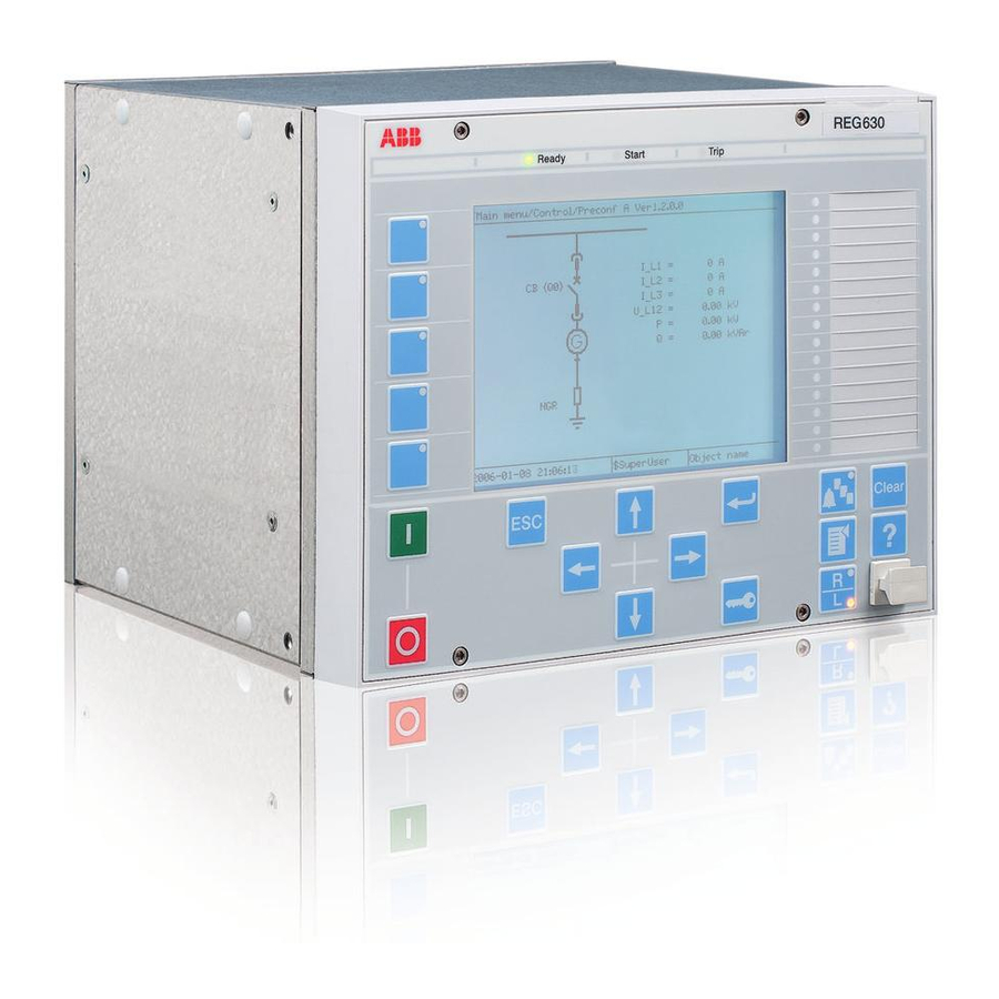
Page 24: Display
Section 3 1MRS756509 E 630 series overview A071260 V3 EN Figure 2: Example of the LHMI 3.2.1 Display The LHMI includes a graphical monochrome display with a resolution of 320 x 240 pixels. The character size can vary. The amount of characters and rows fitting the view depends on the character size and the view that is shown. - Page 25 Section 3 1MRS756509 E 630 series overview A071258 V2 EN Figure 3: Display layout 1 Path 2 Content 3 Status 4 Scroll bar (appears when needed) • The path shows the current location in the menu structure. If the path is too long to be shown, it is truncated from the beginning, and the truncation is indicated with three dots.
- Page 26 Section 3 1MRS756509 E 630 series overview GUID-7586F95B-CC6A-4CA1-A660-DCDB403BE2B6 V1 EN Figure 4: Truncated path The function button panel shows on request what actions are possible with the function buttons. Each function button has a LED indication that can be used as a feedback signal for the function button control action.
-
Page 27: Leds
Section 3 1MRS756509 E 630 series overview GUID-3CBCBC36-EFCE-43A0-9D62-8D88AD6B6287 V1 EN Figure 6: Alarm LED panel The function button and alarm LED panels are not visible at the same time. Each panel is shown by pressing one of the function buttons or the Multipage button. Pressing the ESC button clears the panel from the display. - Page 28 Section 3 1MRS756509 E 630 series overview A071186 V2 EN Figure 7: LHMI keypad with object control, navigation and command push- buttons and RJ-45 communication port 1...5 Function button Close Open Escape Left Down Right Enter Remote/Local Uplink LED Not in use Multipage Menu Clear...
- Page 29 Section 3 1MRS756509 E 630 series overview Object control If the control position of the IED is set to local with the R/L button, the IED can be controlled using the object control buttons. Object to be controlled is selected from the single line diagram. Table 4: Object control push-buttons Name...
-
Page 30: Local Hmi Functionality
Section 3 1MRS756509 E 630 series overview Commands Table 6: Command push-buttons Name Description • Moving directly to Main menu, if Menu currently in any other menu or view. • Moving to the default view, if currently in Main menu. Changing the control position (remote or local) of the device. - Page 31 Section 3 1MRS756509 E 630 series overview Table 8: Ready LED LED state Description Auxiliary supply voltage is disconnected Normal operation Flashing Internal fault has occurred Table 9: Start LED LED state Description Normal operation. A protection function has started and an indication message is displayed. •...
-
Page 32: Parameter Management
Section 3 1MRS756509 E 630 series overview Table 11: Alarm indications LED state Description Normal operation. All activation signals are off. • Follow-S sequence: The activation signal is on. • LatchedColl-S sequence: The activation signal is on, or it is off but the indication has not been acknowledged. -
Page 33: Single-Line Diagram
Section 3 1MRS756509 E 630 series overview GUID-D71BA06D-3769-4ACB-8A32-5D02EA473326 V1 EN Figure 8: RJ-45 communication port and green indicator LED 1 RJ-45 connector 2 Green indicator LED When a computer is connected to the IED front port, the IED's DHCP server for the front interface assigns an IP address to the computer. -
Page 34: Web Hmi
Section 3 1MRS756509 E 630 series overview GUID-FDBBF9B8-39DE-468B-B426-D577A5B63BD0 V1 EN Figure 9: Single-line diagram Web HMI The WHMI enables the user to access the IED via a web browser. The supported Web browser versions are Internet Explorer 8.0, 9.0 and 10.0. WHMI is disabled by default. -
Page 35: Command Buttons
Section 3 1MRS756509 E 630 series overview A071242 V3 EN Figure 10: Example view of the WHMI The WHMI can be accessed locally and remotely. • Locally by connecting the user's computer to the IED via the front communication port. •... -
Page 36: Authorization
Section 3 1MRS756509 E 630 series overview Name Description Triggering the disturbance recorder manually. Saving the disturbance recording. Freezing the values so that updates are not displayed. Receiving continuous updates to the monitoring view. Deleting the disturbance record. Authorization At delivery, logging on to the IED is not required to be able to use the LHMI. The IED user has full access to the IED as a SuperUser until users and passwords are created with PCM600 and written into the IED. - Page 37 Section 3 1MRS756509 E 630 series overview All operational information and controls are available through these protocols. However, some communication functionality, for example, horizontal communication (GOOSE) between the protection relays, is only enabled by the IEC 61850-8-1 communication protocol. Disturbance files are accessed using the IEC 61850 or IEC 60870-5-103 protocols. Disturbance files are also available to any Ethernet based application in the standard COMTRADE format.
-
Page 38: Pcm600 Tool
PCM600 and IED connectivity package version • Protection and Control IED Manager PCM600 Ver. 2.5 or later • ABB REF630 Connectivity Package Ver. 1.3 or later • ABB REG630 Connectivity Package Ver. 1.3 or later • ABB REM630 Connectivity Package Ver. 1.3 or later •... - Page 39 Section 3 1MRS756509 E 630 series overview Download connectivity packages from the ABB Web site http://www.abb.com/substationautomation or directly with Update Manager in PCM600. 630 series Operation Manual...
-
Page 41: Section 4 Using The Hmi
Section 4 1MRS756509 E Using the HMI Section 4 Using the HMI Using the local HMI At delivery, logging on is not required and the user has full access until users and passwords are created with PCM600 and written into the IED. Commands, changing parameter values and resetting indications, for example, are actions requiring password when the password protection is activated. - Page 42 Section 4 1MRS756509 E Using the HMI • Activate the digit to be entered with • Enter the character with Upper and lower case letters are also found by scrolling with the vertical arrows. GUID-A6C9646B-1409-4EDE-8BEC-CD2E7E948A87 V2 EN Figure 12: Entering the password Passwords are case sensitive.
-
Page 43: Logging Off
Section 4 1MRS756509 E Using the HMI 4.1.2 Logging off The user is automatically logged off after the display timeout. The IED returns to a state where only reading is enabled. Manual logoff is also possible. Press To confirm logoff, select Yes and press A071188 V2 EN Figure 15: Logging off... -
Page 44: Identifying The Device
Section 4 1MRS756509 E Using the HMI By default, the control position cannot be local and remote simultaneously. See the technical manual for more information on local and remote control. To control the protection relay, log in with the appropriate user rights. -
Page 45: Adjusting The Display Contrast
Section 4 1MRS756509 E Using the HMI A071192 V4 EN Figure 17: IED information 4.1.6 Adjusting the display contrast Adjust the display contrast anywhere in the menu structure to obtain optimal readability. • To increase the contrast, press simultaneously • To decrease the contrast, press simultaneously To store a selected contrast, change the ContrastLevel parameter via Main menu/Configuration/HMI/LHMI. -
Page 46: Navigating In The Menu
Section 4 1MRS756509 E Using the HMI A071194 V2 EN Figure 18: Changing the LHMI language 4.1.8 Navigating in the menu Navigate the menus and change the display views on the screen with the keypad. • To move to the Main menu or default view, press •... -
Page 47: Scrolling The Display
Section 4 1MRS756509 E Using the HMI 4.1.8.2 Scrolling the display If a menu contains more rows than the display can show at a time, a scroll bar is displayed on the right. A071196 V3 EN Figure 19: Scroll bar on the right •... -
Page 48: Using The Single-Line Diagram
Section 4 1MRS756509 E Using the HMI GUID-A4E4C372-FE36-4CFE-829C-F602CE577E2A V1 EN Figure 20: Function button panel Press the wanted function button. • Press the wanted function button to jump to a certain menu item. The menu opens immediately upon pressing the button. •... -
Page 49: Browsing Setting Values
Section 4 1MRS756509 E Using the HMI GUID-FDBBF9B8-39DE-468B-B426-D577A5B63BD0 V1 EN Figure 21: Example of a single-line diagram Make sure that the R/L button is in local position. Select an object with Selection of an object is indicated with a square border that moves when are used. -
Page 50: Editing Values
Section 4 1MRS756509 E Using the HMI A080004 V2 EN Figure 22: Selecting the setting group number Press to select the setting group number. Press to confirm the setting group selection and to return to the Edit setting group dialog. Press to select Yes and to view the setting group values. -
Page 51: Editing Numerical Values
Section 4 1MRS756509 E Using the HMI Parallel editing is not possible. For example, if a value is edited via WHMI or PCM600, the same value cannot be edited via LHMI at the same time. 4.1.12.1 Editing numerical values Select Main menu/Settings and then a setting. The # character on the right indicates that the parameter belongs to a setting group. -
Page 52: Editing String Values
Section 4 1MRS756509 E Using the HMI For parameters with defined steps, digits smaller than the step value cannot be edited. Press to move the cursor to another digit. To select the minimum or maximum value, select the arrow symbol in front of the value. -
Page 53: Changing The Time Settings In Lhmi
Section 4 1MRS756509 E Using the HMI When editing an enumerated value, the selected value is shown inverted. Press to change the value of an active enumerated value. One press changes the enumerated value by one step in the parameter specific order. -
Page 54: Clearing And Acknowledging
Section 4 1MRS756509 E Using the HMI After changing the parameters marked with !, the IED restarts automatically for the changes to take effect. 4.1.14 Clearing and acknowledging The Clear button is used to reset, acknowledge or clear all messages and indications, including LEDs and latched outputs as well as registers and recordings. -
Page 55: Using The Web Hmi
Section 4 1MRS756509 E Using the HMI Using the Web HMI WHMI is disabled by default. To enable the WHMI, select Main menu/Configuration/HMI/Web HMI/ Operation via the LHMI. To enable writing through the WHMI, select Main menu/ Configuration/HMI/Web HMI/Write mode via the LHMI. To open the WHMI, write the IED IP address to the address bar of the browser. -
Page 56: Logging Out
Section 4 1MRS756509 E Using the HMI 4.2.2 Logging out The user is logged out after a session time-out. GUID-ADAA280F-07CC-41E8-A4C4-8152BA9E7B7E V2 EN Figure 30: Session time-out • To log out manually, click Logout on the menu bar. GUID-3AEE30CE-CB9F-4B9F-8B4A-9C54C4E6A6E6 V3 EN Figure 31: WHMI logout 630 series... -
Page 57: Identifying The Device
Section 4 1MRS756509 E Using the HMI If the WHMI is closed without properly logging out, the WHMI does not reconnect until the set session time-out. 4.2.3 Identifying the device The IED information includes detailed information about the device, for example, revision and serial number. -
Page 58: Menu Structure
Section 4 1MRS756509 E Using the HMI A071242 V3 EN Figure 33: Navigating in the WHMI menus 4.2.4.1 Menu structure The Main menu contains main groups which are divided further into more detailed submenus. • Events • Measurements • Disturbance records •... -
Page 59: Editing Values
Section 4 1MRS756509 E Using the HMI 4.2.6 Editing values Click the menu in the WHMI tree. Click the submenu to see function blocks. Click a function block to see the setting values. Click Enable Write. Some parameters, for example, the IED test mode, cannot be set via the WHMI. - Page 60 Section 4 1MRS756509 E Using the HMI A071246 V2 EN Figure 35: Editing a value • If the entered value is within the accepted value range, the selection is highlighted in green. If the value is out of range, the row is highlighted in red and a warning dialog box is displayed.
-
Page 61: Committing Settings
Section 4 1MRS756509 E Using the HMI If writing is enabled accidentally, click Disable Write. Disable Write cannot be selected, when a value has already been written to the IED. After clicking Write to IED, click either Commit or Reject. 4.2.7 Committing settings Editable values are stored in the non-volatile flash memory. -
Page 62: Clearing And Acknowledging
Section 4 1MRS756509 E Using the HMI A071252 V2 EN Figure 39: Committing changes Committing values takes a few seconds. If the values are not committed, they are not taken into use and they are lost after a reboot. However, in case of changing the time settings in WHMI, the change takes effect immediately without committing the changes. -
Page 63: Selecting The Disturbance Record View
Section 4 1MRS756509 E Using the HMI changes while the user is viewing the latest events. If the user is viewing older events while the event count changes, only the drop-down list is updated. Click Events on the menu bar. Each event view page shows 100 events. -
Page 64: Reading Disturbance Records
Section 4 1MRS756509 E Using the HMI GUID-47BC413D-0794-4ABF-AF6C-6300AF78F375 V1 EN Figure 41: Disturbance record view 4.2.10.1 Reading disturbance records Select Disturbance records/Recordings. Click the icon in the Download column of the record to read a disturbance record. 630 series Operation Manual... -
Page 65: Triggering The Disturbance Recorder Manually
Section 4 1MRS756509 E Using the HMI GUID-4356D2C0-89A4-4953-9F54-40C51331ED7C V1 EN Figure 42: Reading a disturbance record Save the zip file on your computer. Extract the files in the same folder on your computer. Open the disturbance record files with a suitable program. Files are in standard COMTRADE format. -
Page 66: Deleting Disturbance Records
Section 4 1MRS756509 E Using the HMI GUID-D7BDEB43-D302-4017-9B40-C90B5646E558 V1 EN Figure 43: Manual triggering 4.2.10.3 Deleting disturbance records Select Disturbance records/Recordings. Select one or more recordings and click Delete to delete selected records. To delete all records, select Clear disturbances in the Clear menu. 630 series Operation Manual... -
Page 67: Selecting Phasor Diagrams
Section 4 1MRS756509 E Using the HMI GUID-0CC56B38-0E52-4B49-B454-7E92C6873A11 V1 EN Figure 44: Deleting disturbance records Click OK to confirm or Cancel to cancel the deletion. 4.2.11 Selecting phasor diagrams Install or enable the SVG plugin to view the phasor diagrams, if needed. - Page 68 Section 4 1MRS756509 E Using the HMI GUID-DEE30ACE-BCD9-4958-930D-652CEC1B0CAD V1 EN Figure 45: Selecting phasor diagrams Toggle the diagram visibility by selecting the diagram from the drop-down menu. Visible diagrams are indicated with an asterisk *. Change the size of the diagram by changing the zoom value. Click Freeze to stop updating the phasor diagram.
-
Page 69: Section 5 Ied Operation
Section 5 1MRS756509 E IED operation Section 5 IED operation Normal operation In a normal protection relay use situation, the basic operation includes monitoring and checking procedures. • Monitoring measured values • Checking object states • Checking function setting parameters •... -
Page 70: Disturbance Recording Triggering
Section 5 1MRS756509 E IED operation Only authorized and skilled personnel should analyze possible errors and decide on further actions. Otherwise, stored disturbance data can be lost. 5.2.1 Disturbance recording triggering Disturbance recordings are normally triggered by protection relay applications when they detect fault events. -
Page 71: Relay Parametrization
Section 5 1MRS756509 E IED operation The protection relay records relay status data and events. Document all the recorded data from the protection relay before resetting the tripping and relay lockout functions. Relay parametrization Protection relay parameters are set via the LHMI, WHMI or PCM600. Setting parameters need to be calculated according to the electrical network conditions and the electrical characteristics of the protected equipment. -
Page 72: Settings For Different Operating Conditions
Section 5 1MRS756509 E IED operation 5.3.2 Settings for different operating conditions Protection relay settings can be designed for various operation conditions by defining different setting values to different setting groups. The active setting group can be changed by the relay application or manually via the LHMI, WHMI or PCM600. The protection relay contains only one setting group by default. -
Page 73: Section 6 Operating Procedures
Section 6 1MRS756509 E Operating procedures Section 6 Operating procedures Monitoring 6.1.1 Indications The operation of the IED can be monitored via three different indications on the LHMI. • Three indicator LEDs with fixed functionality: Ready, Start and Trip • 15 programmable three-color alarm LEDs which can present 45 virtual LED states •... -
Page 74: Monitoring Alarm Data
Section 6 1MRS756509 E Operating procedures GUID-94D4ED93-44D0-44B3-8861-D9E77FACB83E V2 EN Figure 46: Auto-indication message 6.1.1.2 Monitoring alarm data Active alarms are indicated by the alarm LEDs and the LED in the Multipage button. The alarms are configured with PCM600. The alarm type and information depend on the application configuration. - Page 75 Section 6 1MRS756509 E Operating procedures GUID-1525F611-595F-4952-9900-D60F2C35746E V1 EN Figure 47: Alarm details Press to close the dialog box. Press to close the alarm view. Press to activate the Clear view and to clear alarms. GUID-141FB7EF-052D-44F7-BFF1-5AC766FA4B7A V1 EN Figure 48: Alarm data 630 series Operation Manual...
-
Page 76: Monitoring An Internal Ied Fault
Section 6 1MRS756509 E Operating procedures 6.1.1.3 Monitoring an internal IED fault The flashing green LED indicates an internal IED fault. The fault messages are found in the LHMI menu. Select Main menu/Monitoring/Internal events or Main menu/ Monitoring/IED status to monitor the latest fault indication. Press to scroll the view. -
Page 77: Using The Local Hmi Or Web Hmi For Monitoring
Section 6 1MRS756509 E Operating procedures are also available through the station communication protocols. On LHMI also the fundamental frequency based values (DFT) are available. Invalid or questionable measurement values are presented in parentheses. 6.1.2.1 Using the local HMI or Web HMI for monitoring •... -
Page 78: Creating Disturbance Recordings
Section 6 1MRS756509 E Operating procedures 6.1.3.1 Creating disturbance recordings Normally disturbance recordings are triggered by the IED applications but the recording can also be triggered manually. Set the DRRDRE Operation to “On” via the LHMI or PCM600. At least one channel has to be connected. Select Main menu/Disturbance records. -
Page 79: Controlling And Reading Of Disturbance Recorder Data
Section 6 1MRS756509 E Operating procedures GUID-48497E0F-735B-4259-B80E-29329F8E6C53 V2 EN Figure 51: Monitoring disturbance recorder via the LHMI To view a specific disturbance record, press A list of detail categories is displayed. GUID-CECFCDAB-06F4-4C5E-8244-6E43E89CF47C V2 EN Figure 52: Disturbance record data categories To select a category and view the items under it, press and then 6.1.3.3... -
Page 80: Monitoring Recorded Data
Section 6 1MRS756509 E Operating procedures 6.1.3.4 Monitoring recorded data Some functions, for example, distance protection and fault locator, include data recording functionality. All the information required for later fault analysis is recorded when the function is triggered either internally or externally. One or three sets of recorded data are available saved in data banks 1-3. -
Page 81: Monitoring Events
Section 6 1MRS756509 E Operating procedures 6.1.3.5 Monitoring events The event view contains a list of events produced by the application configuration. The events are grouped by day, and each event takes one line. Select the order of events with the setting Main menu/Configuration/HMI/LHMI/EvListSrtOrder. Select Main menu/Events. -
Page 82: Controlling
Section 6 1MRS756509 E Operating procedures For more information, see the PCM600 documentation. Controlling 6.2.1 Controlling circuit breakers and disconnectors Before the control via LHMI is possible, the R/L button has to be in local position. The primary equipment can be controlled via the LHMI with the Open and Close buttons when the IED is set to local control mode and the user is authorized to access control operations. -
Page 83: Resetting The Ied
Section 6 1MRS756509 E Operating procedures GUID-CD28265F-7984-46A8-98F3-6866C3F7AAF6 V1 EN Figure 56: Closing a circuit breaker • Press to cancel the operation. Press to move between single-line diagram pages. The time between selecting the object and giving a control command is restricted by an adjustable timeout. When an object is selected, the control command has to be given within this time. -
Page 84: Changing The Ied Functionality
Section 6 1MRS756509 E Operating procedures A071214 V3 EN Figure 57: Clear view The content of the Clear menu depends on the pre-configuration or on the functions configured with PCM600. Select the item to be cleared with Press , select OK to confirm the selection or Cancel to cancel the selection. To clear other items, repeat the steps. - Page 85 Section 6 1MRS756509 E Operating procedures Select Main menu/Settings/Activate setting group/ActiveSetGrp and press GUID-3715ABC3-DC1B-42DC-AEBE-443CBB380474 V2 EN Figure 58: Active setting group Select the setting group with Press to confirm the selection or to cancel. GUID-CA252C71-1C52-4C77-9F82-47B2BC585939 V2 EN Figure 59: Selecting the active setting group Commit the settings.
-
Page 86: Browsing And Editing Setting Group Values
Section 6 1MRS756509 E Operating procedures 6.4.1.2 Browsing and editing setting group values Select Main menu/Settings/Settings and press Setting group 1 is the default setting group to be edited. GUID-05678769-CBFB-415D-B877-D49DB3629540 V2 EN Figure 60: Selecting a setting group for editing Press on the Setting group line in the dialog box to activate selection mode. - Page 87 Section 6 1MRS756509 E Operating procedures GUID-A5D7D19E-B5D9-4BA1-B895-273AA84ACC2D V1 EN Figure 62: Selecting the function category To browse the function blocks, scroll the list with Function blocks available depend on the application configuration. To move back to the list, press To select a function block, press GUID-F6ECE14F-59A5-4BE6-B716-CAC4BB715189 V1 EN Figure 63: Function block settings...
-
Page 88: Activating Leds
Section 6 1MRS756509 E Operating procedures value in the selected setting group. The active setting group is marked with an asterisk *. GUID-8BE02088-C813-4F92-9B75-C7DFF99F5002 V1 EN Figure 64: Changing the setting value Press to change the value. 10. Confirm the change with 6.4.2 Activating LEDs To activate the LEDs, they must be configured with PCM600. - Page 89 Section 6 1MRS756509 E Operating procedures The list can contain three alarm groups at the maximum. The amount of groups depends on the amount of LEDs taken into use. Select an alarm group with and press Select an Alarm LED with Press to confirm the selection and to change the Alarm LED mode.
-
Page 91: Section 7 Troubleshooting
Inspect the IED visually. • Inspect the IED visually to find any physical error causes. • If you can find some obvious physical damage, contact ABB for repair or replacement actions. Check whether the error is external or internal. •... -
Page 92: Checking The Communication Link Operation
Section 7 1MRS756509 E Troubleshooting 7.1.3.1 Checking the communication link operation There are several different communication links on the product. First check that all communication ports that are used for communication are turned on. To check that optical serial port hardware is working, check the optical fibres for light. -
Page 93: Running The Display Test
LHMI in Main menu/ Monitoring/IED status. The ABB logo together with the IED FAILURE message appear on the screen after a five minutes' communication break between the LHMI and the IED. The LHMI panel displays the message due to a communication failure or a severe functional error in the IED. -
Page 94: Warnings
Section 7 1MRS756509 E Troubleshooting Table 15: Internal fault indications Fault indication Additional information Internal Fault Hardware error with the real time clock. Real Time Clock Error Internal Fault One or more of the application threads Runtime Exec. Error are not working properly. Internal Fault This signal will be activated when the SW Watchdog Error... -
Page 95: Correction Procedures
Section 7 1MRS756509 E Troubleshooting The messages are listed in the LHMI menu under the event list. The signal status data is found under the IED status and in the internal event list. Table 17: Additional indications Warning indication Additional information Time Synch Error Source of the time synchronization is lost or time system has made a time reset. -
Page 96: Inspecting The Wiring
Section 7 1MRS756509 E Troubleshooting 7.3.3.1 Inspecting the wiring The physical inspection of wiring connections often reveals the wrong connection for phase currents or voltages. Even when the phase current or voltage connections to IED terminals are correct, wrong polarity of one or more measurement transformers can cause problems. - Page 97 Section 7 1MRS756509 E Troubleshooting GUID-BBAEAF55-8D01-4711-A71D-BBC76B60BA3D V1 EN Figure 66: Testing output contacts using the voltage drop method 1 Contact current 2 Contact voltage drop 3 Load 4 Supply voltage 630 series Operation Manual...
- Page 98 Section 7 1MRS756509 E Troubleshooting GUID-31DF5495-91F1-4A4B-8FD5-50625038961E V1 EN Figure 67: Testing a trip contact 1 Trip contact under test 2 Current limiting resistor • To check the status of the output circuits driving the output relay via the LHMI, select Main menu/Monitoring/I/O status/Binary output modules and then navigate to the board with the actual binary output to be checked.
-
Page 99: Inspecting The Rtd Wiring
Section 7 1MRS756509 E Troubleshooting The second signal is the status Normal or Forced. Forced status is only achieved when the BO is set to “Forced” or operated on the LHMI. Set the parameter TestMode to “Off” after completing these tests. - Page 100 Section 7 1MRS756509 E Troubleshooting PT 100 PT 250 NI 100 NI 120 CU 10 °C °C °C °C °C -50.8 151.8 -30.6 176.3 -10.2 199.3 151.8 20.5 182.2 51.6 82.9 114.6 146.5 189.6 RTD connector numbering is an example of a 4U case. See the technical manual for complete terminal diagrams.
- Page 101 Section 7 1MRS756509 E Troubleshooting GUID-A1C53A59-D607-4E0D-B3BF-7E12BEA35E9A V1 EN Figure 69: Testing voltage input by connecting voltage source directly to connector and measuring input voltage by multimeter GUID-DC08299A-C531-4C02-9273-AA9BD6ED7F6E V1 EN Figure 70: Testing current input by connecting voltage source directly to connector and measuring input current by multimeter Current type measurement mode can be verified by connecting a voltage source on the input, for example, 1 V DC.
- Page 102 Section 7 1MRS756509 E Troubleshooting GUID-E486DBB7-EB19-436C-9294-90B8B5FF398D V1 EN Figure 71: Testing mA output by connecting multimeter directly to connector and measuring output current by multimeter • Check the status of the output circuits driving the mA outputs via the LHMI. Select Main menu/Monitoring/I/O status/mA output modules/RTD3 and check the output status and value for the channel under inspection.
- Page 103 Section 7 1MRS756509 E Troubleshooting Set the parameter TestMode to”Off” after completing the tests. The Start LED stops flashing when the relay is no longer in test mode. 630 series Operation Manual...
-
Page 105: Section 8 Glossary
Section 8 1MRS756509 E Glossary Section 8 Glossary 100BASE-FX A physical medium defined in the IEEE 802.3 Ethernet standard for local area networks (LANs) that uses fiber optic cabling COMTRADE Common format for transient data exchange for power systems. Defined by the IEEE Standard. Connectivity A collection of software and information related to a package... - Page 106 Section 8 1MRS756509 E Glossary 1. Internal fault 2. Internal relay fault Local area network Connector type for glass fiber cable, IEC 61754-20 Liquid crystal polymer Light-emitting diode LHMI Local human-machine interface 1. Personal computer 2. Polycarbonate PCM600 Protection and Control IED Manager Remote/Local REF630 Feeder protection and control relay...
- Page 108 — ABB Distribution Solutions Distribution Automation P.O. Box 699 FI-65101 VAASA, Finland Phone +358 10 22 11 www.abb.com/mediumvoltage www.abb.com/relion © Copyright 2019 ABB. All rights reserved.