Table of Contents
Quick Links
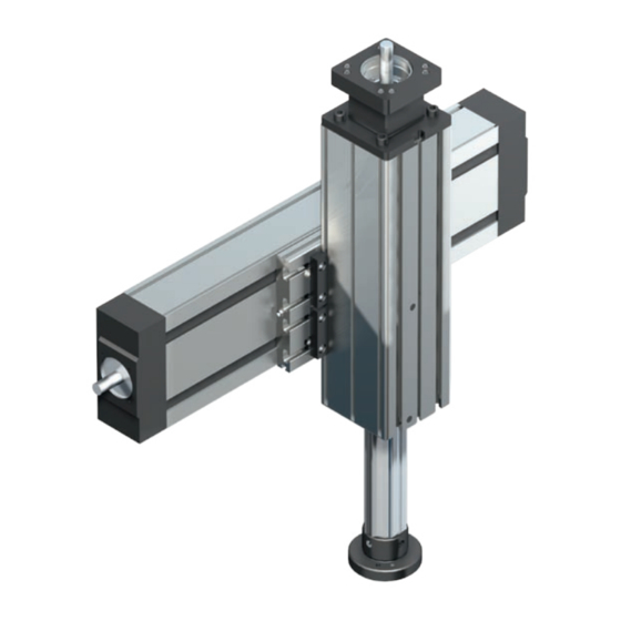
Vorschubmodule VKK
Anleitung für
Feed Modules VKK
Instructions for
modules de déplacement VKK
Instructions pour
attuatori lineari VKK
Istruzioni per
The Drive & Control Company
R320103150 (2009.09)
DE+EN+FR+IT
Montage
Inbetriebnahme
Mounting
Start-up
Montage
Mise en service
Montaggio
Messa in funzione
Wartung
Maintenance
Entretien
Manutenzione
Table of Contents

Related Manuals for Bosch Rexroth VKK Series


Summary of Contents for Bosch Rexroth VKK Series
- Page 1 Vorschubmodule VKK R320103150 (2009.09) Anleitung für DE+EN+FR+IT Feed Modules VKK Instructions for modules de déplacement VKK Instructions pour attuatori lineari VKK Istruzioni per The Drive & Control Company Montage Inbetriebnahme Wartung Mounting Start-up Maintenance Montage Mise en service Entretien Montaggio Messa in funzione Manutenzione...
- Page 2 Bosch Rexroth AG Anleitung für VKK R320103150 (2009.09) • DE+EN+FR+IT Allgemeine Hinweise General Notes Zu dieser Anleitung About these Instructions 1.2 Sicherheitshinweise 1.2 Safety Notes Übersicht Vorschub module VKK Overview, Feed Modules VKK 2.1 Typenübersicht 2.1 Type Designations 2.2 Baugruppen 2.2 Assemblies...
-
Page 3: Entretien
R320103150 (2009.09) • DE+EN+FR+IT Instructions for VKK Bosch Rexroth AG Indications générales Informazioni generali Concernant les présentes instructions Riguardanti le presenti istruzioni 1.2 Instructions de sécurité 1.2 Avvertenze per la sicurezza Aperçu des modules de déplacement VKK 9 Prospetto degli attuatori lineari VKK 2.1 Aperçu des types... -
Page 4: Allgemeine Hinweise
Bosch Rexroth AG Anleitung für VKK R320103150 (2009.09) • DE+EN+FR+IT Allgemeine Hinweise General Notes Zu dieser Anleitung About these Instructions Als Sicherheitshinweise werden folgende Piktogramme ver- The following symbols are used to identify safety notes: wendet: GEFAHR! DANGER! Lebensgefahr beim Berühren span- Danger to life upon contact with live nungsführender Teile! Gerät spannungs-... -
Page 5: Indications Générales
R320103150 (2009.09) • DE+EN+FR+IT Instructions for VKK Bosch Rexroth AG Indications générales Informazioni generali Concernant les présentes instructions Riguardanti le presenti istruzioni Les pictogrammes suivants sont utilisés en tant que symboles Sono utilizzati i seguenti simboli grafici quali avvertenze per la de sécurité... - Page 6 Bosch Rexroth AG Anleitung für VKK R320103150 (2009.09) • DE+EN+FR+IT 1.2 Sicherheitshinweise WARNUNG! Nicht bestimmungsgemäßer Gebrauch des Vorschubmoduls kann zu Unfäl- len mit Personen- und Sachschäden sowie zu Produktionsausfällen führen! • Bei der Gestaltung der Anschluss- konstruktion alle einschlägigen Sicherheitsvorschriften beachten, z. B.
-
Page 7: Safety Notes
R320103150 (2009.09) • DE+EN+FR+IT Instructions for VKK Bosch Rexroth AG 1.2 Safety Notes 1.2 Instructions de sécurité 1.2 Avvertenze per la sicurezza WARNING! AVERTISSEMENT ! AVVERTIMENTO! Improper use of the Feed Module Tout application non prévue du mo- L’impiego non conforme alla desti- may result in accidents with injury dule de déplacement peut provoquer... - Page 8 Bosch Rexroth AG Anleitung für VKK R320103150 (2009.09) • DE+EN+FR+IT Übersicht Vorschub module VKK 15-50 2.1 Typenübersicht Rexroth Vorschubmodule VKK sind in drei Baugrößen erhältlich. Sie werden auf Wunsch einbaufertig vormontiert geliefert. Genaue Daten und Maße siehe VKK 15-70 Katalog.
- Page 9 R320103150 (2009.09) • DE+EN+FR+IT Instructions for VKK Bosch Rexroth AG Overview, Aperçu des modules Prospetto degli attuatori Feed Modules VKK de déplacement VKK lineari VKK 2.1 Type Designations 2.1 Aperçu des types 2.1 Tipologia Rexroth Feed Modules VKK are available Les modules de déplacement VKK...
- Page 10 Bosch Rexroth AG Anleitung für VKK R320103150 (2009.09) • DE+EN+FR+IT Befestigung Vorschub- modul 3.1 Einbausituation Das Vorschubmodul wird am Haupt- körper mit der Anschlusskonstruktion verbunden. Die Befestigungsfläche (1) liegt gegenüber der Profilnut (3) für das Schaltsystem. Für die Aufnahme von Zentrierringen sind werkseitig über die...
-
Page 11: Mounting Accessories
R320103150 (2009.09) • DE+EN+FR+IT Instructions for VKK Bosch Rexroth AG Mounting the Fixation du module Fissaggio degli attuatori Feed Module de déplacement lineari 3.1 Mounting Situation 3.1 Situation du montage 3.1 Condizioni di funzionamento The Feed Module is mounted to the Le module de déplacement est relié... - Page 12 Bosch Rexroth AG Anleitung für VKK R320103150 (2009.09) • DE+EN+FR+IT Spannstücke VKK 15-50 VKK 15-70, VKK 25-100 Das Vorschubmodul wird mit Spann- stücken an die Anschlusskonstruktion montiert. ± 0,1 ± 0,1 (mm) (mm) VKK 15-50 62,5 75,5 VKK 15-70 86,0...
- Page 13 R320103150 (2009.09) • DE+EN+FR+IT Instructions for VKK Bosch Rexroth AG Clamping fixtures Pièces de bridage Staffe The Feed Module is mounted to the ad- La fixation du module de déplacement L’attuatore lineare viene montato con joining structure by means of clamping sur la construction périphérique s’effec-...
- Page 14 Bosch Rexroth AG Anleitung für VKK R320103150 (2009.09) • DE+EN+FR+IT 3.3 Befestigung an vorhandenen Vorschubmodul VKK an Compactmodul CKK Modulen Feed Module VKK mounted to Compact Module CKK Das Vorschubmodul VKK kann ohne Module de déplacement VKK sur module compact CKK...
- Page 15 R320103150 (2009.09) • DE+EN+FR+IT Instructions for VKK Bosch Rexroth AG 3.3 Mounting to Installed 3.3 Fixation sur modules 3.3 Fissaggio sui Linearmoduli Modules existants esistenti The Feed Module VKK can be directly Le module de déplacement VKK peut Gli attuatori lineari VKK possono essere mounted (without any intermediate plate) être fixé...
- Page 16 Bosch Rexroth AG Anleitung für VKK R320103150 (2009.09) • DE+EN+FR+IT 3.4 Befestigung von Anbauteilen über Nutensteine und Federn Gegenüber der Montagefläche können Anbauteile über Nutensteine und Federn in den beiden T-Nuten (1) befestigt werden (nicht bei VKK 15-50). Dabei die maximal zulässigen Anziehdre- momente nicht überschreiten ! ...
- Page 17 R320103150 (2009.09) • DE+EN+FR+IT Instructions for VKK Bosch Rexroth AG 3.4 Mounting of Attachments 3.4 Fixation d’éléments à monter 3.4 Fissaggio di accessori using Sliding Blocks and par réglettes de rainure et con inserti filettati Springs ressorts e molle On the side opposite the mounting Des éléments à...
- Page 18 Bosch Rexroth AG Anleitung für VKK R320103150 (2009.09) • DE+EN+FR+IT Übersicht Anbauteile 4.1 Schaltsystem und Antrieb Auf Wunsch wird das Vorschubmodul VKK mit den folgenden Komponenten geliefert. Schaltsystem mit zwei Magnetfeld- sensoren ! 5 Schalternut (mittlere Profilnut) Schalter (Magnetfeldsensor) Kabel Der Schaltgeber ist ein Magnet, der in der Pinole integriert ist.
- Page 19 R320103150 (2009.09) • DE+EN+FR+IT Instructions for VKK Bosch Rexroth AG Overview, Aperçu des éléments Assemblaggio degli Attachments à monter accessori 4.1 Switching System and 4.1 Système de commutation 4.1 Sistema interruttori Drive Unit et entraînement e azionamento If required, the Feed Module VKK can Sur demande, le module de déplacement...
- Page 20 Bosch Rexroth AG Anleitung für VKK R320103150 (2009.09) • DE+EN+FR+IT Montage Schaltsystem 5.1 Hinweise GEFAHR! Stromversorgung unterbrechen! Voraussetzung für den Einbau des Schaltsystems ist die Befestigung des Vorschubmodul-Hauptkörpers. Das Vorschubmodul ist auf einer Seite mit einer Profilnut für Magnetfeldsensor (1) und Kabelführung (2) versehen. Der Schalteranbau ist nur auf dieser Seite möglich.
- Page 21 R320103150 (2009.09) • DE+EN+FR+IT Instructions for VKK Bosch Rexroth AG Mounting the Switching Montage du système Montaggio del sistema System de commutation interruttori 5.1 Notes 5.1 Remarques 5.1 Avvertenze DANGER! DANGER ! PERICOLO! Switch off the power supply! Couper l’alimentation électrique !
-
Page 22: Technische Daten
Bosch Rexroth AG Anleitung für VKK R320103150 (2009.09) • DE+EN+FR+IT 5.3 Technische Daten Für Magnetfeldsensoren ohne und mit Stecker. Hall-Sensor Reed-Sensor Kontaktart PNP-Öffner Kontaktart Wechsler Betriebsspannung 3,8–30 V DC Schaltspannung max. 100 V DC Stromaufnahme max. 10 mA Schaltstrom max. 0,5 mA Ausgangsstrom max. -
Page 23: Technical Data
R320103150 (2009.09) • DE+EN+FR+IT Instructions for VKK Bosch Rexroth AG 5.3 Technical data Caractéristiques techniques Dados Técnicos For magnetic field sensors with and with- Pour capteurs de champ magnétique Per sensori magnetici senza e con spina. out connector. avec ou sans fiche. - Page 24 Bosch Rexroth AG Anleitung für VKK R320103150 (2009.09) • DE+EN+FR+IT 5.4 Magnetfeldsensor einbauen VKK 15-50 • Sensor (1) mit Gewindestift (2) nach außen in die mittlere Profilnut des Gehäuses einführen. • Schaltpunkt einstellen und Sensor mit Gewindestift (2) fixieren. •...
- Page 25 R320103150 (2009.09) • DE+EN+FR+IT Instructions for VKK Bosch Rexroth AG 5.4 Installing the Magnetic Field 5.4 Montage du capteur de 5.4 Montare il sensore Sensor champ magnétique magnetico • Insert the sensor (1) with the set screw • Introduire le capteur (1) dans la rainure •...
- Page 26 Bosch Rexroth AG Anleitung für VKK R320103150 (2009.09) • DE+EN+FR+IT Montage Antrieb 6.1 Hinweise (Nm) Maximales Drehmoment und maximale Drehzahl des Motors dürfen die Grenzwerte des Vorschubmoduls nicht überschreiten! Siehe Katalog. 6.2 Motor mit Kupplung montieren Kupplung montieren • Kupplung (2) auf Antriebszapfen ste- cken.
- Page 27 R320103150 (2009.09) • DE+EN+FR+IT Instructions for VKK Bosch Rexroth AG Mounting the Drive Unit Montage de l’entraînement Montaggio del motore 6.1 Notes 6.1 Remarques 6.1 Avvertenze The maximum torque and maxi- Le couple de rotation maximal La coppia massima ed il regime...
- Page 28 Bosch Rexroth AG Anleitung für VKK R320103150 (2009.09) • DE+EN+FR+IT 6.3 Motor mit Kupplung demontieren GEFAHR! Lebensgefahr beim Berühren span- nungsführender Teile! Gerät span- nungsfrei machen! Spannungsfreiheit prüfen! Stromversorgung gegen unbeabsichtigtes oder unbefugtes Wiedereinschalten sichern! Erden und kurzschließen! Spannungsführende Anlagenteile abdecken oder abschran- ken! •...
- Page 29 R320103150 (2009.09) • DE+EN+FR+IT Instructions for VKK Bosch Rexroth AG 6.3 Removing the Motor with 6.3 Démontage du moteur avec 6.3 Smontare il motore con il Coupling accouplement giunto DANGER! DANGER ! PERICOLO! Danger to life upon contact with live...
- Page 30 Bosch Rexroth AG Anleitung für VKK R320103150 (2009.09) • DE+EN+FR+IT 6.4 Motor mit Riemenvor gelege montieren Schutzprofil montieren • Schutzprofil (1) des Riemenvorgeleges an Traverse festschrauben (Anzieh- drehmoment M (Nm) 6.4.1 Spindelseitiges Riemenrad montieren • Spannsatz (1) leicht einölen. Kein Öl mit MoS -Zusätzen...
- Page 31 R320103150 (2009.09) • DE+EN+FR+IT Instructions for VKK Bosch Rexroth AG 6.4 Mounting the Motor with 6.4 Montage du moteur avec 6.4 Montare il motore con la Timing Belt Side Drive renvoi par poulie et courroie trasmissione a cinghia e puleggia Montage du profilé...
- Page 32 Bosch Rexroth AG Anleitung für VKK R320103150 (2009.09) • DE+EN+FR+IT Gegenlager montieren (nur VKK 15-50) • Ersten Sicherungsring (3) auf Spin- delende als Anschlag aufschieben. • Lager (2) per Hand auf Spindelende aufschieben und mit zweitem Siche- rungsring (1) sichern.
- Page 33 R320103150 (2009.09) • DE+EN+FR+IT Instructions for VKK Bosch Rexroth AG Mounting the counterbearing Montage du contre-palier Montare il controsupporto (only for VKK 15-50) (uniuement pour le VKK 15-50) (solo VKK 15-50) • Push the first lock washer (3) onto the •...
- Page 34 Bosch Rexroth AG Anleitung für VKK R320103150 (2009.09) • DE+EN+FR+IT Riemen spannen: • Motorbefestigung lockern. • Eine geeignete Traverse (4) an die beiden Motorleisten (3) schrauben. • Traverse (4) mit Vorspannkraft F vom (kg) (kg) Schutzprofil wegziehen und Befesti- gungsschrauben festziehen.
- Page 35 R320103150 (2009.09) • DE+EN+FR+IT Instructions for VKK Bosch Rexroth AG Tensioning the belt: Précharge de la courroie: Tendere la cinghia: • Loosen the motor mounting screws. • Desserrer les vis de fixation du moteur. • Allentare il fissaggio del motore.
- Page 36 Bosch Rexroth AG Anleitung für VKK R320103150 (2009.09) • DE+EN+FR+IT 6.5 Motor mit Riemenvorgelege demontieren GEFAHR! Lebensgefahr beim Berühren span- nungsführender Teile! Gerät span- nungsfrei machen! Spannungsfreiheit prüfen! Stromversorgung gegen unbeabsichtigtes oder unbefugtes Wiedereinschalten sichern! Erden und kurzschließen! Spannungsführende Anlagenteile abdecken oder abschran-...
- Page 37 R320103150 (2009.09) • DE+EN+FR+IT Instructions for VKK Bosch Rexroth AG 6.5 Removing the Motor with 6.5 Démontage du moteur avec 6.5 Smontare il motore con la Timing Belt Side Drive renvoi par poulie et courroie trasmissione a cinghia e puleggia...
- Page 38 Bosch Rexroth AG Anleitung für VKK R320103150 (2009.09) • DE+EN+FR+IT Montage Anbauelemente Ø12 Standardflansch Gewindestift ISO 4026 – M10 x 12 Zentrierbohrungen für Zentrierringe 1,6 mm tief Zentrierbohrungen für Zentrierringe 2,1 mm tief 7.1.1 Montage Standardflansch • Standardflansch auf den Aufnahme- u (Nm) zapfen schieben.
- Page 39 R320103150 (2009.09) • DE+EN+FR+IT Instructions for VKK Bosch Rexroth AG Mounting the Montage des Montaggio di Connection Elements éléments à monter elementi Standard Flange Bride standard Flangia standard Set screw ISO 4026 – M10 x 12 Vis sans tête ISO 4026 – M10 x 12 Grano filettato ISO 4026 –...
- Page 40 Bosch Rexroth AG Anleitung für VKK R320103150 (2009.09) • DE+EN+FR+IT Adapter für GSP Greifer GSP Befestigungsschrauben Verbindungsplatte (Adapter für GSP) Befestigungsschrauben Zentrierringe Standardflansch Gewindestifte • Greifer (1) mit zwei Schrauben (4) an die Verbindungsplatte (3) festschrau- ben. • Zentrierringe (5) einlegen und Verbin- dungsplatte an Standardflansch (6) schrauben.
- Page 41 R320103150 (2009.09) • DE+EN+FR+IT Instructions for VKK Bosch Rexroth AG Adaptor for GSP Plaque d’adaptation pour GSP Adattatore per GSP Gripper GSP Préhenseur GSP Pinza GSP Mounting screws Vis de fixation Viti di fissaggio Connection plate (adaptor for GSP) Plaque de liaison (plaque d’adaptation Piastra d’accoppiamento (adattatore...
-
Page 42: Elektrische Anschlüsse
Bosch Rexroth AG Anleitung für VKK R320103150 (2009.09) • DE+EN+FR+IT Inbetriebnahme 8.1 Elektrische Anschlüsse GEFAHR! Sicherheitsvorschriften für Arbeiten an elektrischen Anlagen beachten! An- schluss der DC-Versorgung nur durch qualifizierte Elektro-Fachkraft. Leistungskabel und Signallei- tungen räumlich getrennt verlegen! • Regeln zur elektromagnetischen Ver- träglichkeit beachten. -
Page 43: Electrical Connections
R320103150 (2009.09) • DE+EN+FR+IT Instructions for VKK Bosch Rexroth AG Start-up Mise en service Messa in funzione 8.1 Electrical Connections 8.1 Raccordements électriques 8.1 Collegamenti elettrici DANGER! DANGER ! PERICOLO! Follow the safety regulations for wor- Respecter les prescriptions relatives... - Page 44 Bosch Rexroth AG Anleitung für VKK R320103150 (2009.09) • DE+EN+FR+IT Wartung 9.1 Schmierung Wartungspunkte Die Wartung beschränkt sich auf das Schmieren des Kugelgewindetriebes und der Führungswagen mit einer handels- üblichen Handpresse. Die Grundschmie- rung geschieht beim Hersteller. VKK 15-50 Düsenrohre mit passendem Mund- stück können unter der Bestellnummer...
- Page 45 R320103150 (2009.09) • DE+EN+FR+IT Instructions for VKK Bosch Rexroth AG Maintenance Entretien Manutenzione 9.1 Lubrication 9.1 Lubrification 9.1 Lubrificazione Maintenance points Points de lubrification (d’entretien) Punti di manutenzione The only maintenance required is lubrica- L’entretien se limite à une relubrification La manutenzione è...
-
Page 46: Austausch Baugruppen
Der kundenseitige Ausbau der nicht be- schriebenen Baugruppen oder Bauteilen ist nicht zulässig. Diese Baugruppen oder Bauteile können nur vom Kunden- dienst der Bosch Rexroth AG fachge- recht ausgetauscht werden. Senden Sie das komplette Vorschubmodul ohne Anbauteile an die Bosch Rexroth AG. - Page 47 éléments ou ensembles non décrits. del Cliente dei gruppi di componenti o Ces éléments ou ensembles ne peu- only be replaced by Bosch Rexroth AG dei singoli componenti che non sono stati after sales specialists. Dismantling by the vent être remplacés selon la technique descritti.
- Page 48 97424 Schweinfurt, Germany Telefon +49 9721 937-0 Telefax +49 9721 937-275 Internet www.boschrexroth.com/dcl Technische Änderungen vorbehalten. Subject to technical modifications. Sous réserve de modifications techniques. Soggetto a modifiche tecniche. © Bosch Rexroth AG 2009 Printed in Germany R320103150 (2009.09) DE+EN+FR+IT • DCL/MKT2...