
Related Manuals for Bosch Rextroth Indramat RECO R-IB IL CNT


Summary of Contents for Bosch Rextroth Indramat RECO R-IB IL CNT
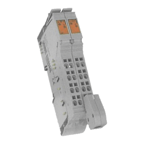
- Page 1 RECO Inline Counter Terminal R-IB IL CNT Application Manual SYSTEM200 DOK-CONTRL-R-IL*CNT***-AW02-EN-P...
- Page 2 About this Documentation Counter Terminal RECO Inline Title Counter Terminal R-IB IL CNT Application Manual Type of Documentation DOK-CONTRL-R-IL*CNT***-AW02-EN-P Document Typecode Document Number, 120-0400-B344-02/EN Internal File Reference This documentation Purpose of Documentation • describes the commissioning and programming of the module within a Reco Inline station, •...
-
Page 3: Table Of Contents
Counter Terminal Contents Contents Functional Description of the Terminal Functional Description........................1-1 Features of the Terminal......................1-1 Areas of Usage ........................1-2 Design of the Terminal ........................1-3 Housing Dimensions ........................ 1-3 Assignment of Terminal Points ....................1-5 Diagnostic and Status Indicators ..................... 1-6 Internal Block Diagram...................... - Page 4 Contents Counter Terminal Connecting Sensors and Actuators ....................4-2 Connection Methods for Sensors and Actuators ..............4-2 Connecting a 24 V Sensor ....................... 4-3 Connecting a 5 V Sensor ......................4-4 Connecting an Actuator ......................4-5 Connecting Lines ........................... 4-6 Connecting Unshielded Lines ....................
- Page 5 Counter Terminal Contents Glossary 10 List of Figures 10-1 11 Index 11-1 12 Service & Support 12-1 12.1 Helpdesk ............................12-1 12.2 Service-Hotline..........................12-1 12.3 Internet ............................12-1 12.4 Vor der Kontaktaufnahme... - Before contacting us..............12-1 12.5 Kundenbetreuungsstellen - Sales & Service Facilities ..............12-2 DOK-CONTRL-R-IL*CNT***-AW02-EN-P...
- Page 6 Contents Counter Terminal DOK-CONTRL-R-IL*CNT***-AW02-EN-P...
-
Page 7: Functional Description Of The Terminal
Counter Terminal Functional Description of the Terminal Functional Description of the Terminal Functional Description The R-IB IL CNT terminal is a counter terminal designed for use within an inline station. The counter terminal is also simply called a counter. The counter detects and processes fast pulse sequences of sensors. It has a counter input (source), a control input (gate) and a freely configurable switch output that is set independently by the module. -
Page 8: Areas Of Usage
Functional Description of the Terminal Counter Terminal • Pulse generator: The pulse generator generates square signals with frequencies of 1 kHz to 10 kHz in 500 Hz steps. • The event count and frequency measurement modes deliver a 24 bit test value;... -
Page 9: Design Of The Terminal
Counter Terminal Functional Description of the Terminal Frequency measurement is suitable for measuring speeds. Frequency measurement You can use the time measurement option for a most varied range of Time measurement applications. • One example would be to determine the size of a part using the time measurement. -
Page 10: Fig. 1-3: Dimensions Of The Electronics Base Of The R-Ib Il Cnt Terminal
Functional Description of the Terminal Counter Terminal Electronic socket 7 1 , 5 m m ( 2 . 8 1 5 " ) 2 4 , 4 m m 5 5 2 0 1 0 2 2 ( 0 . 9 6 1 " ) 55201022.eps Fig. -
Page 11: Assignment Of Terminal Points
Counter Terminal Functional Description of the Terminal Assignment of Terminal Points The R-IB IL AO/CNT-PLSET connector set has been designed for connecting the lines. It comprises one R-IB IL SCN-6 SHIELD shielded connector and one R-IB IL SCN-8 standard connector. You must use the shielded connector when you use shielded lines. -
Page 12: Diagnostic And Status Indicators
Functional Description of the Terminal Counter Terminal Connector Terminal Signal Assignment point Counter input 24 V (source) Control input 24 V (gate) Sensor voltage +24 V Sensor voltage +24 V Ground for the counter input (source) and the segment voltage Ground for the control input (gate) and the sensor voltage Shield... - Page 13 Counter Terminal Functional Description of the Terminal The display of the counter terminal informs you of the following Diagnostics conditions: LED green Diagnostics Local bus is active Flashing: Logic voltage available, local bus not active 0.5 Hz: (at a slow rate) 2 Hz: Logic voltage available, LOCAL BUS active, peripheral fault...
-
Page 14: Internal Block Diagram
Functional Description of the Terminal Counter Terminal Internal Block Diagram I N T E R B U S O P C A N A µ P & M U X ≥ 1 + 2 4 V ( U I N I + 2 4 V ( U 5 9 7 9 0 0 0 4 59790004.eps... - Page 15 Counter Terminal Functional Description of the Terminal Digital output Transistor (output driver) Coupling interface Component with multiplexer, filter and logic µ P Sensor supply voltage with short-circuit protection Ground Functional earth ground Terminal connection Voltage or data jumpers with lateral routing contacts DOK-CONTRL-R-IL*CNT***-AW02-EN-P...
- Page 16 1-10 Functional Description of the Terminal Counter Terminal DOK-CONTRL-R-IL*CNT***-AW02-EN-P...
-
Page 17: Important Directions For Use
Counter Terminal Important Directions for use Important Directions for use Appropriate Use Introduction Rexroth Indramat products represent state-of-the-art developments and manufacturing. They are tested prior to delivery to ensure operating safety and reliability. The products may only be used in the manner that is defined as appropriate. -
Page 18: Areas Of Use And Application
Important Directions for use Counter Terminal Areas of Use and Application The RECO Inline system is a decentralized modular fieldbus-coupled input and output system. The RECO Inline system by Rexroth Indramat is intended for the cases of use listed below. •... -
Page 19: Safety Instructions For Electric Drives And Controls
Counter Terminal Safety Instructions for Electric Drives and Controls Safety Instructions for Electric Drives and Controls Introduction Read these instructions before the initial startup of the equipment in order to eliminate the risk of bodily harm or material damage. Follow these safety instructions at all times. -
Page 20: Hazards By Improper Use
Safety Instructions for Electric Drives and Controls Counter Terminal Hazards by Improper Use High voltage and high discharge current! Danger to life or severe bodily harm by electric shock! DANGER Dangerous movements! Danger to life, severe bodily harm or material damage by unintentional motor movements! DANGER High electrical voltage due to wrong... -
Page 21: General Information
Counter Terminal Safety Instructions for Electric Drives and Controls General Information • Rexroth Indramat GmbH is not liable for damages resulting from failure to observe the warnings provided in this documentation. • Read the operating, maintenance and safety instructions in your language before starting up the machine. - Page 22 Safety Instructions for Electric Drives and Controls Counter Terminal • Operation is only permitted if the national EMC regulations for the application are met. The instructions for installation in accordance with EMC requirements can be found in the documentation "EMC in Drive and Control Systems".
-
Page 23: Protection Against Contact With Electrical Parts
Counter Terminal Safety Instructions for Electric Drives and Controls Protection Against Contact with Electrical Parts Note: This section refers to equipment and drive components with voltages above 50 Volts. Touching live parts with voltages of 50 Volts and more with bare hands or conductive tools or touching ungrounded housings can be dangerous and cause electric shock. -
Page 24: Protection Against Electric Shock By Protective Low Voltage (Pelv)
Safety Instructions for Electric Drives and Controls Counter Terminal To be observed with electrical drive and filter components: High electrical voltage on the housing! High leakage current! Danger to life, danger of injury by electric shock! ⇒ Connect the electrical equipment, the housings of all DANGER electrical units and motors permanently with the safety conductor at the ground points before power is... -
Page 25: Protection Against Dangerous Movements
Counter Terminal Safety Instructions for Electric Drives and Controls Protection Against Dangerous Movements Dangerous movements can be caused by faulty control of the connected motors. Some common examples are: • improper or wrong wiring of cable connections • incorrect operation of the equipment components •... - Page 26 Safety Instructions for Electric Drives and Controls Counter Terminal ⇒ Secure vertical axes against falling or dropping after switching off the motor power by, for example: - mechanically securing the vertical axes - adding an external braking/ arrester/ clamping mechanism - ensuring sufficient equilibration of the vertical axes The standard equipment motor brake or an external brake controlled directly by the drive controller are...
-
Page 27: Protection Against Magnetic And Electromagnetic Fields During Operation And Mounting
Counter Terminal Safety Instructions for Electric Drives and Controls Protection Against Magnetic and Electromagnetic Fields During Operation and Mounting Magnetic and electromagnetic fields generated near current-carrying conductors and permanent magnets in motors represent a serious health hazard to persons with heart pacemakers, metal implants and hearing aids. -
Page 28: Protection Against Contact With Hot Parts
3-10 Safety Instructions for Electric Drives and Controls Counter Terminal Protection Against Contact with Hot Parts Housing surfaces could be extremely hot! Danger of injury! Danger of burns! ⇒ Do not touch housing surfaces near sources of heat! Danger of burns! CAUTION ⇒... -
Page 29: 3.11 Battery Safety
3-11 Counter Terminal Safety Instructions for Electric Drives and Controls 3.11 Battery Safety Batteries contain reactive chemicals in a solid housing. Inappropriate handling may result in injuries or material damage. Risk of injury by incorrect handling! ⇒ Do not attempt to reactivate discharged batteries by heating or other methods (danger of explosion and cauterization). - Page 30 3-12 Safety Instructions for Electric Drives and Controls Counter Terminal Notes DOK-CONTRL-R-IL*CNT***-AW02-EN-P...
-
Page 31: Mounting And Dismounting Counter Terminals / Connecting Lines
Counter Terminal Mounting and Dismounting Counter Terminals / Connecting Lines Mounting and Dismounting Counter Terminals / Connecting Lines Mounting Instructions for Replacing the Terminal Do not replace terminals when the station is live! ⇒ De-energize the entire station before you remove a terminal from the station or before you install a terminal in DANGER the station! Reconnect the voltage only after you have... -
Page 32: Voltage Supply
Mounting and Dismounting Counter Terminals / Connecting Lines Counter Terminal Voltage Supply The power supply to the terminal is carried out by the voltage jumper. The additional connection of supply voltages is not required. Connecting Sensors and Actuators Sensors and the actuator must be connected using the connectors. Connector set R-IB IL AO/CNT-PLSET must be used for the R-IB IL CNT terminal. -
Page 33: Connecting A 24 V Sensor
Counter Terminal Mounting and Dismounting Counter Terminals / Connecting Lines Connecting a 24 V Sensor I N I I N I 5 9 7 9 A 0 1 6 5979a016.eps Fig. 4-1: Connecting a 24 V sensor (Example: Counter input) Signal Terminal point Meaning... -
Page 34: Connecting A 5 V Sensor
Mounting and Dismounting Counter Terminals / Connecting Lines Counter Terminal Connecting a 5 V Sensor S + * + 5 V D C 5 9 7 9 A 0 1 7 5979a017.eps Fig. 4-3: Connecting a 5 V sensor Signal Terminal point Meaning 2/1.1... -
Page 35: Connecting An Actuator
Counter Terminal Mounting and Dismounting Counter Terminals / Connecting Lines Connecting an Actuator O U T 1 G N D 5 9 7 9 0 0 2 1 59790021.eps Fig. 4-5: Connecting an actuator Signal Terminal point Meaning OUT1 2/2.2 Output 2/2.3 Ground reference for the output... -
Page 36: Connecting Lines
Mounting and Dismounting Counter Terminals / Connecting Lines Counter Terminal Connecting Lines When using the R-IB IL CNT terminal within an Inline station, both shielded and unshielded connecting lines can be used. Connect the lines for peripheral equipment via tension spring connection points. -
Page 37: Connecting Shielded Lines Via The Shield Connector
Counter Terminal Mounting and Dismounting Counter Terminals / Connecting Lines Connecting Shielded Lines via the Shield Connector 1 5 m m 8 m m ( 0 . 5 9 " ) ( 0 . 3 1 " ) 5 9 7 9 0 0 0 5 59790005.eps Fig. - Page 38 Mounting and Dismounting Counter Terminals / Connecting Lines Counter Terminal • Strip the outer sheath of the line to the desired length (a). (A) Stripping the lines Select the length (a) is such a way that you are also able to easily connect the line to connector 2.
-
Page 39: Fig. 4-9: Aligning The Shield Clip
Counter Terminal Mounting and Dismounting Counter Terminals / Connecting Lines The shield clip (a in Fig. 4-8, 2) in the shield connector can be used Shield clip according to the line cross-section. With thicker lines, the bulging of the clip must be directed away from the line (Fig. 4-8, 2) With thinner lines, the bulging of the clip must be directed facing the line (Fig. - Page 40 4-10 Mounting and Dismounting Counter Terminals / Connecting Lines Counter Terminal DOK-CONTRL-R-IL*CNT***-AW02-EN-P...
-
Page 41: Process Data Operation
Counter Terminal Process Data Operation Process Data Operation The counter terminal is configured, controlled and read via process data. Assignment of the Process Data Channel The process picture of the counter terminal on the BUS ring is comprised of two data words. Observe the correct data consistency! ⇒... -
Page 42: Output Words
Process Data Operation Counter Terminal Definition: Data flow of the output data: From the interface module to the terminal Data flow of the input data: From the terminal to the interface module Output Words You configure and control the R-IB IL CNT terminal via various commands that are transmitted via the two output words. -
Page 43: Input Words
Counter Terminal Process Data Operation Input Words Two input words are assigned to the R-IB IL CNT terminal . If any command apart from the "read counter" command has been issued then the command code and (if it exists) the corresponding parameter are mapped (mirrored) in the input words at the same position as that of the output word. -
Page 44: Fig. 5-4: Assignment Of Input Words After R Ead Counter
Process Data Operation Counter Terminal After issuing the "read counter" command, the command code (00000 Reading the counter is mirrored in bits 15 to 10 of input word 0. The status of the control input (gate) is shown in bit 9. The status of the output (out) or the result of the evaluation of a comparative condition is displayed in bit 8 (exceeding or falling below of limit values, see Fig. -
Page 45: Commands Used When Working With The Counter Terminal
Counter Terminal Commands used when working with the Counter Terminal Commands used when working with the Counter Terminal There are various types of command used when working with the counter terminal: • Commands for setting the operating modes • Commands for controlling the functions •... -
Page 46: Order Of The Commands
Commands used when working with the Counter Terminal Counter Terminal Order of the Commands When working with the counter terminal, you must observe a specific order when issuing commands. Step 1: System Settings This step is optional. If you do not need to make any system settings then you can immediately jump to step 2. -
Page 47: Time-Controlled Frequency Measurement
Counter Terminal Commands used when working with the Counter Terminal Parameter Measurement Options (dec) (hex) (bin) 00 0000 0001 to 11 1110 1000 Time controlled Selects the time after which a counter value is accepted 1000 1020 11 1111 1100 to 11 1111 1111 Time controlled Selects a gate condition in which a counter value is accepted... -
Page 48: Condition-Controlled Frequency Measurement
Commands used when working with the Counter Terminal Counter Terminal If it is important to have a short reaction time then a lower gate time should be used; this in turn results in an unfavorable resolution. A simple processing of the counter value may also be required within an application. -
Page 49: Event Count Mode
Counter Terminal Commands used when working with the Counter Terminal Source Gate High level Low level Rising edge Falling edge Start of counting 59790011 59790011.eps Fig. 6-6: Counter pulses depending on the condition of the gate The "source" curve in Fig. 6-6 shows the pulses to be counted. The "gate" curve represents the gate signal. -
Page 50: Fig. 6-8: F Count Continuation
Commands used when working with the Counter Terminal Counter Terminal If a count is only to be made once then the count is stopped after the end F count continuation value is reached and the count value remains at the end value. If counting is continuous then the counter is reset when the end value is reached and the count is continued from the start value. -
Page 51: Time Measurement Mode
Counter Terminal Commands used when working with the Counter Terminal This parameter defines the switching behavior of the digital output on a Output terminal count (reaching of the end value). Bit 2 / 1 / 0 Designation Meaning Initial setting of the output 0 0 0 No function... -
Page 52: Fig. 6-13: Parameter Resolution
Commands used when working with the Counter Terminal Counter Terminal The resolution indicates the order per LSB. Resolution Bit 7 / 6 Meaning Maximal time Timeout after 2 µs 131 ms 150 ms 2 ms (2 min 11 s) 131 s 131 s 10 ms 655 s (10 min 55 s) -
Page 53: Fig. 6-17: Comparative Condition Parameter
Counter Terminal Commands used when working with the Counter Terminal The comparative condition sets a conditions for he output behavior during Comparative condition the time measurement. Observance of the limit values set in the comparative conditions is displayed by the output or the 8 bit (out). -
Page 54: Fig. 6-18: Comparative Conditions
6-10 Commands used when working with the Counter Terminal Counter Terminal 001: Counter value is greater than or ² 002: Counter value is less than equal to the starting value the starting value OUT = 1 OUT = 1 OUT = 0 OUT = 0 ... -
Page 55: Pulse Generator Mode
6-11 Counter Terminal Commands used when working with the Counter Terminal The output behavior in case of a condition with hysteresis is illustrated Example 2 based on the condition "006: counter value of a small start value with hysteresis. • If the time measures is not yet greater than or equal to the end value then the condition is fulfilled and OUT = 1. -
Page 56: System Settings" Command
6-12 Commands used when working with the Counter Terminal Counter Terminal "System Settings" Command This command makes various settings, some of which influence all operating modes. The command for the system settings comprises the command code and various parameters. Output word 0 (OUT[0]) Source-Gate Link Reset Pulse Duration... -
Page 57: Fig. 6-23: Input Wiring Parameter
6-13 Counter Terminal Commands used when working with the Counter Terminal Using the input wiring parameter, you can connect a filter or influence the EB input wiring conditions of both inputs (source-gate link). If the pulse generator operating mode has been set then bits 8 and 9 are internally automatically set to the bit combination 10 . -
Page 58: Fig. 6-24: Most Common Logic Functions Of The Source-Gate Link
6-14 Commands used when working with the Counter Terminal Counter Terminal In case of a source-gate connection, one signal is formed from both the Source-gate link input signals source (S) and gate (G); this signal is then available after processing as the new source signal according to the logical function.In the following, this signal will simply be referred to as source’... -
Page 59: Fig. 6-26: Source Depending On The Inputs And The Source-Gate Link (Other Logical Functions)
6-15 Counter Terminal Commands used when working with the Counter Terminal Source’ depending on the inputs and the source-gate link (other logical functions) Gate Source 0000 0010 0100 1001 1010 1011 1101 1111 Fig. 6-26: Source depending on the inputs and the source-gate link (other logical functions) Proceed as follows to define a function: •... -
Page 60: Default Condition
6-16 Commands used when working with the Counter Terminal Counter Terminal Using the bus-reset behavior, you can select whether a BUS reset is to Reset: Bus-reset behavior effect the terminal or not. Bit 3 Meaning (default condition) During a BUS reset, the output is reset, all counts are stopped and the operating mode that has been set is cleared. -
Page 61: Read Firmware Version" Command
6-17 Counter Terminal Commands used when working with the Counter Terminal "Read Firmware Version" Command You can read the firmware version of your counter terminal using this command. You can use this command at any time. The result is immediately displayed in input word 1. Output word 0 (OUT[0]) Output Word Fig. -
Page 62: Default Start Value" And "Default End Value" Commands
6-18 Commands used when working with the Counter Terminal Counter Terminal "Default Start Value" and "Default End Value" Commands These commands are used in the operating modes Event Count and Time Measurement. Defined values for counting and for time measurement are entered as defaults in both output words using the Default Start Value (40xx ) and Default End Value (50xx... -
Page 63: Stop Counter" And "Start Counter" Commands
6-19 Counter Terminal Commands used when working with the Counter Terminal During a time measurement, when indicating the start and end value, observe any resolution that may be set (see, e.g. "Parameter resolution" on page 6-8). One set resolution per LSB is also valid for the start and end value. -
Page 64: 6.10 "Set Counter To Default Condition" Command
6-20 Commands used when working with the Counter Terminal Counter Terminal 6.10 "Set Counter to Default Condition" Command This command can be used for all operating modes. The counter immediately starts counting after the operating mode command has been issued; the Counter Start command does not need to be issued. -
Page 65: 6.11 "Read Counter" Command
6-21 Counter Terminal Commands used when working with the Counter Terminal 6.11 "Read Counter" Command" This command can be used for all operating modes. The Read Counter command allows the result to be read when in various operating modes. The command for reading the counter only contains the command code. Parameters are not contained in this command. - Page 66 6-22 Commands used when working with the Counter Terminal Counter Terminal The status of the signal at the control input (gate) is shown in input word 1 G: Gate bit 9. This bit is only used in the time measurement operating mode. In all other O: Out (Output) operating modes, bit 8 = 0.
-
Page 67: 6.12 Limit Values And Limits To The Commands
6-23 Counter Terminal Commands used when working with the Counter Terminal 6.12 Limit Values and Limits to the Commands Operating mode Options effected Working range f ≤ 100 kHz Frequency measurement All f ≤ 100 kHz Event count 250 µs ≤ t ≤ 131 ms Time measurement Resolution 2 µs, without... -
Page 68: Fig. 6-45: Output Word 0 (Out[0]) Frequency Measurement
6-24 Commands used when working with the Counter Terminal Counter Terminal Output word 0 (OUT[0]) Frequency Measurement Parameter (time-/condition-controlled) Fig. 6-45: Output word 0 (OUT[0]) Frequency Measurement Output word 0 (OUT[0]) Event Count Gate Output Fig. 6-46: Output word 0 (OUT[0]) Event Count Count continuation Count direction Output word 0 (OUT[0]) -
Page 69: Fig. 6-50: Output Word 0 (Out[0]) "Read Firmware Version
6-25 Counter Terminal Commands used when working with the Counter Terminal Output word 0 (OUT[0]) Reading the Firmware Version Fig. 6-50: Output word 0 (OUT[0]) "Read Firmware Version" Output word 0 (OUT[0]) Default Start Value Start Value Fig. 6-51: Output word 0 (OUT[0]) Starting Value Output word 1 (OUT[1]) Starting Value Fig. -
Page 70: Fig. 6-56: Output Word 0 (Out[0]) Counter Start
6-26 Commands used when working with the Counter Terminal Counter Terminal Output word 0 (OUT[0]) Counter Start Fig. 6-56: Output word 0 (OUT[0]) Counter Start Setting counter to default Output word 0 (OUT[0]) condition Fig. 6-57: Output word 0 (OUT[0]) Setting Counter to Default Position Output word 0 (OUT[0]) Read Counter Fig. -
Page 71: Examples And Hints
Counter Terminal Examples and Hints Examples and Hints When programming, always observe the instructions regarding data consistency on page 7-9. Example for Event Counting Configuration of an up-counter. The count is to start at 123 . The lamp Task lights up at the beginning of the count. The output is to be inverted every time the count reaches the value 132 Wiring O U T... -
Page 72: Fig. 7-3: Example For Event Counting
Examples and Hints Counter Terminal Action OUT[0] OUT[1] OUT[0] OUT[1] 2800 xxxx xxxx xxxx xxxx xxxx Resetting counter to 0010 1000 0000 0000 default condition Await acknowledgement wait until IN[0] = OUT[0] Note: The output word OUT[1] is irrelevant in this case. Enter start value 4000 0123... -
Page 73: Example For A Time Measurement With Comparative Conditions
Counter Terminal Examples and Hints Example for a Time Measurement with Comparative Conditions Measurement of the duration of pulses. The output is to follow a Task hysteresis loop with the comparative condition "Counter value < start value with hysteresis". The limit values of the hysteresis should be 40 ms and 80 ms. -
Page 74: Fig. 7-5: Programming The Example Of A Time Measurement With Comparative Condition
Examples and Hints Counter Terminal Action OUT[0] OUT[1] OUT[0] OUT[1] Resetting the counter 2800 xxxx 0010 1000 0000 0000 xxxx xxxx xxxx xxxx to default condition command Await acknowledgement wait until IN[0] = OUT[0] 4000 0014 0000 0000 0001 0100 Default start value 0100 0000 0000 0000 command, start value... -
Page 75: Example For A Time Measurement Using System Settings
Counter Terminal Examples and Hints Example for a Time Measurement using System Settings A limit switch is connected at the source and at the gate. The time is to be Task measured in which the signals from both limit switches together are at "1". Exceeding of a limit value is to be detected by the LOCAL BUS. -
Page 76: Fig. 7-8: Or-Link Of Source And Gate
Examples and Hints Counter Terminal The commands for the system settings and for the basic conditions must Programming first be issued before issuing the command for the selection of the operating mode. The system settings command is used for linking the two limit switch System settings signals. -
Page 77: Fig. 7-10: Output Word 1 (Out[0]) For The Time Measurement
Counter Terminal Examples and Hints The exceeding of a limit value is reported via the out-bit in the input word. Enter starting value For this, the limit value must be set as the start value. The limit value should be 30 s. The start value will therefore also be set to 30000 ms. -
Page 78: Fig. 7-11: Example For A Time Measurement Using The System Controls
Examples and Hints Counter Terminal Command sequence Action OUT[0] OUT[1] OUT[0] OUT[1] 2800 xxxx xxxx xxxx xxxx xxxx Resetting the counter 0010 1000 0000 0000 to default condition command Await acknowledgement wait until IN[0] = OUT[0] System settings, 33E0 xxxx 0011 0011 1110 0000 xxxx xxxx xxxx xxxx source-gate link active... -
Page 79: Tips For Working With The Counter Terminal
Counter Terminal Examples and Hints Tips for Working with the Counter Terminal Make sure there is a data consistency of two words otherwise the values Observe the correct data may be incorrectly interpreted! consistency! When the second output word (OUT[1]) is connected with the first (OUT[0]) such as, e.g. -
Page 80: Fig. 7-12: Example For The Setting Of A Start Value
7-10 Examples and Hints Counter Terminal Action OUT[0] OUT[1] OUT[0] OUT[1] The start value is preset. It is uncertain whether data consistency has been observed. 4000 1111 0001 0001 0001 0001 Enter Starting Value 0100 0000 0000 0000 Await acknowledgement wait until IN[0] = OUT[0] IN[1] is not equal to OUT[1], e.g. - Page 81 7-11 Counter Terminal Examples and Hints This results in the following sequence: 1. Digital output terminal with width 8 housing 2. Digital output terminal with width 2 housing 3. Digital input terminal with width 8 housing 4. Digital input terminal with width 2 housing 5.
- Page 82 7-12 Examples and Hints Counter Terminal DOK-CONTRL-R-IL*CNT***-AW02-EN-P...
-
Page 83: Programming, Technical Data And Ordering Information
Counter Terminal Programming, Technical Data and Ordering Information Programming, Technical Data and Ordering Information Note: The information refers to the favored mounting position (vertical). The completeness of these technical data is not guaranteed. Technical changes reserved. Additional technical data for the RECO Inline System product family is contained in the user manuals DOK-CONTR-R-IL*IBSSYS and/or DOK-CONTR-R-IL*PBSSYS. -
Page 84: Process Data Words
Programming, Technical Data and Ordering Information Counter Terminal Process Data Words A description for software planning is contained in the "Planning and Installation of the RECO Inline Product Family" manual. You can use the following tables together with the tables in the "Planning and Installation of the RECO Inline Product Family"... -
Page 85: Input Data Words
Counter Terminal Programming, Technical Data and Ordering Information Input Data Words Input data words during configuration: The output words are mirrored in the input words during configuration. "Byte-Bit" Byte Byte 0 Byte 1 perspective Word 0 Assignment Mirroring of the command Mirroring of the parameter code Fig. -
Page 86: Technical Data
Programming, Technical Data and Ordering Information Counter Terminal Technical Data All data that applies to the terminals of the RECO Inline product family is listed in the "Planning and Installation of the Inline Product Family" manuals. Only the data that is explicitly valid for the terminals or that deviates from the generally valid data is contained here. -
Page 87: Fig. 8-11: Compliance With The Emc Guideline 89/336/Eec
Counter Terminal Programming, Technical Data and Ordering Information Compliance with the EMC Guideline 89/336/EEC Note: Only the deviations to the standard values of the RECO Inline product family are listed here. The standard values are documented in the "Planning and Installation of the RECO Inline Product Family" manual. Immunity test according to EN 50082-2 Transient overvoltage (surge) EN 61000-4-5 /... -
Page 88: Fig. 8-17: Digital Inputs
Programming, Technical Data and Ordering Information Counter Terminal Digital inputs Number 1 counter input for 24 V signals 1 counter input for 5 V signals 1 control input for 24 V signals 1 control input for 5 V signals Input resistance of the counter inputs 24 V input Approx. -
Page 89: Fig. 8-18: Input Characteristic
Counter Terminal Programming, Technical Data and Ordering Information Input characteristic Input voltage (V) Typical input current (mA) -0.5 < U < 0 Fig. 8-18: Input characteristic Limitation of simultaneity, de-rating De-rating No simultaneity limitation No de-rating Fig. 8-19: De-rating input Switch output Number Rated output voltage U... -
Page 90: Fig. 8-20: Switch Output
Programming, Technical Data and Ordering Information Counter Terminal An auto-restart can occur with a long delay after removing the overload due to the Note: characteristic of a bulb. The delay time can be reduced by switching the output for a short time. -
Page 91: Fig. 8-23: Sensor Supply Voltage
Counter Terminal Programming, Technical Data and Ordering Information Sensor power supply Rated output voltage U 24 V DC Rated current I 0.5 A maximum RATED Voltage difference at I < 1 V RATED Protection Short-circuit; overload Rated load Minimal 48 Ω / maximal 12 W - Ohmic - Lamps Maximal 12 W... - Page 92 8-10 Programming, Technical Data and Ordering Information Counter Terminal Electrical isolation/Isolation of the voltage ranges Attention: For the electrical isolation of the logic levels from the peripheral areas, the bus terminal of the station and the digital output terminal described here must be supplied via the bus terminal or a power terminal from separate power supplies.
- Page 93 8-11 Counter Terminal Programming, Technical Data and Ordering Information Instructions on using the counter terminal Minimal time during time The minimal times during the time measurement at a resolution of 2 µs both measurement. with and without a comparative condition are defined by the firmware through the processing time.
-
Page 94: Ordering Information
8-12 Programming, Technical Data and Ordering Information Counter Terminal Ordering Information Description Abbreviation (ordering name) Material Number Module RECO Inline counter terminal, without R-IB IL CNT 289315 connector set Connector Connector set for R-IB IL CNT with one R-IB IL AO/CNT-PLSET 289339 shielded connector and one standard connector... - Page 95 Counter Terminal Glossary Glossary Connection method for I/O modules with two connections per I/O port. 2-wire connection One conductor transmits the signal, the other one the common potential. Connection method for I/O modules with three connections per I/O port. 3-wire connection One conductor transmits the signal, the second the common potential, and the third another common potential (e.g.
- Page 96 Glossary Counter Terminal Close connection between given amount data; Data consistency In case of the counter terminal, a data consistency of two words must be observed. This means that the two words form a unit that must not be separated by the data transmission. →...
- Page 97 Counter Terminal Glossary Connection contact of a circuit or a unit, to which a signal can be applied Input with the purpose to process, amplify, or store this signal or to link it to other signals. "Lexikon der Elektronik" (Electronics Dictionary) by Vieweg The input address area is an area where the local bus devices file data or Input address area the control.
- Page 98 Glossary Counter Terminal Output data is data transmitted to the bus devices by the local bus Output data controller board. OUT-PD data which is sent by an application program to a device Output process data represent output process data for this application program. Peripherals Communication Protocol Parameter data is complex data records from intelligent devices such as Parameter data...
- Page 99 Counter Terminal Glossary The projecting manual supports the user in the selection of components Projecting manual and the projecting of the local bus system. The protocol is a set of conventions. It defines data formats and control Protocol procedures for the communication between devices or processes. The terminals of the Inline product family constitute a modular automation RECO Inline system that is integrated into the local bus system.
- Page 100 Glossary Counter Terminal DOK-CONTRL-R-IL*CNT***-AW02-EN-P...
- Page 101 10-1 Counter Terminal List of Figures List of Figures Fig. 1-1: The R-IB IL CNT terminal with its appropriate connectors 1-1 Fig. 1-2: Example configuration for counting separately packed articles 1- Fig. 1-3: Dimensions of the electronics base of the R-IB IL CNT terminal Fig.
- Page 102 10-2 List of Figures Counter Terminal Fig. 6-18: Comparative conditions 6-10 Fig. 6-19: Output word 0 (OUT[0]) operating mode Pulse Generator 6-11 Fig. 6-20: Factor, desired frequency, actual frequency and errors 6-11 Fig. 6-21: Output word 0 (OUT[0]) System Settings 6-12 Fig.
- Page 103 10-3 Counter Terminal List of Figures Fig. 6-57: Output word 0 (OUT[0]) Setting Counter to Default Position 6-26 Fig. 6-58: Output word 0 (OUT[0]) Read Counter 6-26 Fig. 7-1: Example wiring for an event count 7-1 Fig. 7-2: Output word 1 for the event count 7-1 Fig.
- Page 104 10-4 List of Figures Counter Terminal Fig. 8-27: Electrical isolation/isolation of the voltage ranges 8-10 Fig. 8-28: Error messages 8-10 Fig. 8-29: Limit values and limitations in the operating modes 8-10 Fig. 8-30: Instructions on using the counter terminal 8-11 Fig.
-
Page 105: Index
11-1 Counter Terminal Index Index 24 V sensor 4-2 Connection 4-2 5 V sensor 4-2 Connection 4-2 Actuator 4-2 Connection 4-2, 4-5 Actuators 4-2 Ampacity 4-5 Appropriate use Area of application 2-2 Introduction 2-1 Uses 2-2 Bus-Reset behaviour 6-16 Command Counter terminal 5-2, 6-1, 8-2 Default end value 6-18 Default start value 6-18... - Page 106 11-2 Index Counter Terminal Digital inputs 8-6 General 8-4 Sensor voltage 8-9 Switch output 8-7 Data consistency 5-1, 6-18, 7-9, 8-1 Data transfer 8-4 Data word 5-1 Default end value 6-18 De-rating 8-7, 8-8, 8-9 Design of the terminal 1-3 Diagnostic and status indicators 1-6 Diagnostic display 1-7 Digital inputs 8-6...
- Page 107 11-3 Counter Terminal Index Main voltage 1-6 Memory area 5-1 Mode Event count 6-5 Frequency measurement 6-2 Pulse generator 6-11 Time measurement 6-7 Mounting 4-1 Mounting and dismounting a terminal 4-1 Mounting and dismounting counter terminals 4-1 Operating mode 6-2 Ordering Information 8-12 Out 6-8, 6-22 Output 6-7...
- Page 108 11-4 Index Counter Terminal 7.5 V 8-5 Module electronics 8-5 Switch output 8-7 System settings 6-2, 6-11, 6-12 Bus-reset behaviour 6-16 Input wiring 6-13 Source-gate link 6-14 Technical data 8-4 Terminal 1-1 Areas of usage 1-2 Configuration 8-2 Diagnostic and status indicators 1-6 diagnostics 1-7 Status 1-7 voltage supply 4-2...
-
Page 109: Service & Support
12-1 Counter Terminal Service & Support Service & Support 12.1 Helpdesk Unser Kundendienst-Helpdesk im Hauptwerk Lohr Our service helpdesk at our headquarters in Lohr am am Main steht Ihnen mit Rat und Tat zur Seite. Main, Germany can assist you in all kinds of inquiries. Sie erreichen uns Contact us +49 (0) 9352 40 50 60... -
Page 110: 12.5 Kundenbetreuungsstellen - Sales & Service Facilities
Gebiet Südwest Vertriebsgebiet Ost Vertriebsgebiet Ost Germany South Germany South-West Germany East Germany East Rexroth Indramat GmbH Bosch Rexroth AG Bosch Rexroth AG Bosch Rexroth AG Landshuter Allee 8-10 Vertrieb Deutschland – VD-BI Beckerstraße 31 Regionalzentrum Ost 80637 München Geschäftsbereich Rexroth Indramat 09120 Chemnitz Walter-Köhn-Str. - Page 111 Italy - Italien Italy - Italien Netherlands – Niederlande/Holland Netherlands - Niederlande/Holland Bosch Rexroth S.p.A. Bosch Rexroth S.p.A. Bosch Rexroth B.V. Bosch Rexroth Services B.V. Via Mascia, 1 Viale Oriani, 38/A Kruisbroeksestraat 1 Kruisbroeksestraat 1 80053 Castellamare di Stabia NA 40137 Bologna (P.O.
- Page 112 (0) after country code Czech Republic - Tschechien Czech Republic - Tschechien Hungary - Ungarn Poland – Polen Bosch -Rexroth, spol.s.r.o. DEL a.s. Bosch Rexroth Kft. Bosch Rexroth Sp.zo.o. Hviezdoslavova 5 Strojírenská 38 Angol utca 34...
- Page 113 +81 (0)52 777 89 01 Korea Malaysia Singapore - Singapur South Africa - Südafrika Bosch Rexroth-Korea Ltd. Robert Bosch (SEA) Pte Ltd. Bosch Rexroth Sdn.Bhd. TECTRA Automation (Pty) Ltd. 1515-14 Dadae-Dong, Saha-Ku Dept. RBSI-R/SAT 11, Jalan U8/82 28 Banfield Road,Industria North...
- Page 114 Canada East - Kanada Ost Canada West - Kanada West Mexico Mexico Bosch Rexroth Canada Corporation Bosch Rexroth Canada Corporation Bosch Rexroth S.A. de C.V. Bosch Rexroth S.A. de C.V. Burlington Division 5345 Goring St. Calle Neptuno 72 Calle Argentina No 3913...
- Page 116 2 8 9 5 9 3...