Table of Contents
Quick Links
ctrlX I/O
Analog Input Terminal
4-channel, 0 to 20 mA, 16 Bit, Bipolar
DOK-XIO***-XI332204*AI-DA01-EN-P
1
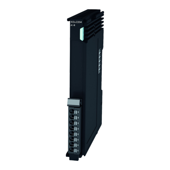
XI332204
The analog input terminal XI332204 processes signals in the
range from 0 to 20 mA in a ctrlX I/O station. The input signal
is digitized with a resolution of 16 bits and transferred galvan-
ically isolated to the system level. The 4 input channels are
differential inputs. Error states are shown at the channel LED
on the removable peripheral connector and routed to the con-
trol via the local bus.
The logic and peripheral supply as well as the EtherCAT-based
module communication are routed through the module.
For the integration into the parent system, the respective ESI
files are available. For the ESI files, go to ⮫ http://www.bos-
chrexroth.com/electrics.
Ensure
that
the
current
For the current documentations, go to ⮫ www.boschrex-
roth.com/mediadirectory.
Fig. 1: Module XI332204
2
Ordering data
Type
Part number Description
XI332204
R911406106 Analog input module, current
For more ordering data (accessories), go to the product cat-
alog under ⮫ www.boschrexroth.com/electrics.
3
Technical data
3.1 General technical data
XI332204
Number of inputs
4
Connection method Push-in
documentation
is
consulted.
between 0 and 20 mA
XI332204
Connection method 2-wire, shielded, twisted in pairs
Signal type
Differential
Input signal
0 mA to 20 mA
<250 Ω
Input resistance
Limit frequency of
15.7 kHz
input filter
100 μs
Conversion time
Resolution D/A
16 bits incl. sign
Typ. ± 0.1 % of the end value of the
Accuracy
measured range (MBE)
Max. ± 0.3% of MBE
Overload protection No, max. DC 10.4 V, I
Max. ±35 V compared to U
Common Mode
Voltage supply
U
P
Current consumption
40 mA
U
L
Current consumption
21 mA
U
P
Bit width, input data
18 bytes in the standard representation
in the process data
12 bytes in the "compact" representa-
image
tion
(including filling bit)
Can be set channel-granularly
Parameterization
Via ctrlX Works (start parameter)
Configuration
No address or configuration setting
required
Dimensions
12 mm × 105 mm × 99 mm (width ×
height × depth)
Weight
95 g (module including connector)
Electrical isolation
DC 1200 V U
FE
EMC resistance
Acc. to EN 61000-6-2 and EN 61000-6-4
Mounting position
Vertical, on a horizontal support rail
Labeling, approvals
CE, UKCA
3.2 Clamping point assignment
Clamping
Signal
point
1
AI Kanal 1+
2
AI Kanal 1-
3
AI Kanal 2+
4
AI Kanal 2-
5
AI Kanal 3+
6
AI Kanal 3-
7
AI Kanal 4+
8
AI Kanal 4-
3.3 Internal schematic diagram
System bus
µC
U
L
U
24 V
P
DC/DC
U
P
Fig. 2: Internal schematic diagram
R911418827
Edition 01
= 46 mA
max
GND
P
via jumper contacts
to U
, DC 707 V U
P
L
LED
Pusher
Red
Grey
None
Grey
Red
Grey
None
Grey
Red
Grey
None
Grey
Red
Grey
None
Grey
A/D
R911418827, Edition 01, 1 / 8
/U
to
P
L
AI_1
.
.
.
.
AI_4
Table of Contents

Related Manuals for Bosch Rexroth ctrlX I/O XI332204


Summary of Contents for Bosch Rexroth ctrlX I/O XI332204
- Page 1 ctrlX I/O Analog Input Terminal 4-channel, 0 to 20 mA, 16 Bit, Bipolar R911418827 DOK-XIO***-XI332204*AI-DA01-EN-P Edition 01 XI332204 XI332204 Connection method 2-wire, shielded, twisted in pairs The analog input terminal XI332204 processes signals in the Signal type Differential range from 0 to 20 mA in a ctrlX I/O station. The input signal is digitized with a resolution of 16 bits and transferred galvan- Input signal 0 mA to 20 mA...
-
Page 2: Signal Processing
3.4 Ambient conditions 4.2 User qualification The product use described in this data sheet is only intended XI342204 for qualified electricians and staff trained by these qualified Ambient temperature electricians. The user has to be familiar with the known safety Up to 4000 m -25 to 45 °C concepts on automation technology, applicable standards and... - Page 3 5.4 "Filter" and "Oversampling" Example 1: A first order low-pass filter in the hardware limits the fre- Module is XI422204, analog output with ±10 V. quency range at the input of the analog digital converter The target is to reduce the value range to values between (ADC).
-
Page 4: Object Directory
Object directory Index Object name Data type Access Unit Description (hex) 6.1 CoE standard objects 8000 Channel 1, 2, 3, 4 settings The object directory of the module contains objects that can 8010 8020 be triggered via SDO services. These are defined in the ETG standards: 8030 ‒... - Page 5 Word 1 Channel 1 Value Word 1 Channel 1 Value Word 2 Word 2 Channel 2 Value Byte 1 Word 3 Channel 3 Value Bit 0 Channel 1 Wire break Word 4 Channel 4 Value Word 5 Bit 1 Channel 1 Overrange Bit 2-3 Channel 1 Limit 1 Byte 1...
-
Page 6: Status Codes
Installation 8.2 Diagnosis history 10F3 The object 10F3hex is implemented as ring memory into the 9.1 Connection instructions "Overwrite mode". The latest 20 diagnostic messages are Differential input and potential reference stored. Older messages are deleted. The following table shows the structure of a diagnostic mes- For analog inputs, there are differential inputs without a refer- sage of the bus coupler for EtherCAT. -
Page 7: Installation Notes
– Additionally, provide sufficient distance for mounting, dis- mounting, plugs and cables. 24 V – If more devices are connected in series to the station on the left or right, the surface temperature may not exceed 60° C Input – In case of a several line design, the supply air has to be Input measured under each line and its limit value may not be... - Page 8 Remove the module vertically to the support rail [see (B) in the following figure]. R911418827 Bosch Rexroth AG Bgm.-Dr.-Nebel-Str. 2 97816 Lohr a.Main © Bosch Rexroth AG 2022 Germany Tel. +49 9352 18 0 Fax +49 9352 18 8400 DC-AE/EPI5 (AnBe/MaKo/MePe) www.boschrexroth.com/electrics...