Table of Contents
Table of Contents

Related Manuals for Bosch rexroth IndraControl XM21


Summary of Contents for Bosch rexroth IndraControl XM21
- Page 1 IndraControl XM21, XM22 Controls Operating Instructions Edition 04 R911340667...
- Page 2 Refer to chapter 1 "About this documentation" on page 1 Copyright © Bosch Rexroth AG 2019 All rights reserved, also regarding any disposal, exploitation, reproduction, edit- ing, distribution, as well as in the event of applications for industrial property rights.
-
Page 3: Table Of Contents
Bus base module for IndraControl S20 I/O........... SD card....................7 End clamp....................7 Wear parts..................... Ambient conditions................7 Technical data..................9 Voltage supply and current consumption..........Standards.................... Standards used..................11 CE marking................... 12 8.2.1 Declaration of conformity..............UL/CSA certified.................. 13 R911340667_Edition 04 Bosch Rexroth AG... - Page 4 12.1.1 LEDs in the XD1 plug................12.1.2 LED block of 10................... 12.1.3 Operation mode switches ..............37 12.1.4 Reset button..................12.2 XM2x initial firmware................39 12.2.1 License information................12.2.2 LED states.................... 40 12.2.3 Starting and opening the initial firmware..........Bosch Rexroth AG R911340667_Edition 04...
- Page 5 Error causes and troubleshooting............59 Maintenance..................14.1 Regular maintenance tasks..............Ordering information................15.1 Type code..................... 61 15.2 Accessories and spare parts..............62 Disposal....................16.1 General Information................62 16.2 Return....................62 16.3 Packaging..................... 62 Service and support................Index....................65 R911340667_Edition 04 Bosch Rexroth AG...
- Page 6 IndraControl XM21, XM22 Controls Bosch Rexroth AG R911340667_Edition 04...
-
Page 7: About This Documentation
Fig. 1-1: Assigning the present documentation to the target groups, product phases and ac- tivities of the target group This document instructs the technical staff of the machine manufacturer on how to safely perform the mechanical and electrical installation and on how to com- mission the device. R911340667_Edition 04 Bosch Rexroth AG... -
Page 8: Scope
Customer requests, comments or suggestions for improvement are of great im- portance to us. Please email your feedback on the documentations to Feed- [email protected]. Directly insert comments in the elec- tronic PDF document and send the PDF file to Bosch Rexroth. Bosch Rexroth AG R911340667_Edition 04... -
Page 9: Product Identification And Scope Of Delivery
I-C-B-H-T-V DC 24 V US LISTED 5 Fer IND.CONT.EQ 17YB 0,6 A SN: 7260007123456789 Bosch Rexroth AG, 97816 Lohr, Germany 6 Än 12 1 1 7 Sch Word mark Serial number Part number 10 Underwriters Laboratories Inc. mark Type name (type code) -
Page 10: Using Safety Instructions
Danger, Warning, Caution indicates hazards for persons. DANGER In case of non-compliance with this safety instruction, death or serious injury will occur. WARNING In case of non-compliance with this safety instruction, death or serious injury can occur. Bosch Rexroth AG R911340667_Edition 04... -
Page 11: Symbols Used
The same applies to cables and lines. Only to be operated with the component configurations and combinations ex- pressly defined and with the software and firmware specified in the correspond- ing functional description. R911340667_Edition 04 Bosch Rexroth AG... -
Page 12: Spare Parts, Accessories And Wear Parts
Part number Description S20-BS R911172540 Bus base module for wide IndraControl S20 I/O mod- ules S20-BS-S R911173203 Bus base module for narrow IndraControl S20 I/O mod- ules Tab. 5-3: Bus base modules for S20 I/O Bosch Rexroth AG R911340667_Edition 04... -
Page 13: Sd Card
Shock test acc. to DIN EN 60068-2-27 Shock stress: Shock resistance in all three axes, 11 ms semi-sinusoidal 30 g Broadband noise acc. to DIN EN 60068-2-64 5-20-150 Hz with 0.572 g, 5 h per axis R911340667_Edition 04 Bosch Rexroth AG... - Page 14 A (industrial environments), but not of class B (residential area and small enterprises). When using the product in residential areas or small enterprises, the operator has to take actions to prevent radio interferences (also re- fer to DIN EN 55022). Bosch Rexroth AG R911340667_Edition 04...
-
Page 15: Technical Data
18 V DC to 31.2 V DC (incl. all tolerances and rip- lowed U ple) Current consumption of the control incl. the con- Maximum 1.5 A nected S20 I/O modules from U at nominal volt- R911340667_Edition 04 Bosch Rexroth AG... -
Page 16: Standards
8 Standards The products have been developed according to the German edition of the standards published at the time of product engineering. Bosch Rexroth AG R911340667_Edition 04... -
Page 17: Standards Used
Automates programmables Partie 2: Spécifications et essais des équipements DIN EN 60529 Schutzarten durch Gehäuse (IP-Code) 2014 – Degrees of protection provided by enclosures (IP Code) – Degrés de protection procurés par les enveloppes (Code IP) R911340667_Edition 04 Bosch Rexroth AG... -
Page 18: Ce Marking
EU directive and with the following harmonized European standards: EMC directive 2014/108/EC The electronic products described in the present operating instructions are in- tended for use in industrial environments and comply with the following require- ments: Bosch Rexroth AG R911340667_Edition 04... -
Page 19: Ul/Csa Certified
UL and CSA marking applies only to the device upon delivery. After modifying the device, verify the UL and the CSA conformity. To guarantee an UL/CSA-compliant operation, the following condi- tions have to be fulfilled: Use only insulated copper wire suitable for at least 60/75°C ● R911340667_Edition 04 Bosch Rexroth AG... -
Page 20: Marine And Offshore Certification (Xm2201
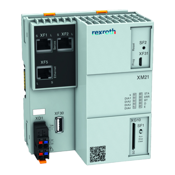
For more information, refer to www.boschrexroth.com/dcc/Vornavi- gation/VorNavi.cfm?PageID=p650746. 9 Interfaces 9.1 Connection position Fig. 9-1: Interfaces NOTICE Attaching and detaching connections under voltage can damage the control! Switch off the supply voltage before attaching or detaching any connections! Bosch Rexroth AG R911340667_Edition 04... -
Page 21: Extension Bus
IndraControl XM21, XM22 via S20 bus base modules. The number of connecta- ble modules depends on the total current consumption of the S20 modules. The IndraControl XM21, XM22 can provide up to 2 A for the power supply of the S20 modules. R911340667_Edition 04 Bosch Rexroth AG... -
Page 22: Control Bus Base Module
The fastening distance of the mounting rails may not exceed 200 mm. This distance is required to ensure stability while mounting and demounting the control or the S20 I/O modules. < 200 Fig. 10-1: Mounting rail fastening (in mm) Bosch Rexroth AG R911340667_Edition 04... - Page 23 The cabling of the Ethernet wires may not leave the building ● The LED displays on the operating panel must not be covered ● Observe the bending radius of the cables used when laying the connecting ● lines Use strain reliefs for all cables ● R911340667_Edition 04 Bosch Rexroth AG...
- Page 24 6 "Ambient conditions" on page 7 Additionally, provide sufficient distance for mounting, demounting, plugs and ● cables. For more information on mounting, demounting and connecting lines, refer to the application description "IndraControl S20: System and Installation", part no. R911335990. Bosch Rexroth AG R911340667_Edition 04...
-
Page 25: Housing Dimensions
Fig. 10-4: Front view Fig. 10-5: Bottom view 10.3 Mounting the control NOTICE Damages at the contacts by tilting the modules Attach the modules vertically on the mounting rail and remove them vertically from the mounting rail. R911340667_Edition 04 Bosch Rexroth AG... - Page 26 Install the control in a control cabinet or an appropriate housing ● Mounting the control bus base module 1. Press the control bus base module on the top-hat rail until all latchings are safely closed. Fig. 10-7: Mounting the bus base module Bosch Rexroth AG R911340667_Edition 04...
-
Page 27: Mounting S20 I/O Modules
S20 bus base module with the bus base module of the control (see (D) in the following figure). 3. Move the other S20 bus base modules to the left until all bus base modules are interconnected (see (C) in the following figure). R911340667_Edition 04 Bosch Rexroth AG... -
Page 28: Mounting Extension Modules
1. Press the extension bus base modules for the extension modules on the top-hat rail on the left next to the control bus base module until all latch- ings are safely closed (see (A) in the following figure). Bosch Rexroth AG R911340667_Edition 04... -
Page 29: Demounting The Control And The Control Bus Base Module
Removing the control from the top-hat rail 1. Remove the left end clamp. 2. Use a suitable tool (e.g. slotted screwdriver) and put it first into the upper and then into the lower disengaging mechanism (base latch) of the control R911340667_Edition 04 Bosch Rexroth AG... - Page 30 3. Use a suitable tool (e.g. slotted screwdriver) to enter into the latchings on one side (see (B), (B1), (B2) in the following figure). 4. Lift up the bus base module and remove it (see (C) in the following figure). Bosch Rexroth AG R911340667_Edition 04...
-
Page 31: Electric Installation
Note the over- voltage categories (refer to the documentation of the power supply unit) Do not apply the supply voltage to the protective extra-low voltage ● All control components are supplied from 24 V voltage supplies (SELV/PELV). R911340667_Edition 04 Bosch Rexroth AG... -
Page 32: Voltage Supply For The Control
IndraControl XM21, XM22 Controls Mounting, demounting and electric installation Use the Bosch Rexroth power supply unit VAP01.1H-W23-024-010-NN, part num- ber R911171065, for the logic supply. For further information on the external power supply unit and on the creation of overvoltage categories, refer to the documentation of the power supply unit. -
Page 33: Voltage Supply
An easy connection method is the setup without an electrical isolation between the internal logic and the peripheral supply. In this case, a power supply unit is sufficient to supply the control. The GND (U ) is grounded in the device! R911340667_Edition 04 Bosch Rexroth AG... - Page 34 I/O interfaces of the peripheral component groups according to DIN EN 60204-1. Accordingly, the voltage U (24 V logic voltage) at the control is elec- trically isolated from the supply voltage for the I/O modules. Bosch Rexroth AG R911340667_Edition 04...
-
Page 35: Grounding
Hence, the supply current circuit is a PELV circuit. 10.7.4 Grounding NOTICE Control failure due to insufficient grounding An optimum grounding is required to keep away possible interferences from the control and to discharge them to the ground. R911340667_Edition 04 Bosch Rexroth AG... -
Page 36: Shielding
Note the wire specifications when connecting the shielding ● Shield the closest possible to the signal terminal points ● Route all power cables and data cables in separate cable channels. 11 Commissioning 11.1 Commissioning steps To commission the device, proceed as follows: Bosch Rexroth AG R911340667_Edition 04... -
Page 37: Establishing A Connection To The Engineering Pc Via The Usb Device Interface "Xf31
(e.g. monitoring). The IP address of the connection "XF31" on the control is 192.168.234.234. The IP address cannot be changed. If the RNDIS device driver is not installed automatically, install it manually: R911340667_Edition 04 Bosch Rexroth AG... - Page 38 3. Select "Update driver software..." in the context menu of "RNDIS/Ethernet gadget". 4. In the dialog, select the entry: "Browse my computer for driver software". 5. In the dialog, select the entry: "Let me pick from a list of device drivers in my computer". Bosch Rexroth AG R911340667_Edition 04...
- Page 39 IndraControl XM21, XM22 Controls 33/69 Commissioning 6. In the dialog, select the entry: "Network adapters". 7. Select the entry "Microsoft corporation" under "Manufacturer". Then, se- lect "Remote NDIS compatible device" under "Network adapter". R911340667_Edition 04 Bosch Rexroth AG...
-
Page 40: Device Description
8. To confirm the installation, click on "Yes". 9. After a successful installation, the following message is displayed: 12 Device description The XM2x controls are compact controls in the medium-performance range with integrated interfaces of Ethernet, Sercos and S20 local bus. Bosch Rexroth AG R911340667_Edition 04... -
Page 41: Leds And Operating Elements
LEDs on power connector XD1 Fig. 12-1: LED and operating element positions 12.1.1 LEDs in the XD1 plug Fig. 12-2: LEDs on the XD1 plug The following functions are assigned to the LEDs on the XD1 plug: R911340667_Edition 04 Bosch Rexroth AG... -
Page 42: Led Block Of 10
Tab. 12-1: LED functions on the XD1 plug 12.1.2 LED block of 10 XF31 DIA1 DIA2 IndraControl XM21 DIA3 DIA4 DIA1 DIA2 DIA3 DIA4 XG10 XF30 Stop Clear UL T 24V 0V USV 0V Fig. 12-3: LED block of 10 Bosch Rexroth AG R911340667_Edition 04... -
Page 43: Operation Mode Switches
(Rexroth IndraLogic XLC IndraMotion MLC 14 VRS, Functional De- scription, R911341700). 12.1.3 Operation mode switches The operation mode switch is positioned on the higher located area of the con- trol housing. R911340667_Edition 04 Bosch Rexroth AG... -
Page 44: Reset Button
Refer to the functional description of the respective control system (Rexroth IndraLogic XLC IndraMotion MLC 14 VRS, Functional Description, R911341700) 12.1.4 Reset button The "Reset" button is positioned on the higher located area of the control hous- ing. Bosch Rexroth AG R911340667_Edition 04... -
Page 45: Xm2X Initial Firmware
SF1 and the LED display panel. The commissioning tool "IndraControl First Touch" (see chapter 12.3 "IndraControl First Touch" on page 43) provides a more comfortable operation R911340667_Edition 04 Bosch Rexroth AG... -
Page 46: License Information
(ii) in the case of code licensed under the GPL v3 for as long as Bosch Rexroth offers spare parts or customer support for that product. -
Page 47: Starting And Opening The Initial Firmware
24 V supply voltage until the LEDs DIA3 and DIA4 flash alternatingly in red. Sub- sequently, one of the following functions can be opened via a menu structure: Menu item number Functions Color Start First Touch Start First Touch, delete network configuration R911340667_Edition 04 Bosch Rexroth AG... - Page 48 We recom- mend to create a system firmware backup (see chapter 12.3.3 "Firmware management" on page 45) before using this function. The initial firmware is part of the hardware and not deleted. Bosch Rexroth AG R911340667_Edition 04...
-
Page 49: Installing A Backup From An External Sd Card
If the control is as in delivery state, a backup can also be loaded to the control without PC. Proceed as follows: 1. Copy a valid control backup to a Bosch Rexroth SD card (part no. 1070925435). Create a control backup using a PC with an SD card reader or use the file manager of the First Touch commissioning tool. -
Page 50: Hardware Data
The "Network" site of the IndraControl First Touch is used to configure the net- work settings during the initial commissioning. The currently configured network settings are shown in the following three fields and can also be changed using these fields: IP address ● Bosch Rexroth AG R911340667_Edition 04... -
Page 51: Firmware Management
It is used to restart the control and thus applies the network setting. Fig. 12-7: "Network configuration" dialog The network settings are only applied after a control restart. 12.3.3 Firmware management The "Firmware management" site of the IndraControl First Touch provides the following information: R911340667_Edition 04 Bosch Rexroth AG... - Page 52 A ".fw" file is stored on the user partition of the control after the process. This file can be loaded to a local PC at a later point in time (see chapter 12.3.4 "File manager" on page 51). Bosch Rexroth AG R911340667_Edition 04...
- Page 53 ".fw". The backup can only be started if the selected file name corre- sponds to the archive rules. During as well as after the backup, a corresponding message is displayed. Fig. 12-9: Dialog "Archive SYSTEM|OEM|USER" R911340667_Edition 04 Bosch Rexroth AG...
- Page 54 If the system archive file is selected from the local file system, the archive is installed in two steps: 1. Transferring the system archive file to the control 2. Installing the archive Bosch Rexroth AG R911340667_Edition 04...
- Page 55 IndraControl XM21, XM22 Controls 49/69 Device description Fig. 12-11: Dialog "Restore SYSTEM|OEM|USER" – Upload R911340667_Edition 04 Bosch Rexroth AG...
- Page 56 50/69 IndraControl XM21, XM22 Controls Device description Fig. 12-12: Dialog "Restore SYSTEM|OEM|USER" – Installation running Fig. 12-13: Dialog "Restore SYSTEM|OEM|USER" – Successfully completed Bosch Rexroth AG R911340667_Edition 04...
-
Page 57: File Manager
Transfer files from the client to the control (action: Upload file) ● Create directories (action: Create directory) ● Delete (empty) directories (click on the "Delete" icon in the table row) ● Delete files (click on the "Delete" icon in the table row) ● R911340667_Edition 04 Bosch Rexroth AG... -
Page 58: Core Dump
(e.g. not sufficient free memory space available). Un this case, storage space can be released in the default target directory for core dump files (/USER/). Use the "File manager" menu item. An addi- Bosch Rexroth AG R911340667_Edition 04... -
Page 59: Booting
3. The LEDs "DIA3" and "DIA4" in the LED block of 10 flash alternatingly in red while booting. 4. The LEDs "DIA3" and "DIA4" in the LED block of 10 go off after booting and when the operating system is running. R911340667_Edition 04 Bosch Rexroth AG... -
Page 60: Fallback And Recovery
24 V supply voltage failure and restored at control startup. 12.7 Real-time clock The real-time clock of the control is buffered in the switched-off state. The buf- fer capacitor looses efficiency when operated permanently at high tempera- Bosch Rexroth AG R911340667_Edition 04... -
Page 61: Real-Time Response
It is recommended to configure the maximum processing time permitted (watch- dog) for each PLC task within an application. The maximum permitted process- ing time is configured in the task configuration of the PLC. R911340667_Edition 04 Bosch Rexroth AG... - Page 62 It is additionally possible to execute a customized code once and as soon as the error is detected. Define a respective event handler in the task configuration. Fig. 12-19: Adding event handlers Select “Exception” as event. Bosch Rexroth AG R911340667_Edition 04...
- Page 63 Fig. 12-21: Specifying the function name The POU watchdog is created in the project tree and the event handler is ena- bled. Program the analysis of the exception code (as shown in the following fig- ure) and your user code. R911340667_Edition 04 Bosch Rexroth AG...
-
Page 64: Programming Example: Cyclic Monitoring Of The Cpu Load
PLC. Example: Cyclic analysis of the CPU load in the PLC user program Fig. 12-23: Definition of a global variable, e.g. "gboOverload" to display an invalid ex- ceedance of the CPU load Bosch Rexroth AG R911340667_Edition 04... -
Page 65: Error Causes And Troubleshooting
Further operating displays and error displays are located on the individual mod- ules and terminals. For information on the other displays, refer to the manual of the IndraControl S20 component (see also chapter 1.3 "Related documents" on page R911340667_Edition 04 Bosch Rexroth AG... -
Page 66: Maintenance
Maintenance work in the device is only permis- sible by skilled staff! If hardware or software components have to be exchanged, please contact the Bosch Rexroth Service or ensure that only skilled staff changes the respective components. 14.1 Regular maintenance tasks... -
Page 67: Type Code
EtherCAT - Master....................= 1 Communication (Function package) None..........................= N OPC UA........................= 1 OCI..........................= 2 OPC UA + OCI ......................= 3 None..........................= N JAVA ..........................= 1 JAVA + WebConnector....................= 2 Reserve None...........................= N Fig. 15-1: Type code R911340667_Edition 04 Bosch Rexroth AG... -
Page 68: Accessories And Spare Parts
The packaging material consists of cardboard, plastics, wood or styrofoam. Packaging material can be recycled anywhere. For ecological reasons, please do not return empty packages to Bosch Rexroth. 17 Service and support Our worldwide service network provides an optimized and efficient support. - Page 69 Detailed description of malfunction and circumstances ● Type plate specifications of the affected products, in particular type codes ● and serial numbers Your contact data (phone and fax number as well as your e-mail address) ● R911340667_Edition 04 Bosch Rexroth AG...
- Page 70 64/69 IndraControl XM21, XM22 Controls Bosch Rexroth AG R911340667_Edition 04...
-
Page 71: Index
Disposal........62 Distances........18 Distances for cooling....18 LED block of 10......36 Documentation LED states........40 Change record......1 LEDs..........35 Documents, related......2 LEDs in XD1 plug......35 License information...... 40 Electric Installation....... 25 R911340667_Edition 04 Bosch Rexroth AG... - Page 72 Reset button......... 38 XD1, LEDs........35 Restore SYSTEM|OEM|USER..48 XF31........31, 60 RNDIS device driver...... 31 S20 I/O modules, mounting..21 S20 interface........ 15 Safety instructions......4 Scope of delivery......3 SD Card.......... 7 Service hotline......62 Bosch Rexroth AG R911340667_Edition 04...
- Page 73 IndraControl XM21, XM22 Controls 67/69 R911340667_Edition 04 Bosch Rexroth AG...
- Page 74 68/69 IndraControl XM21, XM22 Controls Bosch Rexroth AG R911340667_Edition 04...
- Page 75 IndraControl XM21, XM22 Controls 69/69 Notes...
- Page 76 Bosch Rexroth AG Electric Drives and Controls P.O. Box 13 57 97803 Lohr, Germany Bgm.-Dr.-Nebel-Str. 2 97816 Lohr, Germany Phone +49 9352 18 0 Fax +49 9352 18 8400 www.boschrexroth.com/electrics *R911340667* R911340667 DOK-CONTRL -IC*XM2*****-IT04-EN-P...