Bosch rexroth IndraControl XFE 01.1 Operating Instructions Manual
Extension modules profibus, rt-ethernet, sercos, can
Hide thumbs
Also See for rexroth IndraControl XFE 01.1:
- Operating instructions manual (44 pages) ,
- Operating manual (36 pages)

Related Manuals for Bosch rexroth IndraControl XFE 01.1


Summary of Contents for Bosch rexroth IndraControl XFE 01.1
- Page 1 IndraControl XFE 01.1 Extension Modules Profibus, RT-Ethernet, Sercos, CAN Operating Instructions Edition 05 R911345570...
- Page 2 2019-06 Refer to tab. 1-1 "Change Record" on page 1 Copyright © Bosch Rexroth AG 2019 All rights reserved, also regarding any disposal, exploitation, reproduction, editing, distribution, as well as in the event of applications for industrial property rights. Liability...
-
Page 3: Table Of Contents
End clamp....................6 Wear parts..................... Ambient conditions................7 Technical data..................8 Voltage supply and current consumption..........Standards....................Standards used..................9 CE marking................... 10 8.2.1 Declaration of conformity..............UL/CSA certified.................. 10 Marine and offshore certification (XFE01.1-FB-03, XFE01.1-FB-20)..11 R911345570_Edition 05 Bosch Rexroth AG... - Page 4 General information................25 14.2 Regular maintenance tasks..............Ordering information................15.1 Type code..................... 26 15.2 Accessories and spare parts..............27 Disposal....................16.1 General information................27 16.2 Return....................27 16.3 Packaging..................... 27 Service and support................Index....................29 Bosch Rexroth AG R911345570_Edition 05...
-
Page 5: About This Documentation
Program Test Maintain Dispose Activities Design Install Configure Remove faults Construct Simulate Create the NC program Fig. 1-1: Assigning the present documentation to the target groups, product phases and ac- tivities of the target group R911345570_Edition 05 Bosch Rexroth AG... -
Page 6: Scope
Customer requests, comments or suggestions for improvement are of great importance to us. Please email your feedback on the documentations to [email protected]. Directly insert comments in the electronic PDF document and send the PDF file to Bosch Rexroth. Bosch Rexroth AG R911345570_Edition 05... -
Page 7: Product Identification And Scope Of Delivery
2.1 Product identification and type plate 2 3 4 IndraControl XFE MNR: R911172531 -AA0 7260 FW: 101 FI: 001 SN: 7260007123456BC FD: 12W16 Bosch Rexroth AG, Bgm.-Dr.-Nebel-Str. 2 Functional Safety DE-97816 Lohr Hotline: +49 9352 405060 Type Approved www.tuv.com Made in Germany... -
Page 8: Using Safety Instructions
Danger, Warning, Caution indicates hazards for persons. DANGER In case of non-compliance with this safety instruction, death or serious injury will occur. WARNING In case of non-compliance with this safety instruction, death or serious injury can occur. Bosch Rexroth AG R911345570_Edition 05... -
Page 9: Symbols Used
Components that are not expressly mentioned must neither be attached nor connected. The same applies to cables and lines. Only to be operated with the component configurations and combinations expressly defined and with the software and firmware specified in the corresponding functional description. R911345570_Edition 05 Bosch Rexroth AG... -
Page 10: Spare Parts, Accessories And Wear Parts
2 pieces of snap-on end brackets for 35 mm NS 35/7.5 or NS 35/15 carrier plate; width: 9.5 mm Tab. 5-4: End clamp 5.5 Wear parts There are no wear parts in the extension modules. Bosch Rexroth AG R911345570_Edition 05... -
Page 11: Ambient Conditions
The devices to be installed into the housing and installation compartments ● must at least comply with the degree of protection IP 54 according to DIN EN 60529. The device shall be provided in a suitable fire enclosure in the end-use ● application. R911345570_Edition 05 Bosch Rexroth AG... -
Page 12: Technical Data
Voltage dips at current supply interfaces Up to 10 ms without impairment Electrical isolation and isolation of the voltage ranges Profibus extension module 24 V supply with FE to XF8 1,200 V DC, 1 min. Bosch Rexroth AG R911345570_Edition 05... -
Page 13: Standards
Degrees of protection provided by enclosures (IP Code) 2014 IEC 61010-2-201 Safety requirements for electrical equipment for 2014 measurement, control and laboratory use UL 61010-2-201 Safety requirements for electrical equipment for 2014 measurement, control and laboratory use Tab. 8-1: Standards used R911345570_Edition 05 Bosch Rexroth AG... -
Page 14: Ce Marking
CSA C22.2 NO. 61010-1-12 UPDATE – Edition 3 ● CSA C22.2 NO. 61010-2-201:14 – Edition 1 However, there can be combinations or extension stages with a limited or missing certification. Thus, verify the registration according to the UL marking on the device. Bosch Rexroth AG R911345570_Edition 05... -
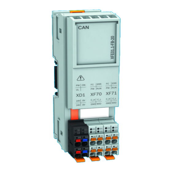
Page 15: Marine And Offshore Certification (Xfe01.1-Fb-03, Xfe01.1-Fb-20)
RINA Registro Italiano Navale DCTC_30826-003 ● LR Lloyd's Register DCTC_30826-004 ● BV Bureau Veritas DCTC_30826-005 ● BSH Bundesamt für Seeschifffahrt und Hydrographie DCTC 30826-006 ● more information, refer www.boschrexroth.com/dcc/ Vornavigation/VorNavi.cfm?PageID=p669155. 9 Interfaces Fig. 9-1: Interfaces of the extension modules R911345570_Edition 05 Bosch Rexroth AG... - Page 16 Adding the termination resistor to the CAN network The resistor is enabled by connecting the plug contacts 10 (CAN GND) and 11 (WID) or 12 (CAN GND) and 13 (WID). Tab. 9-2: Pin assignment of XF70 and XF71 Bosch Rexroth AG R911345570_Edition 05...
-
Page 17: Mounting, Demounting And Electric Installationi
10.1 Housing dimensions 54.8 * 41.6 50.8 52.4 ② The dimensions depend on the respec- Mounting rail center tive extension module ① Mounting rail TH 35 – 7,5 acc. to DIN EN 60715 Fig. 10-1: Housing dimensions R911345570_Edition 05 Bosch Rexroth AG... -
Page 18: Installation Notes
If screws and rivets are too high on the mounting rail, the bus base modules do not really engage on the mounting rail. Use only screws and rivets with a structural height of up to 3 mm to fasten the mounting rail. End clamp ● Bosch Rexroth AG R911345570_Edition 05... - Page 19 XM control, see fig. 10-3 "Minimum distances for the circulation of ambient air" on page 15 100 mm 30 mm 30 mm 30 mm 100 mm Fig. 10-3: Minimum distances for the circulation of ambient air R911345570_Edition 05 Bosch Rexroth AG...
-
Page 20: Mounting
Connect the voltage only after the control and its components have been set ● The extension bus base modules can only be mounted if the control is not attached to the control bus base module. Bosch Rexroth AG R911345570_Edition 05... -
Page 21: Demounting
Removing extension module from top-hat rail 1. Remove the left end clamp. 2. Use a suitable tool (e.g. slotted screwdriver) and put it first into the upper and then into the lower disengaging mechanism (base latch) of the control R911345570_Edition 05 Bosch Rexroth AG... -
Page 22: Electric Installation
10.5.1 External power supply unit All control components are supplied from 24 V voltage supplies. Use the Bosch Rexroth power supply unit VAP01.1H-W23-024-010-NN, part number R911171065, for the logic supply. For further information on the external power supply unit and on the creation of overvoltage categories, refer to the documentation of the power supply unit. - Page 23 10-7 "Mandatory voltage supply" on page 19. Other connection variants are not permitted. 24 V ① ④ 24 V voltage supply XM2x control ② ⑤ Top-hat rail S20 Module ③ Extension module Fig. 10-7: Mandatory voltage supply R911345570_Edition 05 Bosch Rexroth AG...
-
Page 24: Voltage Supply For The Control And For The Extension Modules
Connect the power connector with cables with a conductor cross- section of AWG 16 (1.5 mm Observe the color-coding of the plugs. Only the "XA-CN01" power connector is permitted to connect the 24 V supply voltage (see chapter 5.1 "Connector 24 V" on page Bosch Rexroth AG R911345570_Edition 05... -
Page 25: Voltage Supply
In case of an error, the display LED is not on, refer to chapter 13 "Error causes and troubleshooting" on page 12 Device description Use the extension modules "Sercos", "Profibus", "Profinet" and "CAN" for a field bus with the same name at a control. R911345570_Edition 05 Bosch Rexroth AG... -
Page 26: Leds
LED is permanently on: No connection LED flashes: Slave diagnostics Sercos extension module Orange LED is cyclically on: Data is sent Green LED is permanently on: Connection present CAN extension module Green LED is permanently on: CAN voltage present Bosch Rexroth AG R911345570_Edition 05... -
Page 27: Led On Xd1 Plug
Internal voltage error: Voltage transformer is defective ● 24 V supply voltage is not connected ● 24 V supply voltage is connected with reverse ● polarity LED is off Internally programmed function block is not loaded R911345570_Edition 05 Bosch Rexroth AG... -
Page 28: Error Cases After Commissioning The Can Module
If the display LED "ON" is not on at the control XMxx, press the “Fallback” pushbutton of the CAN module. Proceed the following step. 4. Initiate the "Fallback mode" for the extension modules, whose display LED "ON" is not on: Bosch Rexroth AG R911345570_Edition 05... -
Page 29: Maintenance
If hardware or software components have to be exchanged, please contact the Bosch Rexroth Service or ensure that only skilled staff changes the respective components. 14.2 Regular maintenance tasks Include the following measures into the maintenance schedule: Check all plug and terminal connections of the components for proper ●... -
Page 30: Ordering Information
CAN master 4 x (passive) ......= 22 CAN slave 4 x (passive) ....... = 23 Safety Safe Logic to SIL3 ........= 01 Note: 1) Function type “SY” only available with function Safety “01” Fig. 15-1: Type code Bosch Rexroth AG R911345570_Edition 05... -
Page 31: Accessories And Spare Parts
The packaging material consists of cardboard, plastics, wood or styrofoam. Packaging material can be recycled anywhere. For ecological reasons, please do not return empty packages to Bosch Rexroth. 17 Service and support Our worldwide service network provides an optimized and efficient support. - Page 32 Detailed description of malfunction and circumstances ● Type plate specifications of the affected products, in particular type codes ● and serial numbers Your contact data (phone and fax number as well as your e-mail address) ● Bosch Rexroth AG R911345570_Edition 05...
-
Page 33: Index
Electric installation....13, 18 Return........... 27 Emitted interference....... 8 End clamp......... 6, 14 Error causes........23 Safety instructions......4 Scope of delivery......3 Service hotline......27 Feedback........2 Signal alert symbol......4 Signal words........4 R911345570_Edition 05 Bosch Rexroth AG... - Page 34 Suggestions........2 Support........27 Symbols.......... 5 Target groups........1 Technical data......... 8 Troubleshooting......23 Type code........26 Type plate........3 UL/CSA certified......10 Use, intended........5 Voltage supply..... 8, 20, 21 Warnings......... 4 Wear parts........6 Bosch Rexroth AG R911345570_Edition 05...
- Page 35 IndraControl XFE 01.1 Extension Mod- 31/31 ules Profibus, RT-Ethernet, Sercos, CAN Notes...
- Page 36 Bosch Rexroth AG Electric Drives and Controls P.O. Box 13 57 97803 Lohr, Germany Bgm.-Dr.-Nebel-Str. 2 97816 Lohr, Germany Phone +49 9352 18 0 Fax +49 9352 18 8400 www.boschrexroth.com/electrics *R911345570* R911345570 DOK-CONTRL -XFE**EXTMOD-IT05-EN-P...