Table of Contents
Quick Links
IndraControl
XM21, XM22
Controls
LSA Control S.L. www.lsa-control.com [email protected] (+34) 960 62 43 01
Operating Instructions
R911340667
Edition 03
Table of Contents

Related Manuals for Bosch Rexroth IndraControl XM21


Summary of Contents for Bosch Rexroth IndraControl XM21
- Page 1 IndraControl XM21, XM22 Controls Operating Instructions Edition 03 R911340667 LSA Control S.L. www.lsa-control.com [email protected] (+34) 960 62 43 01...
- Page 2 © Bosch Rexroth AG 2017 This document, as well as the data, specifications and other information set forth in it, are the exclusive property of Bosch Rexroth AG. It may not be repro- duced or given to third parties without its consent.
-
Page 3: Table Of Contents
Controls Bosch Rexroth AG Table of Contents Table of Contents Page About this documentation..............Overview on target groups and product phases........1 Scope..................... 1 Related documents................2 Customer feedback................2 Product identification and scope of delivery......... 2 Product identification................2 Scope of delivery................... - Page 4 Bosch Rexroth AG Controls Table of Contents Page 8.4.1 Power matrix..................13 8.4.2 Standards used..................13 Marine and offshore certification (XM2201...)........Interfaces..................... 14 Connection position................Extension bus..................S20 interface..................Control bus base module ..............15 Mounting, demounting and electric installation........
- Page 5 Controls Bosch Rexroth AG Table of Contents Page 12.2.2 LED states.................... 39 12.2.3 Starting and opening the initial firmware..........12.2.4 Installing a backup from an external SD card........12.3 Booting....................12.4 Fallback and recovery................12.5 IndraControl First Touch..............43 12.5.1 Hardware data..................
- Page 6 Bosch Rexroth AG Controls DOK-CONTRL -IC*XM2*****-IT03-EN-P LSA Control S.L. www.lsa-control.com [email protected] (+34) 960 62 43 01...
-
Page 7: About This Documentation
Controls Bosch Rexroth AG About this documentation 1 About this documentation 1.1 Overview on target groups and product phases In the following illustration, the framed activities, product phases and target groups refer to the present documentation. Example: In the product phase "Mounting (assembly/installation)", the target group "mechanic/electrician"... -
Page 8: Related Documents
Please email your feedback on the documentations to Feed- [email protected]. Directly insert comments in the elec- tronic PDF document and send the PDF file to Bosch Rexroth. 2 Product identification and scope of delivery 2.1 Product identification... -
Page 9: Scope Of Delivery
Controls Bosch Rexroth AG Use of the safety instructions Date of manufacture (yyWww) 12 Nominal current State of revision 13 Nominal voltage CE conformity marking 14 Company address Plant number 15 MAC address, MAC address as barcode QR code 16 Functional index... -
Page 10: Symbols Used
Bosch Rexroth AG Controls Use of the safety instructions DANGER In case of non-compliance with this safety instruction, death or serious injury will occur. WARNING In case of non-compliance with this safety instruction, death or serious injury can occur. CAUTION In case of non-compliance with this safety instruction, minor or moderate injury can occur. -
Page 11: Intended Use
Controls Bosch Rexroth AG Spare parts, accessories and wear parts 4 Intended Use NOTICE Danger of device damage if not the expressly stated accessories, mounting parts, compo- nents, cables, lines, software and firmware are used. The IndraControl XM21/XM22 control may only be used with the accessories and mounting parts listed in this documentation. -
Page 12: Bus Base Module For Indracontrol Xm21/Xm22
Bosch Rexroth AG Controls Ambient conditions 5.2 Bus base module for IndraControl XM21/XM22 Ordering code Part number Description XA-BS01 R911342346 Bus base module for IndraControl S20 connection (right) XA-BS02 R911342347 Bus base module for IndraControl S20 connection (right) and extension modules (left) Tab. - Page 13 Controls Bosch Rexroth AG Ambient conditions Operating altitude Up to 4,700 m above sea level acc. to DIN 60204 Permitted air humidity 5 % to 95 % acc. to DIN EN 61131-2, no conden- sation Degree of protection IP20 acc. to DIN EN 60 529...
-
Page 14: Technical Data
Bosch Rexroth AG Controls Technical data NOTICE Failure of the product due to overheating To avoid overheating and to ensure a smooth operation of the product according to the minimum distances specified in chapter 10.1 "Installation notes" on page 16, air has to circulate. -
Page 15: Voltage Supply And Current Consumption
Controls Bosch Rexroth AG Standards Weight 0.38 kg (incl. supply connectors) Dimensions Refer to chapter 10.2 "Housing dimensions" on page 18 Tab. 7-1: Technical data 7.1 Voltage supply and current consumption The following values apply to the operating voltage acc. to DIN EN 61131-2:... -
Page 16: Standards Used
Bosch Rexroth AG Controls Standards 8.1 Standards used Standard Meaning Edition IEC 60204-1 Electrical equipment of machines 2007 IEC 61131-2 Programmable controllers 2008 IEC 60529 Degrees of protection provided by enclosures (IP Code) 2014 IEC 61010-2-201 Safety requirements for electrical equipment for measure-... -
Page 17: Explosion Protection Certification (Xm2201.01
Controls Bosch Rexroth AG Standards The devices are certified acc. to UL 61010-2-201 (Industrial Control Equipment) and ● CSA22.2 No. 61010-2-201 (CSA) ● However, there can be combinations or extension stages with a limited or miss- ing certification. Thus, verify the registration according to the UL marking on the device. - Page 18 XM2201.01-..The explosion protection approval is only valid if the devices and ● components approved by Bosch Rexroth are used as intended, re- fer to chapter 4 "Intended Use" on page The XM22 control may only be used together with the additional ●...
-
Page 19: Power Matrix
Controls Bosch Rexroth AG Standards 8.4.1 Power matrix Devices and com- Max. internal current consumption Max. internal power consumption ponents XM2201.01.-..1500 mA 36.0 W R911173148 XFE01.1-FB-03 200 mA 4.8 W R911173397 XFE01.1-FB-20 200 mA 4.8 W R911173957 S20-AI6-AO2- 100 mA 2.4 W... -
Page 20: Interfaces
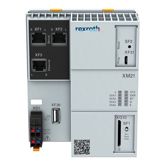
Bosch Rexroth AG Controls Interfaces BSH Bundesamt für Seeschifffahrt und Hydrographie DCTC 30826-006 ● For more information, refer to www.boschrexroth.com/dcc/Vornavi- gation/VorNavi.cfm?PageID=p650746. 9 Interfaces 9.1 Connection position Fig. 9-1: Interfaces NOTICE Attaching and detaching connections under voltage can damage the control! -
Page 21: Extension Bus
Controls Bosch Rexroth AG Interfaces Name Connection type Connector type Mating connector and cable (Integrated) (From outside) S20 bus Bus base module Bus base module for S20 I/O ④ modules 32-pin 32-pin Slot for SD card – SD card ⑤... -
Page 22: Mounting, Demounting And Electric Installation
Bosch Rexroth AG Controls Mounting, demounting and electric installation Depending on the function package, one of the bus base modules (XA-BS01 or XA-BS02) is included upon delivery (see chapter 5 "Spare parts, accessories and wear parts" on page 10 Mounting, demounting and electric installation 10.1 Installation notes... - Page 23 Controls Bosch Rexroth AG Mounting, demounting and electric installation End clamps guarantee the correct fastening of the XM2x control and the S20 I/O modules connected to them on the mounting rail and they are used as lat- eral end elements.
-
Page 24: Housing Dimensions
Bosch Rexroth AG Controls Mounting, demounting and electric installation In case of a several line design, the supply air has to be measured under each line and its limit value has to be observed. For information on ambient tem- peratures, refer to chapter 6 "Ambient conditions"... -
Page 25: Mounting The Control
Controls Bosch Rexroth AG Mounting, demounting and electric installation 10.3 Mounting the control NOTICE Damages at the contacts by tilting the modules Place the modules vertically on the mounting rail and remove them vertically from the mounting rail as well. -
Page 26: Mounting S20 I/O Modules
Bosch Rexroth AG Controls Mounting, demounting and electric installation Fig. 10-6: Mounting the bus base module 2. Mount the S20 bus base module as shown in fig. 10-8 "Connect S20 bus base modules among each other and with the control bus base module" on... -
Page 27: Mounting Extension Modules
Controls Bosch Rexroth AG Mounting, demounting and electric installation 3. Move the other S20 bus base modules to the left until all bus base modules are connected with each other (see (C) in the following figure). Fig. 10-8: Connect S20 bus base modules among each other and with the control bus... -
Page 28: Demounting The Control And The Control Bus Base Module
Bosch Rexroth AG Controls Mounting, demounting and electric installation Mounting extension bus base modules 1. Press the extension bus base modules for the extension modules on the top-hat rail on the left next to the control bus base module until all latch- ings are safely closed (see (A) in the following figure). - Page 29 Controls Bosch Rexroth AG Mounting, demounting and electric installation Removing the control from the top-hat rail 1. Remove the left end clamp. 2. Use a suitable tool (e.g. slotted screwdriver) and put it first into the upper and then into the lower disengaging mechanism (base latch) of the control and disengage the control (see (A) in the following figure).
-
Page 30: Electric Installation
Bosch Rexroth AG Controls Mounting, demounting and electric installation Fig. 10-12: Removing the control bus base module from the top-hat rail 10.7 Electric installation WARNING Danger of personal injury due to incorrect mounting or electric installation! Any dangerous system states, which might cause personal injury, must be pre- ●... -
Page 31: Voltage Supply For The Control
Bosch Rexroth AG Mounting, demounting and electric installation Use the Bosch Rexroth power supply unit VAP01.1H-W23-024-010-NN, part num- ber R911171065, for the logic supply. For further information on the external power supply unit and on the creation of overvoltage categories, refer to the documentation of the power supply unit. -
Page 32: Voltage Supply
Bosch Rexroth AG Controls Mounting, demounting and electric installation If multiple XM2x controls (24 V supply voltage U ) are connected parallely to a central 24 voltage supply, ensure that the 0 V connec- tion of the U is wired without interruption to all XM2x controls. - Page 33 Controls Bosch Rexroth AG Mounting, demounting and electric installation Overvoltage category I, 24 V Power supply unit 24 V 7071 7273 7475 7677 4243 4647 0001 0405 0607 0001 0405 0607 1011 1213 1415 1617 1011 1213 1415 1617 2021...
-
Page 34: Grounding
Bosch Rexroth AG Controls Mounting, demounting and electric installation Logic PSU Peripheral PSU 0 V 24 V 24 V 7071 7273 7475 7677 4243 4647 Overvoltage category I 0001 0405 0607 0001 0405 0607 1011 1213 1415 1617 1011 1213... -
Page 35: Shielding
Controls Bosch Rexroth AG Commissioning Functional earth Only the functional earth (FE) is used for the XM2x controls, exten- sion modules and the S20 components. The functional earth is only used to discharge disturbances. The functional earth is not provided as a protection against electric shock for persons. -
Page 36: Establishing A Connection To The Engineering Pc Via The Usb Device Interface "Xf31
Bosch Rexroth AG Controls Commissioning 1. Mount the control. For details, refer to chapter 10 "Mounting, demounting and electric instal- lation" on page 2. Connect the voltage supply to the XD1 connection of the control. Refer to chapter 10.7.2 "Voltage supply for the control" on page 3. - Page 37 Controls Bosch Rexroth AG Commissioning 1. Open the "Device manager" in the Windows “System control” (under Sys- tem and security ▶ System ▶ Device manager). 2. The entry "RNDIS/Ethernet gadget" is displayed in the list under "Other de- vices". 3. Select "Update driver software ..." in the context menu of "RNDIS/Ethernet gadget".
- Page 38 Bosch Rexroth AG Controls Commissioning 6. In the dialog, select the entry: "Network adapters". 7. Select the entry "Microsoft corporation" under "Manufacturer". Then, se- lect "Remote NDIS compatible device" under "Network adapter". 32/61 DOK-CONTRL -IC*XM2*****-IT03-EN-P LSA Control S.L. www.lsa-control.com [email protected] (+34) 960 62 43 01...
-
Page 39: Device Description
Controls Bosch Rexroth AG Device description 8. To confirm the installation, click on "Yes". 9. After a successful installation, the following message is displayed: 12 Device description The XM2x controls are compact controls in the medium-performance range with integrated interfaces of Ethernet, Sercos and S20 local bus. -
Page 40: Leds And Operating Elements
Bosch Rexroth AG Controls Device description The XM2x controls are designed for a fast processing of control tasks. The XM2x controls are configured and programmed with the engineering platform "IndraWorks". The XM22 controls can be networked via the Ethernet interface and connected to the drive modules via the Sercos interface. -
Page 41: Led Block Of 10
Controls Bosch Rexroth AG Device description The following functions are assigned to the LEDs on the XD1 plug: Color Function Green 24 V supply voltage connected and within the permitted range Green All internally programmed function blocks are loaded. These also in- clude internally programmed function blocks of connected modules. -
Page 42: Operation Mode Switches
Bosch Rexroth AG Controls Device description Color Function Red/orange/green Sercos status DIA1 Red/orange/green Used as feedback for the operation mode switch DIA2 Red/orange/green Basic diagnostics by the system DIA3 Currently booting DIA4 Currently booting Red/orange/green STOP/READY/RUN Red/orange/green Error status (warning, error) -
Page 43: Reset Button
Controls Bosch Rexroth AG Device description XF31 IndraControl XM21 DIA1 Stop DIA2 Clear DIA3 DIA4 XG10 XF30 Stop Clear UL T 24V 0V USV 0V Fig. 12-4: Operation mode switch The operation mode switch has three positions: Switch position Property Function ①... -
Page 44: Initial Firmware
Bosch Rexroth AG Controls Device description XF31 IndraControl XM21 XF31 DIA1 DIA2 DIA3 DIA4 XG10 XF30 Stop Clear UL T 24V 0V USV 0V Fig. 12-5: Reset button Press the "Reset" button at running control to trigger a voltage cycle (reset). -
Page 45: License Information
(ii) in the case of code licensed under the GPL v3 for as long as Bosch Rexroth offers spare parts or customer support for that product. -
Page 46: Starting And Opening The Initial Firmware
Bosch Rexroth AG Controls Device description Function Color Status Start First Touch Function selected/processed Flashing red Confirm selection Green First Touch running Tab. 12-3: LED states The LED states described are only valid together with the initial firm- ware. For more information on the LED states in operation, refer to the functional description of the respective control system (IndraMotion MLC, IndraMotion MTX). -
Page 47: Installing A Backup From An External Sd Card
If the control is as in delivery state, a backup can also be loaded to the control without PC. Proceed as follows: 1. Copy a valid control backup to a Bosch Rexroth SD card (part no. 1070925435). Use either a PC with SD card reader or the file manager of the First Touch commissioning tool. -
Page 48: Booting
Bosch Rexroth AG Controls Device description 12.3 Booting The control starts booting after switching on the 24 V voltage supply. Booting can be monitored and checked using different LEDs. The following boot sequence is defined: 1. The LED "U " at the 24 V plug is green if 24 V is connected. -
Page 49: Indracontrol First Touch
Controls Bosch Rexroth AG Device description The XM2x control can only start if all connected extension modules started without any errors. If the LED "ON" of a connected extension module is not green, initiate the “Fallback” mode for this extension module. -
Page 50: Hardware Data
Bosch Rexroth AG Controls Device description Fig. 12-6: "Welcome" dialog 12.5.1 Hardware data The "Hardware" site lists all device-specific data of the XM12 control in a table. Material index ● Hardware type plate ● Serial number ● Part number ●... -
Page 51: Firmware Management
Controls Bosch Rexroth AG Device description Fig. 12-7: "Network configuration" dialog The network settings are only applied after a control restart. 12.5.3 Firmware management The "Firmware management" site provides the following information: Fig. 12-8: "Firmware management" dialog Current control mode: ●... - Page 52 Bosch Rexroth AG Controls Device description – System mode: Control was started with the previously installed system firmware Installed system firmware version ("none" if no system firmware was instal- ● led) Press the buttons for the following actions: Reboot into “Initial mode”: Reboots the system and restarts the initial mode ●...
- Page 53 Controls Bosch Rexroth AG Device description Fig. 12-9: Dialog "Archive SYSTEM|OEM|USER" Fig. 12-10: Dialog "Archive SYSTEM|OEM|USER" – Successfully completed 47/61 DOK-CONTRL -IC*XM2*****-IT03-EN-P LSA Control S.L. www.lsa-control.com [email protected] (+34) 960 62 43 01...
- Page 54 Bosch Rexroth AG Controls Device description Restore SYSTEM|OEM|USER If the action "Restore SYSTEM|OEM|USER" is selected, a modal dialog to select a system firmware file opens. The file can either be selected from the local file system or the user partition of the control. If the file is selected from the local file system, the archive is installed in two steps: 1.
- Page 55 Controls Bosch Rexroth AG Device description Fig. 12-12: Dialog "Restore SYSTEM|OEM|USER" – Installation running Fig. 12-13: Dialog "Restore SYSTEM|OEM|USER" – Successfully completed The "User partition" tab lists all archive files found in the root directory of the user partition. For the installation, select the respective archive file. Click on the “Restore”...
-
Page 56: File Manager
Bosch Rexroth AG Controls Device description Fig. 12-14: Dialog "Restore SYSTEM|OEM|USER" – From the user partition 12.5.4 File manager The following actions can be executed using the file manager: Browse through the directory structure (click on a directory name) ●... -
Page 57: Core Dump
Controls Bosch Rexroth AG Device description 12.5.5 Core dump In case of a system error, the control can create a complete core dump of the system that can be provided for an error analysis. IndraControl First Touch sup- ports two use cases with this functionality: 1. -
Page 58: Backing Up Remanent Data
Bosch Rexroth AG Controls Device description Fig. 12-17: Selecting the target directory to save the core dump After selecting a valid target directory, press Save to start saving the core dump. If saving was successful, a corresponding status message is shown. -
Page 59: Error Causes And Troubleshooting
Controls Bosch Rexroth AG Error causes and troubleshooting Operating time of the control at ambient temperature Buffer time of the clock ① 3.5 years at 60 °C permanent Typ. 7 days 5 years at 60 °C permanent Typ. 4 days ①... -
Page 60: Maintenance
Maintenance work in the device is only permis- sible by skilled staff! If hardware or software components have to be exchanged, please contact the Bosch Rexroth Service or ensure that only skilled staff changes the respective components. 14.1 Regular maintenance tasks... -
Page 61: Type Code
SD min. 8 GB..............= 2 Hardware extension (XFE…) 0 x module over XA-BS01 ............= 001 3 x module over XA-BS02 ............= 301 Housing design Bosch Rexroth Standard design.............= NN OEM design ....................= 01 System characteristic Without......................= N IndraMotion MLC ....................= 1 IndraMotion MTX .................... -
Page 62: Accessories And Spare Parts
Bosch Rexroth AG Controls Ordering information Type short description 1 2 3 4 5 6 7 8 9 0 1 2 3 4 5 6 7 8 9 0 1 2 3 4 5 6 7 8 9 0 1 2 3 4 Example: X M 2 2 1 0 . -
Page 63: Disposal
The packaging material consists of cardboard, plastics, wood or styrofoam. Packaging material can be recycled anywhere. For ecological reasons, please do not return empty packages to Bosch Rexroth. 17 Service and support Our worldwide service network provides an optimized and efficient support. - Page 64 Bosch Rexroth AG Controls Service and support Preparing information To be able to help you more quickly and efficiently, please have the following in- formation ready: Detailed description of malfunction and circumstances ● Type plate specifications of the affected products, in particular type codes ●...
-
Page 65: Index
Controls Bosch Rexroth AG Index Index Mounting......... 21 External power supply unit... 24 Accessories........5 Air humidity........7 Ambient conditions......6 Ambient temperature...... 6 Fallback and recovery....42 ANSI Z535.6-2006......3 Feedback........2 Atex..........11 File manager......... 50 Firmware management....45 Functional earth...... - Page 66 Bosch Rexroth AG Controls Index Network settings......44 UL/CSA certified......10 UPS..........26 USB device interface....30 Use, intended........5 Operating altitude......7 Operation mode switches..... 36 Ordering information....54 Voltage supply..... 9, 25, 26 Voltage supply, dimensioning..28 Potential equalization....29 Power connector XD1....
- Page 67 Controls Bosch Rexroth AG Notes LSA Control S.L. www.lsa-control.com [email protected] (+34) 960 62 43 01...
- Page 68 Bosch Rexroth AG Electric Drives and Controls P.O. Box 13 57 97803 Lohr, Germany Bgm.-Dr.-Nebel-Str. 2 97816 Lohr, Germany Phone +49 9352 18 0 Fax +49 9352 18 8400 www.boschrexroth.com/electrics *R911340667* R911340667 DOK-CONTRL -IC*XM2*****-IT03-EN-P LSA Control S.L. www.lsa-control.com [email protected] (+34) 960 62 43 01...