
Related Manuals for GE DigitalFlow XGS868i


Summary of Contents for GE DigitalFlow XGS868i
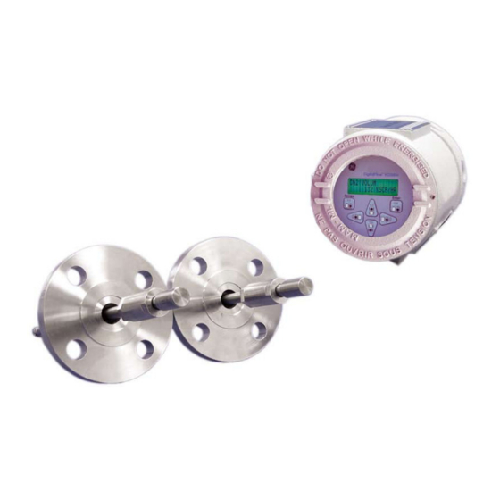
- Page 1 Measurement & Control Gas Analysis DigitalFlow™ XGS868i Panametrics Steam Ultrasonic Mass Flow Transmitter (1 & 2 Channel) Programming Manual 910-196P Rev. G February 2015...
- Page 3 DigitalFlow™ XGS868i Panametrics Steam Ultrasonic Mass Flow Transmitter (1 & 2 Channel) Programming Manual 910-196P Rev. G February 2015 www.ge-mcs.com ©2015 General Electric Company. All rights reserved. Technical content subject to change without notice.
- Page 4 [no content intended for this page]...
- Page 5 Preface Information Paragraphs Note: These paragraphs provide information that provides a deeper understanding of the situation, but is not essential to the proper completion of the instructions. IMPORTANT: These paragraphs provide information emphasizing instructions which are essential to proper setup of the equipment.
- Page 6 Environmental Compliance Waste Electrical and Electronic Equipment (WEEE) Directive GE Measurement & Control is an active participant in Europe’s Waste Electrical and Electronic Equipment (WEEE) take-back initiative, directive 2012/19/EU. The equipment that you bought has required the extraction and use of natural resources for its production. It may contain hazardous substances that could impact health and the environment.
-
Page 7: Table Of Contents
Contents Chapter 1. Programming Site Data 1.1 Introduction ................... .1 1.2 Programming Methods . - Page 8 Contents Chapter 2. Displaying Data 2.1 Introduction...................43 2.2 Displaying Data with the LCD .
- Page 9 Contents Appendix C. Programming the XGS868i Using PanaView™ C.1 Introduction ..................87 C.2 Programming with PanaView™...
- Page 10 Contents viii DigitalFlow™ XGS868i Programming Manual...
-
Page 11: Chapter 1. Programming Site Data
Chapter 1. Programming Site Data Chapter 1. Programming Site Data 1.1 Introduction The Model XGS868i flow transmitter must be properly installed and programmed, as described in the Startup Guide, before it can provide accurate flow rate measurements. After completing the installation and initial setup, use this chapter to program the advanced features of the Model XGS868i’s Keypad Program. -
Page 12: Programming Methods
• interface with multiple GE Measurement & Control instruments. Although the actual displays differ somewhat, the general procedures are the same for all three programming methods. This chapter provides detailed programming instructions for use with the keypad. If you are using PanaView™, see Appendix C, Programming the XGS868i via PanaView™, and/or the PanaView™... -
Page 13: The Xgs868I Enclosure Keypad
Chapter 1. Programming Site Data 1.3 The XGS868i Enclosure Keypad Keypad Program Along with the 2-line, 16-character LCD, the XGS868i includes a 6-key magnetic keypad. The decal cutout for each key contains a hall effect sensor, pushbutton switch and visible red LED. The magnetic wand used to activate a magnetic key is found attached to the meter chassis below the front panel. - Page 14 Chapter 1. Programming Site Data The XGS868i Enclosure Keypad (cont.) When you power up the XGS868i, the display first shows the model and software version: XGS868i Y4AS.STD The meter then starts to display measured parameters. 10.00 Ft/s To enter the Keypad Program, press the [Escape] key, followed by the [Enter] key, and the [Escape] key again. Each successive key must be entered within 10 seconds of the prior key.
-
Page 15: Activating A Channel
Chapter 1. Programming Site Data 1.4 Activating a Channel Channelx-ACTIV submenu permits selection of the desired measurement method. In addition, it is used to activate/deactivate one or both of the channels in a 2-Channel Model XGS868i. While following the programming instructions, refer to Figure 28 on page 77. To access the Channelx-ACTIV submenu: 1. -
Page 16: Entering System Data For The Channel
Chapter 1. Programming Site Data 1.5 Entering System Data for the Channel Channelx-System submenu is used to enter system parameters for the channel. While following the programming instructions, refer to Figure 28 on page 77. 1.5.1 Accessing the Channelx-System Submenu 1. -
Page 17: Selecting Mass Flow Units
Chapter 1. Programming Site Data 1.5.4 Selecting Mass Flow Units 1. Scroll to the desired Mass Flow units for the flow rate display and press [Enter]. The available units for this prompt are determined by the selection made at System Units (see Table 2). Table 2: Available Mass Flow Units English Metric... -
Page 18: Entering Transducer And Pipe Parameters
If you entered the number for a special transducer, proceed to step 3 below. 1.6.1 Special Transducers Note: For special transducers, GE Measurement & Control will supply a transducer data sheet with programming information. 3. Scroll to the transducer Frequency (supplied by the factory) and press [Enter]. -
Page 19: Pipe Data
Chapter 1. Programming Site Data 1.6.2 Pipe Data If either a standard or a special transducer is being used, the programming sequence should be rejoined at this point. 5. To select the appropriate Pipe OD Unit type from the list shown in Table 3 below, scroll to the right side of the screen, and use the up and down arrow keys to step through the list. - Page 20 Chapter 1. Programming Site Data 1.6.2a Path and Axial Lengths (cont.) Note: If a spoolpiece was ordered with the meter, the transducer signal path length and the transducer signal axial length are engraved on the flowcell and/or are included in the documentation supplied with the meter. For on-site transducer installations, refer to Appendix C, Measuring P and L Dimensions, in the Startup Guide.
-
Page 21: Entering Zero Cutoff And Setting Up Inputs
If you selected Temperature, proceed to Temperature Input on the next page. • If you selected Pressure, proceed to Base Temperature on the next page. • IMPORTANT: GE Measurement & Control recommends using a live input for either temperature or pressure when assuming the saturation. DigitalFlow™ XGS868i Programming Manual... -
Page 22: Temperature Input
Chapter 1. Programming Site Data 1.7.4 Temperature Input The Model XGS868 can use either a fixed temperature value or a live temperature input to calculate the steam density for the mass flow rate display. 3. Scroll to a Fixed temperature value or to set up the option card in Slot 1 that will supply the live temperature input and press [Enter]. -
Page 23: Base Pressure
Chapter 1. Programming Site Data 1.7.7 Base Pressure 10. Enter the Base Pressure and press [Enter]. The ratio of this value to the actual pressure is used to calculate the standard mass flow rate. 1.7.8 Low Pressure Switch 11. Scroll to Yes or No to activate or deactivate the Low Pressure Switch software function and press [Enter]. If you selected Yes, enter the Pressure Limit, the low pressure switch set point, and press [Enter]. -
Page 24: Entering Setup Data
Chapter 1. Programming Site Data 1.8 Entering Setup Data Setup The signal limits, response times, mass flow and multiple K factors for the Model XGS868i are specified via the submenu. The following four submenus are included in this section: Signal - set the parameters related to the transducer signal (see below). •... - Page 25 Chapter 1. Programming Site Data 1.8.1 Setting Transducer Signal Parameters (cont.) Table 4: Transducer Signal Settings Transducer Signal Default Parameters Range Value Miscellaneous Information The E1:LOW SIGNAL error message appears when the signal strength falls Signal Low -20 to 100 below the programmed SIGNAL LOW LIMIT value.
-
Page 26: Initializing Setup Parameters - Default Setup
Chapter 1. Programming Site Data Table 4: Transducer Signal Settings (cont.) Transducer Signal Default Parameters Range Value Miscellaneous Information If the burst mode is set to Skan/Measure (S/M), the meter switches from Skan 0 to 250 M>S Switch 50 μsec to Measure Mode when Delta T is less than the M>S_Switch value. -
Page 27: Setting Response Time - V Averaging
IMPORTANT: Do not change this number unless instructed to do so by GE Measurement & Control personnel. 1. In the Keypad Program, scroll to PROG and press [Enter]. 2. In the PROG menu, scroll to CH1 or CH2 and press [Enter]. -
Page 28: Using Advanced Features
Chapter 1. Programming Site Data 1.8.4 Using Advanced Features This option enables you to access the more advanced features of the meter. In this option you can do the following: • enter a table of K factors - to compensate for non-linear flow rates (see below). •... - Page 29 Chapter 1. Programming Site Data 1.8.4c Activating Mass Flow Use this option to calculate mass flow from a static fluid density. Complete the following steps to enter the static density of the fluid: IMPORTANT: The Model XGS868i calculates the actual density from the live or fixed temperature and pressure inputs, Mass flow calculation as programmed in the menu.
-
Page 30: Entering Global Data
Chapter 1. Programming Site Data 1.9 Entering Global Data Global menu is used to enter information that is not specific to either of the individual channels. Information programmed via this menu is used to compute parameters such as the sum, difference or average of the channel 1 and Global channel 2 signals (for a 2-Channel meter). -
Page 31: Entering Global System Data
Chapter 1. Programming Site Data 1.9.1 Entering Global System Data This menu enables you to select the system units that the XGS868i will use when channel data is added, subtracted or averaged together. 1. In the Keypad Program, scroll to PROG and press [Enter]. 2. - Page 32 Chapter 1. Programming Site Data 1.9.1b Selecting Totalizer Units 1. Scroll to the desired Totalizer Units for the totalized flow rate display and press [Enter]. Available units are listed in Table 5 on page 21. 2. Scroll to the desired number of Tot Decimal Digits (digits to the right of the decimal point in the totalized flow rate display) and press [Enter].
-
Page 33: Setting Up Inputs And Outputs
Chapter 1. Programming Site Data 1.9.2 Setting Up Inputs and Outputs Set up the XGS868i’s inputs and outputs via the submenu. While following the programming instructions, refer to Figure 30 on page 79 and Figure 31 on page 80 in Appendix A. The following three submenus are included in this section: •... - Page 34 Chapter 1. Programming Site Data 1.9.2a Selecting Error Handling (cont.) Note: The error responses listed in Table 7 apply only to the Channelx Difference measurement mode and to the Average measurement modes, if either or both channels are in error. Error handling in the measurement mode is set in Step 7 below.
- Page 35 Chapter 1. Programming Site Data 1.9.2b Setting Up Slot 0 and Slot 1 Input/Outputs Slot 0 The Model XGS868i has two built-in analog outputs, which are assigned to . Also, a variety of input/output option Slot 1 cards may be installed in .
- Page 36 Chapter 1. Programming Site Data Setting Up the Output Scale 1. Scroll to the desired output scale and press [Enter]. 2. Do one of the following: If you selected Off, the XGS868i returns to the I/O window. Go to Procedure Options on page 27. •...
- Page 37 Chapter 1. Programming Site Data Table 9: Available Measurement Parameters (cont.) Option Bar Description Good CNTup Displays AGC DAC count for upstream gain setting. N.A. N.A. CNTdn Displays the AGC DAC count for the downstream gain setting. N.A. N.A. P#up Displays signal peaks for the upstream transducer.
- Page 38 Chapter 1. Programming Site Data 1.9.2d Analog Inputs Refer to Figure 31 on page 80, and complete the following steps to set up the analog inputs of an option card installed Slot 1 Accessing the Input 1. In the Keypad Program, scroll to PROG and press [Enter]. 2.
- Page 39 Chapter 1. Programming Site Data 1.9.2e RTD Inputs Option cards with RTD inputs have a temperature range of –148 to 662°F (–100 to 350°C). While following the programming instructions, refer to Figure 31 on page 80, and complete the following steps to set up the RTD inputs of an option card installed in Slot 1.
- Page 40 Chapter 1. Programming Site Data 1.9.2f Alarm Relays Refer to Figure 31 on page 80, and complete the following steps to set up the alarm relays of an option card installed in Slot 1 Accessing the Alarm Relay 1. In the Keypad Program, scroll to PROG and press [Enter]. 2.
- Page 41 Chapter 1. Programming Site Data 1.9.2f Alarm Relays (cont.) Selecting the Alarm Type (cont.) 6. Do one of the following: • high or low - proceed to Step 7 below. • fault - proceed to Step 9 below. 7. Scroll to the desired measurement parameter and press [Enter]. (See Table 9 on page 26 for a description of the available options.) Note: The measurement units that appear in these prompts are those selected in the Global-System...
- Page 42 Chapter 1. Programming Site Data 1.9.2g Totalizer Outputs The totalizer output issues one pulse per selected volume of flow. The meter produces a pulse each time the programmed amount of flow passes through the pipe. Refer to Figure 31 on page 80, and complete the following steps Slot 1 to set up the totalizer outputs of an option card installed in Accessing the Totalizer Output...
- Page 43 Chapter 1. Programming Site Data 1.9.2g Totalizer Outputs (cont.) Setting Up the Totalizer 1. Scroll to the desired Channel option and press [Enter]. 2. Scroll to the desired Measurement parameter and press [Enter]. See Table 10 below for a list of the available options.
- Page 44 Chapter 1. Programming Site Data 1.9.2h Frequency Outputs The frequency output issues a continuous signal with a frequency proportional to the selected measurement. Refer SLOT tFigure 31 on page 80 and complete the following steps to set up the totalizer outputs of an option card installed in Accessing the Frequency Output 1.
- Page 45 Chapter 1. Programming Site Data 1.9.2h Frequency Outputs (cont.) Setting Up the Frequency 1. Scroll to the desired Channel option and press [Enter]. 2. Scroll to the desired Measurement parameter and press [Enter]. See Table 9 on page 26 for a description of the available options.
-
Page 46: Configuring The Communications Port
4. Enter a Meter Address (between 1 and 127) and press [Enter]. (The default address is 1.) A meter address is necessary for communication with the GE Measurement & Control PanaView software. See Appendix C, Programming the XGS868i with PanaView™, or the PanaView™ User’s Manual (910-211) for more information. - Page 47 Chapter 1. Programming Site Data 1.9.3b Setting Up MODBUS Communications When equipped with an optional MODBUS output card, the XGS868i can transmit flow data serially to a flow computer, or SCADA, using a Gould-type RTU protocol. Thus only the MODBUS function command, 3 (read multiple registers), 6 (write multiple registers) is valid.
-
Page 48: Requesting Parameters Using Modbus
Chapter 1. Programming Site Data 1.9.4 Requesting Parameters Using MODBUS To request specific parameters from the XGS868i via the MODBUS, the control system must enter the appropriate register number. Only registers 1 through 90 are available for MODBUS communications, while registers 508 through 512 are used by the XGS868i to store the MODBUS parameters. - Page 49 Chapter 1. Programming Site Data Table 12: MODBUS Registers for a 2-Channel XGS868i MODBUS Scaling Reg # Hex Addr Description (decimal places) Size in Bytes 2 (16 bit signed) 1” Clear Ch1 Totalizers” 2 (16 bit signed) 1“ Clear Ch2 Totalizers” Ch1 Velocity 4 (2 16-bit int) Ch1 Act Volumetric...
- Page 50 Chapter 1. Programming Site Data Table 12: MODBUS Registers for a 2-Channel XGS868i (cont.) MODBUS Scaling Reg # Hex Addr Description (decimal places) Size in Bytes Ch2 Sig Strength Upstream 4 (2 16-bit int) Ch2 Sig Strength Downstream 4 (2 16-bit int) Ch2 Temperature 4 (2 16-bit int) Ch2 Pressure...
-
Page 51: Activating Security
Chapter 1. Programming Site Data 1.9.5 Activating Security In order to prevent unauthorized tampering with the flowmeter’s programming, the XGS868i is equipped with a security feature that locks all the keys except [PROG] (which, when pressed, requires the password). When the system is locked, access to the menus will be denied unless the correct password is entered. The XGS868i is shipped with a default password (2719 and three spaces). - Page 52 Chapter 1. Programming Site Data DigitalFlow™ XGS868i Programming Manual...
-
Page 53: Chapter 2. Displaying Data
Chapter 2. Displaying Data Chapter 2. Displaying Data 2.1 Introduction This chapter explains how to display measurement data using either of the available methods: • LCD Display - show data on the built-in display • PanaView - display data on a computer terminal using the optional PanaView software 2.2 Displaying Data with the LCD When equipped with the Liquid Crystal Display (LCD), the Model XGS868i may be programmed to display up to four variables in sequence. -
Page 54: Programming The Lcd
Chapter 2. Displaying Data 2.2.2 Programming the LCD Note: When you first initialize the XGS868i, the number of LCD parameters is set to OFF. You must program the LCD to display any measured parameters. Through the Keypad Program, you can program the LCD display to display up to four variables in sequence. Complete the following steps to program the LCD display: 1. - Page 55 Chapter 2. Displaying Data 2.2.2 Programming the LCD (cont.) 8. Scroll to the desired Channel option, as listed in Table 13. Table 13: Channel Options Option Description Channel 1 Channel 2 CH1+CH2 CH1-CH2 (CH1+CH2)/2 9. For each channel, select the desired Measurement Parameter, as shown in Table 9 on page 26. Note: The measurement units that appear in these prompts are those selected in the GLOBL-SYSTM menu earlier in this...
-
Page 56: Displaying Data On A Computer Terminal
Chapter 2. Displaying Data 2.3 Displaying Data on a Computer Terminal The flow rate data collected by the XGS868i may be displayed in various formats on a remote computer terminal via the meter’s RS232 serial port. This requires the use of the optional PanaView software. Refer to the instructions below to display data via PanaView. -
Page 57: The Text Display Output
Chapter 2. Displaying Data Displaying Data on a Computer Terminal (cont.) Proceed directly to the appropriate section for instructions on either of the following output options: • Text Display output, discussed below • Graphing output on page 49 Note: For information on the Logging output, see Chapter 3, Logging Data. 2.3.1 The Text Display Output To collect data from the instrument and display it on a text screen, complete the following steps: 1. - Page 58 Chapter 2. Displaying Data 2.3.1 The Text Display Output (cont.) 5. Before actual data values can be displayed in the text pane, activate one of the following data collection modes (see Figure 3 on page 47): • [Get Once] Click on the option button at the bottom of the right pane in the Text Display window.
-
Page 59: The Graphing Output
Chapter 2. Displaying Data 2.3.1b Displaying Multiple Text Windows The procedures for displaying one or more process parameters in a single Text Display window may be repeated to open multiple Text Display windows. To do so, proceed as follows: 1. To open another Text Display window, repeat the steps on page 47 and page 48. 2. - Page 60 Chapter 2. Displaying Data 2.3.2b Graphing Data The PanaView network tree has already been described, and the display pane shows only a graph in the default style with no data points. The bottom right pane enables you to set up the graph. To begin graphing your data, proceed as follows: 1.
-
Page 61: Displaying Transducer Signals
Chapter 2. Displaying Data 2.3.3 Displaying Transducer Signals Along with flow rate data, PanaView enables XGS868i users to read and plot transducer signals from the XGS868i. 1. From the New Meter Browser, highlight the XGS868i. 2. Right-click on the highlighted XGS868i and click on the Properties option, as shown in Figure 5. Figure 5: The Properties Option in the New Meter Browser The Properties window opens, as shown in Figure 6. - Page 62 Chapter 2. Displaying Data 2.3.3a Reading Transducer Signals 3. To read a signal from the meter, click on the [Read Signals] button. (If the meter is a multi-channel instrument, open the Channel drop-down menu and click on the desired channel.) After a moment, the Properties window appears similar to Figure 7.
- Page 63 Chapter 2. Displaying Data 2.3.3c Saving Transducer Signals To save the raw signal, click on [Save]. A window opens similar to Figure 9. Enter the desired name, and click on [Save] to save the signal as a text file. Figure 9: Save As Window DigitalFlow™...
- Page 64 Chapter 2. Displaying Data [no content intended for this page] DigitalFlow™ XGS868i Programming Manual...
-
Page 65: Chapter 3. Logging Data
Chapter 3. Logging Data Chapter 3. Logging Data 3.1 Introduction The XGS868i offers two options for logging data: • Slot 2 If the Model XGS868i flowmeter is equipped with an optional data logging card in , flow rate data can be recorded and stored in this memory in the form of a log file. -
Page 66: Creating Meter Logs
Chapter 3. Logging Data 3.4 Creating Meter Logs To create a new meter log, complete the following steps: 1. From the New Meter Browser in PanaView, expand the network tree and open the Edit Functions option (described in Appendix C, Programming the XGS868i via PanaView). The menu will appear similar to Figure 10. Figure 10: The Edit Functions Menu for an XGS868i with a Logging Card 2. -
Page 67: Creating A Standard Meter Log
Chapter 3. Logging Data 3.4.1 Creating a Standard Meter Log 3. To create a standard meter log, complete the following steps: a. Double-click on the Create Standard Log option.The window now appears similar to Figure 12. Figure 12: Log Location in the Create Standard Log Option b. - Page 68 Chapter 3. Logging Data 3.4.1 Creating a Standard Meter Log (cont.) PanaView indicates a given StartDate. Double-click on OK to agree to the given day, on Today to start the log that day, or on Edit to change the starting date. •...
-
Page 69: Creating An Error Log
Chapter 3. Logging Data 3.4.2 Creating an Error Log To create an error meter log, complete the following steps: 1. Double-click on the Create Error Log option. a. PanaView first asks for the Log Location, either flash or non-volatile RAM. Double-click on the desired location. -
Page 70: Checking Log Memory
Chapter 3. Logging Data 3.4.2 Creating an Error Log (cont.) Note: If you have selected a circular log, PanaView now indicates that the log has been created, and returns to the Log Edit Menu. k. PanaView indicates a given End Time. Double-click on OK to agree to the given time, on Now to start the log immediately, or on Timed to indicate a specific duration. -
Page 71: Creating Pc Logs
Chapter 3. Logging Data 3.5 Creating PC Logs PC logs are created in a different menu from the meter logs described in the last section. To create a new PC log: 1. Open the Output menu (see Figure 13), and click on the Logging option. Figure 13: Selections in the Logging Option You have two choices: •... - Page 72 Chapter 3. Logging Data Creating PC Logs (cont.) Figure 15: Log Type Selection 3. Double click on PC Logs to advance to the dialog box shown in Figure 16. Figure 16: Create a PC Log [Create] 4. At the dialog box shown in Figure 16, click on the option button to create a new meter log.
- Page 73 Chapter 3. Logging Data Creating PC Logs (cont.) 6. At the resulting PC Log window shown in Figure 18, place a check mark in the text box to create a circular log, or leave this box empty to create a linear log. Figure 18: The PC Log Window 7.
-
Page 74: Viewing Meter Log Files
Chapter 3. Logging Data 3.6 Viewing Meter Log Files After one or more meter log files have been created, the logs may be viewed by using the New Meter Browser as follows: 1. From the New Meter Browser in PanaView, expand the network tree and click on the Meter Logs option. If you have created one or more logs, the tree will appear similar to Figure 19. - Page 75 Chapter 3. Logging Data Viewing Meter Log Files (cont.) Note: The graph is displayed in its own window, which is opened on top of the Meter Log window. For instructions on using the Graph Log window, refer to the Graphing Output section in Chapter 2 of the PanaView User’s Manual.
-
Page 76: Viewing Pc Log Files
Chapter 3. Logging Data 3.7 Viewing PC Log Files After one or more PC log files have been created, the logs may be viewed by using PanaView as follows: 1. You can access PC logs in two ways: • From the New Meter Browser in PanaView, expand the network tree and click on the PC Logs option. If you have created one or more logs, the tree will appear similar to Figure 22 below. - Page 77 Chapter 3. Logging Data Viewing PC Log Files (cont.) 2. In the Log Browser, after you highlight the name of the desired log file, the following option buttons become available: • [Start] - resumes logging if the log is currently stopped •...
- Page 78 Chapter 3. Logging Data [no content intended for this page] DigitalFlow™ XGS868i Programming Manual...
-
Page 79: Chapter 4. Printing Data
Chapter 4. Printing Data Chapter 4. Printing Data 4.1 Data Types for Printing The Model XGS868i flowmeter has no ability to print any of its data directly. However, any of the data stored in its memory may be printed via the built-in RS232 communications port, using a computer terminal. In order to use the capability, the XGS868i must be linked to the computer terminal with the optional PanaView software. - Page 80 Chapter 4. Printing Data [no content intended for this page] DigitalFlow™ XGS868i Programming Manual...
-
Page 81: Chapter 5. Clearing Data
Chapter 5. Clearing Data Chapter 5. Clearing Data 5.1 Introduction This chapter explains how to purge totalized measurements, site data and/or log files from the XGS868i’s memory. Note: For detailed information on creating a log file, see Chapter 3, Logging Data. For detailed information on programming site data, see Chapter 1, Programming Site Data. -
Page 82: Clearing Log Files
Chapter 5. Clearing Data 5.2.2 Clearing Log Files To clear log files from the XGS868i or from the PC’s memory, complete the following steps: 1. From PanaView, click on the Logging option in the Output menu. Then click on the Log Browser option, as shown in Figure 24. -
Page 83: Clearing The Totalizers
Chapter 5. Clearing Data 5.2.3 Clearing the Totalizers You can clear the XGS868i’s totalizers (i.e., reset specified totalized flow rates to zero) from either the LCD display (see Appendix A) or from PanaView (see Appendix D). To reset totals from the display, complete the following steps: 1. - Page 84 Chapter 5. Clearing Data [no content intended for this page] DigitalFlow™ XGS868i Programming Manual...
-
Page 85: Appendix A. Menu Maps
Appendix A. Menu Maps Appendix A. Menu Maps DigitalFlow™ XGS868i Programming Manual... - Page 86 [no content intended for this page] DigitalFlow™ XGS868i Programming Manual...
- Page 87 Appendix A. Menu Maps [Esc] [Enter] [Esc] Keypad Pgm. PROG RESET CALIB CNTRS Reset Totals (* for 2-Channel meter only) See Service Manual DARKN LITEN CH2* GLOBL STORE ABORT SYSTM COMM SECUR See Figure 30 ACTIV SYSTM PIPE SET UP CHANNEL LABEL TRANSDUCER NUMBER ZERO CUTOFF...
- Page 88 Appendix A. Menu Maps [Esc] [Enter] [Esc] Keypad Program PROG RESET CALIB CNTRS Reset Totals (* for 2-Channel meter only) See Service Manual DARKN LITEN CH2* GLOBL STORE ABORT SECUR SYSTM COMM See Figure 30 See Figure 30 System Pipe Parameters Input/Output Status SET UP...
- Page 89 Appendix A. Menu Maps [Esc] [Enter] [Esc] Keypad Pgm. PROG RESET CALIB CNTRS Reset Totals (* for 2-Channel meter only) See Service Manual DARKN LITEN CH2* GLOBL See Figures 28 and 29 STORE ABORT SECUR SYSTM COMM METER MESSAGE Meter Address SYSTEM UNITS BAUD RATE ERROR...
- Page 90 Appendix A. Menu Maps [Esc] [Enter] [Esc] Keypad Pgm. PROG RESET CALIB CNTRS Reset Totals (* for 2-Channel meter only) See Service Manual DARKN LITEN CH2* GLOBL See Figures 28 and 29 STORE ABORT SYSTM COMM SECUR See Figure 30 See Figure 30 See Figure 30 Error Handling...
-
Page 91: Appendix B. Data Records
Appendix B. Data Records Appendix B. Data Records B.1 Available Option Cards and one in Slot 2. The available configurations are listed in Slot 1 The Model XGS868i can hold one option card in Table 14. Table 14: Option Card Configurations Card # Slot # Configuration... -
Page 92: Option Cards Installed
Appendix B. Data Records B.2 Option Cards Installed Whenever an option card is installed or changed in the Model XGS868i flow transmitter, record the type of card and any additional setup information in the appropriate row of Table 15. Table 15: Option Cards Installed Slot # Type of Option Card Additional Setup Information... -
Page 93: Setup Data
Appendix B. Data Records B.3 Setup Data After the Model XGS86i flow transmitter has been installed, setup data must be entered via the User Program prior to operation. Record that information in Table 16. Table 16: Setup Data General Information Model # Serial # Software Vers. - Page 94 Appendix B. Data Records Table 16: Setup Data (cont.) Channel - Pipe Parameters Channel 1 Channel 2 Trans. Type SPEC Trans. Type SPEC Transducer # Transducer # Spec. Trans. Hz Spec. Trans. Hz Spec. Trans. Tw Spec. Trans. Tw Pipe O.D. Pipe O.D.
- Page 95 Appendix B. Data Records Table 16: Setup Data (cont.) Channel - SETUP - Advanced Features - Multi K Factors (cont.) K-Factor # Velocity K-Factor K Factor # Velocity K-Factor DigitalFlow™ XGS868i Programming Manual...
- Page 96 [no content intended for this page] DigitalFlow™ XGS868i Programming Manual...
-
Page 97: Appendix C. Programming The Xgs868I Using Panaview
Appendix C. Programming the XGS868i Using PanaView™ Appendix C. Programming the XGS868i Using PanaView™ C.1 Introduction The Model XGS868i flow transmitter must be properly installed and programmed, as described in the Startup Guide, before it can provide accurate flow rate measurements. After completing the installation and initial setup, use this chapter to program the advanced features of the Model XGS868i’s via the PanaView™... -
Page 98: Setting Up The Communications Port
Appendix C. Programming the XGS868i Using PanaView™ C.2.2 Setting Up the Communications Port Use the steps below to establish PanaView communications with the XGS868i. 1. Launch PanaView, as discussed in Chapter 3, Initial Setup, of the PanaView User’s Manual. 2. Open the New Meter Browser window in the File menu and expand the network tree. Then, highlight the My Computer (Name) branch by clicking on it. - Page 99 Appendix C. Programming the XGS868i Using PanaView™ C.2.2 Setting Up the Communications Port (cont.) 5. Click on the Communications Port option to select it. The Setup Communications screen appears similar to Figure 33. Figure 33: Setup Communications Screen 6. Open the Protocol menu (the first of the drop-down menus) and click on IDM. 7.
-
Page 100: Setting Up Ethernet Communications
Appendix C. Programming the XGS868i Using PanaView™ C.2.3 Setting up Ethernet Communications If you have selected TCP/IP in step 6 on the previous page, the Setup Communications window appears similar to Figure 34. Figure 34: Setup Communications for TCP/IP 1. Type in the desired Name and Timeout (in milliseconds). Device Discovery 2. -
Page 101: Modifying Ethernet Parameters
Appendix C. Programming the XGS868i Using PanaView™ C.2.4 Modifying Ethernet Parameters To establish Ethernet communications with the XGS868i or to modify its IP parameters, you will need to install the Ethernet Device Discovery software utility (available with your XGS868i) on a PC connected to the LAN. Once installed and running, the software displays all Ethernet devices currently connected to the subnet. -
Page 102: Adding The Xgs868I
Appendix C. Programming the XGS868i Using PanaView™ C.3 Adding the XGS868i To add the XGS868i on the IDM-configured communications port, complete the following steps: 1. Highlight the communication port to which the meter will be added by clicking on it, and then open the Edit menu on the menu bar (if the communication port is not highlighted first, the New Meter option is not active in the Edit menu). - Page 103 Appendix C. Programming the XGS868i Using PanaView™ Adding the XGS868i (cont.) IMPORTANT: The Network ID number must match the Network ID programmed in the meter’s Communications menu. If the initialization is successful, the Meter Browser shows a listing similar to Figure 37. Figure 37: The Updated Network Tree However, if the settings do not match, or there is some other difficulty, a screen appears similar to Figure 38.
-
Page 104: Entering The User Program Using Panaview
Appendix C. Programming the XGS868i Using PanaView™ C.4 Entering the User Program using PanaView Note: Be sure to record all the programming data entered in this chapter in Appendix B, Data Records. Status System Pipe Channel Global-System Programming of the , and submenus of the menu and the... - Page 105 Appendix C. Programming the XGS868i Using PanaView™ Entering the User Program using PanaView (cont.) Figure 40: Menus in the Edit Functions Option 3. To enter data into the user program, double-click on the Site Edit Menu. The window appears similar to Figure 41. Note: For a 1-Channel XGS868i, the Channel 2 option does not appear.
- Page 106 Appendix C. Programming the XGS868i Using PanaView™ Entering the User Program using PanaView (cont.) Figure 42: Pipe Parameters Option in the Site Edit Menu c. Do one of the following: Click on [ Next Item] to proceed to the next menu item, or Click on [ ] to return back through the menu to a previous item.
-
Page 107: Entering Data In The Channel Menu
Appendix C. Programming the XGS868i Using PanaView™ C.5 Entering Data in the Channel Menu Channel menu is used to enter data specific to each channel. Refer to Figure 52 on page 139 and Figure 53 on page 140 in Appendix D, PanaView Menu Maps, and remember to record all programming data in Appendix B, Data Records. -
Page 108: Entering Data In The Channel System Option
Appendix C. Programming the XGS868i Using PanaView™ C.5.2 Entering Data in the Channel System Option 1. From the Channel PROGRAM menu, highlight and double-click on the System option in the center pane. 2. The first prompt asks for the Channel (Site) Label. Enter the desired label (in any numeric or text combination up to five characters) in the right pane, and click [Next Item]. - Page 109 Appendix C. Programming the XGS868i Using PanaView™ C.5.2a Programming the Mass Flow Option 1. Double-click on the desired Mass Flow units for flow rate display (listed in Table 18). Table 18: Available Mass Flow Units English Metric Pounds Kilograms KiloPounds = Thousands of Tonnes = Metric Tons (1000 KG) Pounds MillionPounds...
-
Page 110: Entering Pipe Parameters
3. For special transducers: Note: GE Measurement & Control will supply the information required for steps a and b with the transducers. a. Double-click on the appropriate Frequency (from 25 kHz to 500 kHz).The frequency is required to transmit an excitation voltage at the transducer’s natural frequency. - Page 111 Appendix C. Programming the XGS868i Using PanaView™ C.5.3b Pipe OD 4. Click on the appropriate Pipe OD Unit type in the center pane from the list shown in Table 19. Then enter the known pipe outside diameter or circumference in the right pane and click [Next Item]. Obtain the required information by measuring either the pipe outside diameter (OD) or circumference at the transducer installation site.
-
Page 112: Entering Input/Output Parameters
If you selected Temperature, proceed to Temperature Input on page 103. • If you selected Pressure, proceed to Base Temperature on page 103. • Note: GE Measurement & Control recommends using a live input for either temperature or pressure when assuming the saturation. DigitalFlow™ XGS868i Programming Manual... - Page 113 Appendix C. Programming the XGS868i Using PanaView™ C.5.4d Temperature Input The XGS868i can use either a fixed temperature value or a live temperature input to calculate the density for the mass flow rate display. 1. Double-click on a Fixed temperature value or to set up the option card in Slot 1 that will supply the live temperature input and click [Next Item].
- Page 114 Appendix C. Programming the XGS868i Using PanaView™ C.5.4f Pressure Input 1. Double-click on a Fixed pressure value or to set up the option card in Slot 1 that will supply the live pressure input. Note: If Slot 1 contains an activated option card with an input assigned to Pressure, Slot 1 appears as an option at the above prompt.
- Page 115 Appendix C. Programming the XGS868i Using PanaView™ C.5.4i Quality Input Quality Input When the temperature and pressure inputs indicate that the steam is saturated, the value is used for the mass flow rate calculations. Unless a different value is accurately known, accept the default value at the following prompt: Note: The quality value indicates what fraction of the fluid is in the gas phase.
-
Page 116: Entering Setup Parameters
Appendix C. Programming the XGS868i Using PanaView™ C.5.5 Entering Setup Parameters SETUP The signal limits and response times for the Model XGS868i are specified via the submenu. While following the programming instructions, refer to Figure 53 on page 140 of Appendix D, PanaView Menu Maps. This submenu includes four options: •... - Page 117 Appendix C. Programming the XGS868i Using PanaView™ Table 20: Transducer Signal Settings Transducer Signal Default Parameters Range Value Description The E1:LOW SIGNAL error message appears when the signal strength Signal Low 20 to 100 falls below the programmed SIGNAL LOW LIMIT value. See Chapter 2 in Limit Service Manual for a discussion of error codes.
- Page 118 Appendix C. Programming the XGS868i Using PanaView™ Table 20: Transducer Signal Settings (cont.) Transducer Signal Default Parameters Range Value Description If the burst mode is set to Skan/Measure (S/M), the meter switches from M>S Switch 0 to 250 μsec 50 μsec Skan to Measure Mode when Delta T is less than the M>S_Switch value.
- Page 119 Appendix C. Programming the XGS868i Using PanaView™ C.5.5d The Advanced Features Option This option enables you to enable the more advanced features of the meter. In this option you can do the following: • enter a table of K-factors (based on velocity or reynolds number) that compensates for non-linear flow rates •...
-
Page 120: Entering Data In The Global Menu
Appendix C. Programming the XGS868i Using PanaView™ The Mass Flow Option Use this option to calculate mass flow from a static fluid density. Complete the following steps to enter the static density of the fluid: 1. From the Advanced Features option menu, highlight and double-click on Mass flow calculation in the center pane. 2. -
Page 121: Entering Global-System Data
Appendix C. Programming the XGS868i Using PanaView™ C.6.1 Entering Global-System Data While completing these instructions, see the menu map in Figure 54 on page 141 in Appendix D, PanaView Menu Maps. 1. In the Site Data Menu, double-click on the Global entry. 2. - Page 122 Appendix C. Programming the XGS868i Using PanaView™ C.6.1a Volumetric Units 1. Double-click on the desired Volumetric Units for the flow rate display. Table 21 lists the available units. Table 21: Available Volumetric/Totalizer Units English Metric Actual Cubic Feet Actual Cubic Meters Thousands of ACF Thousands of ACM Millions of ACF...
-
Page 123: Setting Up Inputs And Outputs
Appendix C. Programming the XGS868i Using PanaView™ C.6.1c Selecting Mass Flow Units 1. Double-click on the desired Mass Flow units for flow rate display (listed in Table 22). Table 22: Available Mass Flow Units English Metric Pounds Kilograms KiloPounds Tonne = Metric Tons (1000 KG) (Thousands of Pounds) MillionPounds TONS (2000 LB) - Page 124 Appendix C. Programming the XGS868i Using PanaView™ C.6.2a Setting Up Error Handling This menu option lets you set how the XGS868i will handle the outputs for measurements and average (two-path) measurements during an error condition. See Chapter 2, Error Codes, in the Service Manual for a discussion of the built-in error codes.
- Page 125 Appendix C. Programming the XGS868i Using PanaView™ Error Handling for Average Measurements - AVE 2PATH ERROR HANDLING option is intended for applications where two sets of transducers are installed in the same location in the same pipe to improve accuracy and the meter is operated in mode.
- Page 126 Appendix C. Programming the XGS868i Using PanaView™ C.6.2b Setting Up Option Cards Slot 0 The Model XGS868i has two built-in analog outputs, which are assigned to . Also, a variety of input/output option Slot 1 cards may be installed in .
- Page 127 Appendix C. Programming the XGS868i Using PanaView™ Analog Outputs (cont.) Note: All the options shown below will only appear if Mass Flow is activated. Table 27: Available Measurement Parameters Option Bar Description Good Velocity Displays the flow velocity. N.A. N.A. Volumetric Displays the volumetric flow.
- Page 128 Appendix C. Programming the XGS868i Using PanaView™ Table 27: Available Measurement Parameters (cont.) Option Bar Description Good Displays Skan Delta T. N.A. N.A. DeltaT S Displays Measure transit time upstream. N.A. N.A. UP Transit M Displays Measure transit time downstream. N.A.
- Page 129 Appendix C. Programming the XGS868i Using PanaView™ Option Card Analog Inputs Slot 1 Complete the following steps to set up the analog inputs of an option card installed in (refer to Figure 55 on page 142): 1. Double-click on the desired Input (A, B, C or D). Note: The setup of input A is used as an example.
- Page 130 Appendix C. Programming the XGS868i Using PanaView™ Option Card RTD Inputs Option cards with RTD inputs have a temperature range of –148 to 660 F (–100° to 350°C). Complete the following steps to set up the RTD inputs of an option card installed in Slot 1 (refer to Figure 55 on page 142): 1.
- Page 131 Appendix C. Programming the XGS868i Using PanaView™ Option Card Alarm Relays Slot 1 Complete the following steps to set up the alarm relays of an option card installed in (refer to Figure 55 on page 142): 1. Double-click on the desired Output (A, B, C or D). Note: The set up of alarm A is used here as an example.
- Page 132 Appendix C. Programming the XGS868i Using PanaView™ Option Card Totalizer Outputs This type of output issues one pulse per selected volume of flow. The meter produces a pulse each time the programmed amount of flow passes through the pipe. Complete the following steps to set up the totalizer outputs of an Slot 1 option card installed in 1.
- Page 133 Appendix C. Programming the XGS868i Using PanaView™ Option Card Frequency Outputs This type of output produces a frequency pulse that is proportional to the output measurement. Complete the following Slot 1 steps to set up the frequency outputs of an option card installed in (see Figure 55 on page 142): 1.
- Page 134 Appendix C. Programming the XGS868i Using PanaView™ C.6.2c Programming the LCD Through PanaView, you can program the LCD display to display up to four variables in sequence. Complete the following steps to program the LCD display: Note: When you first initialize the XGS868i, the number of LCD parameters is set to OFF. You must program the LCD to display any measured parameters.
-
Page 135: Entering Communications Data
2. Enter a Meter Address number between 1 and 254 and click [Next Item]. The default number is 1. A meter address is only necessary for communication with the GE Measurement & Control PanaView software. See the PanaView User’s Manual for more information. - Page 136 Appendix C. Programming the XGS868i Using PanaView™ C.6.3b Requesting Parameters Using MODBUS To request specific parameters from the XGS868i via the MODBUS, the control system must access the appropriate register number, as shown in Table 31. Only registers 1–84 are available with the XGS868i for MODBUS communications.
- Page 137 Appendix C. Programming the XGS868i Using PanaView™ Table 31: MODBUS Registers (cont.) MODBUS DPR Hex Scaling Reg # Addr Description Units (decimal places) Size in Bytes TOT_U Register 46 4 (32 bit integer) AVG-Totals AVG #T Digits none 2 (16 bit integer) 4 (32 bit integer) AVG Totalizer Time none...
- Page 138 Appendix C. Programming the XGS868i Using PanaView™ C.6.3b Requesting Parameters Using MODBUS (cont.) Notes: 1. Clear Totalizers: flag from the 8051 to clear totalizers in the 68332 memory. 2. Error Value: see table in XGS868i manual for error codes 3. Average: average of channel 1 and channel 2 if both channels out of error, channel 1 value if channel 2 is in error, channel 2 value if channel 1 is in error,...
- Page 139 Appendix C. Programming the XGS868i Using PanaView™ C.6.3b Requesting Parameters Using MODBUS (cont.) Notes: 1. Clear Totalizers: flag from the 8051 to clear totalizers in the 68332 memory. 2. Error Value: see table in XMT868i manual for error codes 3. Average: average of channel 1 and channel 2 if both channels out of error, channel 1 value if channel 2 is in error, channel 2 value if channel 1 is in error,...
- Page 140 Appendix C. Programming the XGS868i Using PanaView™ C.6.3c Activating Security in the Global Menu In order to prevent unauthorized tampering with the flowmeter’s programming, the XGS868i is equipped with a security feature that locks all the keys except [PROG] (which, when pressed, requires the password). When the system is locked, access to the menus will be denied unless the correct password is entered.
-
Page 141: Exiting The Site Edit Menu
Appendix C. Programming the XGS868i Using PanaView™ C.6.3c Activating Security in the Global Menu (cont.) [Next Item] 3. Enter the current or default Password and click Figure 48: Entering Password UNlck PROGRAM LOCK 4. At the Lock Out prompt, click to unlock the system and return to the initial menu, or click lock the system. -
Page 142: Saving Site Data
Appendix C. Programming the XGS868i Using PanaView™ C.8 Saving Site Data The XGS868i holds setup parameters for a single internal site, called Working. Through PanaView, users can store site file data in a PC and reload it into the XGS868i. To save or reload site data via PanaView: 1. -
Page 143: Saving Current Site Data To The Meter
Appendix C. Programming the XGS868i Using PanaView™ Saving Site Data (cont.) 3. Click on the [Site Files] button. The Site File Operations window (shown in Figure 51) opens. Figure 51: The Site File Operations Window C.8.1 Saving Current Site Data to the Meter To save existing site data to the meter: 1. -
Page 144: Saving New Site Data To The Xgs868I
Appendix C. Programming the XGS868i Using PanaView™ C.8.2 Saving New Site Data to the XGS868i To save new site data to the meter: 1. Select the radio button for New and click on the [Save Site to Meter] button. 2. A window opens similar to Figure 53. Enter the desired name, and click [OK]. Figure 53: Site Name Entry Window 3. -
Page 145: Clearing A Site From The Meter
Appendix C. Programming the XGS868i Using PanaView™ C.8.4 Clearing a Site from the Meter As the XGS868i has only one site (Working) at any time, it is not possible to remove this site. To change site parameters, first save a site to the PC (as discussed in Saving a Site to the PC on page 134), and then save the site to the XGS868i (as discussed in Saving New Site Data to the XGS868i on page 134). - Page 146 Appendix C. Programming the XGS868i Using PanaView™ DigitalFlow™ XGS868i Programming Manual...
-
Page 147: Appendix D. Panaview Menu Maps For The Xgs868I
Appendix D. PanaView Menu Maps for the XGS868i Appendix D. PanaView Menu Maps for the XGS868i DigitalFlow™ XGS868i Programming Manual... - Page 148 [no content intended for this page] DigitalFlow™ XGS868i Programming Manual...
- Page 149 Appendix D. PanaView Menu Maps FILE New Meter Browser XGS868I Edit Functions SITE EDIT MENU CALIBRATION/TEST PAUSE MEASUREMENT See Service Manual PAUSE: Measure Flow Channel 1 Channel 2* Global MEASURE FLOW STOP MEASUREMENT System Input/Output Comm Port Security See Figure 54 See Figure 55 See Figure 54 See Figure 54...
- Page 150 Appendix D. PanaView Menu Maps FILE New Meter Browser XGS868I Edit Functions SITE EDIT MENU CALIBRATION/TEST PAUSE MEASUREMENT See Service Manual PAUSE: Measure Flow Channel 1 Channel 2* Global MEASURE FLOW STOP MEASUREMENT System Input/Output Comm Port Security See Figure 54 See Figure 55 See Figure 54 See Figure 54...
- Page 151 Appendix D. PanaView Menu Maps FILE New Meter Browser XGS868I Edit Functions SITE EDIT MENU CALIBRATION/TEST PAUSE MEASUREMENT See Service Manual PAUSE: Measure Flow Channel 1 Channel 2* Global MEASURE FLOW STOP MEASUREMENT System Input/Output Security Comm Port METER MESSAGE Meter Address SYSTEM UNITS BAUD RATE...
- Page 152 Appendix D. PanaView Menu Maps FILE New Meter Browser XGS868I Edit Functions SITE EDIT MENU CALIBRATION/TEST PAUSE MEASUREMENT See Service Manual PAUSE: Measure Flow Channel 1 Channel 2* Global MEASURE FLOW STOP MEASUREMENT See Figures 52 and 53 System Input/Output Comm Port Security See Figure 54...
-
Page 153: Appendix E. Foundation Fieldbus Communications
Appendix E. Foundation Fieldbus Communications Appendix E. Foundation Fieldbus Communications E.1 Introduction Foundation Fieldbus provides a means of communicating with the flowmeter. The patent numbers which apply are 5,909,363 and 6,424,872. This Foundation Fieldbus device supports 6 Analog Input (AI) blocks, which can be configured to supply the following measurements on the network (see Table 32). -
Page 154: Configuration Utility Setup
Appendix E. Foundation Fieldbus Communications E.2 Configuration Utility Setup The following is an example setup using National Instruments Configuration Utility v3.1. Figure 56 shows the Configuration Utility with a flowmeter on the network (GE Flow-XGM). Figure 56: Configuration Utility Setup Example Note: The following procedures assume that the device has been placed in the OOS (out-of-service) mode before executing. - Page 155 Appendix E. Foundation Fieldbus Communications Selecting the Desired Measurements (cont.) 4. After the desired measurements have been selected for the PRIMARY and SECONDARY SELECTOR, choose the unit system (UNIT_SELECTOR above the PRIMARY_SELECTOR) that has been programmed in the flowmeter (English or SI).
-
Page 156: Selecting Units For Ai Blocks
Appendix E. Foundation Fieldbus Communications E.4 Selecting Units for AI Blocks To select the units for the individual AI blocks: 1. Double click on the AI block for which you wish to set the units (ANALOG_INPUT_1 or ANALOG_INPUT_2 in the tree under GEFlow-XGM;... -
Page 157: Resetting Instrument Totalizers
Appendix E. Foundation Fieldbus Communications E.5 Resetting Instrument Totalizers To reset the instrument totalizers: 1. Double click on the FLOW transducer block (in the tree under GEFlow-XGM; see Figure 56 on page 144). 2. Select the Others tab and scroll down to the CLEAR_TOTALIZERS listing. 3. -
Page 158: Function Block Application
Appendix E. Foundation Fieldbus Communications E.6 Function Block Application Figure 60 is an example setup using the Function Block Application editor. The flowmeter AI blocks, along with the AO and PID of another device on the network, are displayed. We have connected the AI_1 OUT of the flowmeter to the CAS IN of the AO block. -
Page 159: Appendix F. Foundation Fieldbus Tables
Appendix F. Foundation Fieldbus Tables Appendix F. Foundation Fieldbus Tables Table 33: GE Fieldbus Device Capability, XGX868 Family of Meter Types GF868, GS868, GM868, XGF868i, XGM868i, and Model XGS868i 1 --General Is the Device registered at the Fieldbus Foundation (Yes/No) - Page 160 Appendix F. Foundation Fieldbus Tables Table 33: GE Fieldbus Device Capability, XGX868 Family of Meter Types (cont.) 1.17 Meter Software version (minimum and higher) GF868: GF3S; GM868:GM3Q; GS868: GS3N; GC868: GC4C; XGM868i: Y4DM; XGS868: Y4DS; XGF868i:Y4DF 1.18 Firmware on FF card version 868_GAS_FF_206 1.19...
- Page 161 Appendix F. Foundation Fieldbus Tables Table 33: GE Fieldbus Device Capability, XGX868 Family of Meter Types (cont.) 5 - User Layer General Function Block Application Manufacturer Fieldbus Inc. Function Blocks (list all type, but not including 6 - AI(e), 1 - PID(e), 2 -TB(c), 1 - RB2(e)
- Page 162 Appendix F. Foundation Fieldbus Tables Table 33: GE Fieldbus Device Capability, XGX868 Family of Meter Types (cont.) List by Channel, Unit Code, Enumerated description, and Function Block Type (if Channels XD_SCALE and CHANNEL value applicable) Channel 0 Channel 1 Channel 1 - "Primary Value"/"Secondary Value"...
- Page 163 Appendix F. Foundation Fieldbus Tables Table 33: GE Fieldbus Device Capability, XGX868 Family of Meter Types (cont.) 33026 - thousands of standard cubic meters (changed to 34043) 33037 - millions of actual cubic feet (changed to 34004) 33042 - millions of actual cubic meters (...
- Page 164 Appendix F. Foundation Fieldbus Tables Table 33: GE Fieldbus Device Capability, XGX868 Family of Meter Types (cont.) 1357 - cubic feet per minute 1358 - cubic feet per hour 1359 - cubic feet per day 1497 - cubic kilometer per second...
- Page 165 Appendix F. Foundation Fieldbus Tables Table 33: GE Fieldbus Device Capability, XGX868 Family of Meter Types (cont.) 34018 - Millions of Standard cubic feet per second 34019 - Millions of Standard cubic meter per 34020 - Millions of Standard cubic meter per...
- Page 166 Appendix F. Foundation Fieldbus Tables Table 33: GE Fieldbus Device Capability, XGX868 Family of Meter Types (cont.) 34045 - Thousands of Standard cubic meters per hour 34046 - Thousands of Standard cubic meters per minute 34047 - Thousands of Standard cubic meters...
- Page 167 Index Symbols ....... . . 26 Calibration Factor +MASS ......101 in PanaView .
- Page 168 Index Diagnostics ..... 100 Frequency, in PanaView ....15 Acceleration Limit .
- Page 169 Index Input/Output Menu ........26 -MASS ....11 Assume Saturation .
- Page 170 Index Option Card Setup Pressure Input ......30 ....... 12 Alarm Relays Entering .
- Page 171 Index Setup Data Startup ......18 ....94 Advanced Features See Basic Programming .
- Page 172 Index ....10 ......117 Tracking Windows, Activating Volumetric .
- Page 173 AUTHORIZATION NUMBER (RAN), and shipping instructions for the return of the instrument to a service center will be provided. 2. If GE Sensing instructs you to send your instrument to a service center, it must be shipped prepaid to the authorized repair station indicated in the shipping instructions.
- Page 174 Warranty [no content intended for this page] DigitalFlow™ XGS868i Programming Manual...
- Page 176 Customer Support Centers U.S.A. The Boston Center 1100 Technology Park Drive Billerica, MA 01821 U.S.A. Tel: 800 833 9438 (toll-free) 978 437 1000 E-mail: [email protected] Ireland Sensing House Shannon Free Zone East Shannon, County Clare Ireland Tel: +353 (0)61 470200 E-mail: [email protected] An ISO 9001:2008 Certified Company www.ge-mcs.com/en/about_us/quality.html...