Table of Contents
Quick Links
Table of Contents

Related Manuals for GE DewPro MMY30


Summary of Contents for GE DewPro MMY30
- Page 1 Sensing DewPro® MMY30 General Eastern Trace Moisture Transmitter User’s Manual...
- Page 2 Sensing ® DewPro MMY30 General Eastern Trace Moisture Transmitter User’s Manual A40251540A November 2005 ® DewPro is a GE General Eastern product. GE General Eastern has joined other GE high-technology sensing businesses under a new name—GE Sensing.
- Page 3 If a GE Infrastructure Sensing, Inc. instrument malfunctions within the warranty period, the following procedure must be completed: 1. Notify GE Infrastructure Sensing, Inc., giving full details of the problem, and provide the model number and serial number of the instrument.
-
Page 4: Table Of Contents
November 2005 Table of Contents Chapter 1: General System Information Unpacking and Inspection ............. . 1-1 Product Structure. - Page 5 Description of the DewPro MMY30 Programming Matrix........
- Page 6 Chapter 1...
- Page 7 General System Information Unpacking and Inspection ........1-1 Introduction.
-
Page 8: Chapter 1: General System Information
November 2005 Unpacking and Upon receipt of the DewPro MMY30, examine the shipping carton Inspection for broken or open packing, distortion, or any other evidence of mishandling. If inspection indicates damage to the unit or any of its components, notify the carrier (within 15 days of delivery) and request an inspection. - Page 9 November 2005 Product Structure (cont.) Orifice Configuration: A Inlet: None; Outlet: Orifice, with ¼” FNPT B Inlet: None; Outlet: Orifice, with (6 mm) ¼” tube fitting C Inlet: None; Outlet: None, with (6 mm) ¼” tube fitting D Inlet: Orifice; Outlet: None, with (6 mm) ¼” tube fitting S Other Enclosure Conduit: 1 M20 X 1.5 F with cable gland...
-
Page 10: Introduction
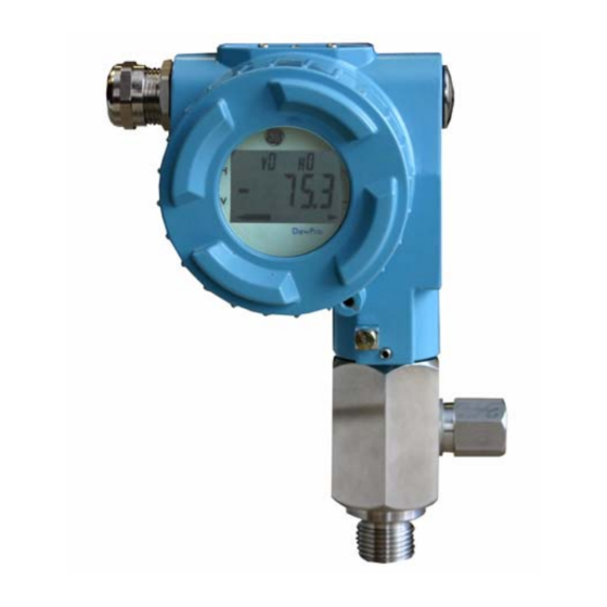
November 2005 Introduction Unit Description The DewPro MMY30 trace moisture transmitter (shown in Figure 1-2 below) is a loop-powered dewpoint measuring device. The transmitter includes a sensor element, a flow chamber, a weather- proof enclosure, microprocessor electronics, and assorted fittings, all in a compact assembly. -
Page 11: Theory Of Operation
Each DewPro is factory calibrated against precise NIST certified moisture references and has an accuracy of ±2°C dewpoint at 25°C temperature. For field validation, GE Sensing offers a unique validation device. The MMY245 field validator connects to the DewPro on site and offers a one-point or two-point correction. -
Page 12: Dimensions
November 2005 Dimensions Choose a mounting location which allows enough clearance for the use of tools and for connection of the field validator. Figure 1-3 shows the dimensions of the standard DewPro, and Figure 1-4 shows the DewPro with the optional display/user interface. Figure 1-3: Standard DewPro Dimensions Figure 1-4: Dimensions for DewPro with Optional Display/ User Interface... - Page 13 Chapter 2...
-
Page 14: Installation Guidelines
Installation Guidelines General Hints ........... 2-1 Method I - Orifice at Outlet . -
Page 15: Chapter 2: Installation Guidelines
November 2005 General Hints Caution! Before installation, please read all instructions. The DewPro is designed to be mounted to pressurized systems. Take all necessary precautions when mounting or removing the DewPro. • Mount the DewPro vertically whenever possible to prevent particles or condensation from entering the bypass. -
Page 16: Method I - Orifice At Outlet
November 2005 Method I - Orifice at Figure 2-1 below illustrates installation at the orifice at the outlet. Outlet Figure 2-1: DewPro Installation at Orifice at Outlet Pressure Dewpoint Air dryers producing general instrument air are typically specified with a pressure dewpoint rating. The majority of dryers operate in a dewpoint range between -40°C and -75°C (-40°F and -100°F). -
Page 17: Method Ii - Orifice At Inlet
November 2005 Method II - Orifice at Figure 2-2 below shows installation at the orifice at the inlet. Inlet Figure 2-2: DewPro Installation at Orifice at Inlet Method III - No Flow Figure 2-3 below illustrates an installation with no flow restrictions. Restriction Figure 2-3: DewPro Installation with No Flow Restriction Low Pressure Closed Loop... -
Page 18: Method Iv - Bypass Installation
November 2005 Method IV - Bypass Installation Figure 2-4: Remote Wall Mount Bypass Remote Installation In some cases there may not be enough room to install the DewPro directly to the process pipe. The tube connection at the inlet allows mounting the DewPro at a remote location. - Page 19 Chapter 3...
- Page 20 Wiring Instructions General Guidelines ..........3-1 System Configuration .
-
Page 21: Chapter 3: Wiring Instructions
System Configuration Various Power Supplies Figure 3-1 below illustrates various power supplies and displays for use with the DewPro MMY30. Figure 3-1: Power Supplies/Displays for MMY30 Designing the Loop When selecting a power supply, please note that the voltage at the +/- terminal of the DewPro should not fall below 12 VDC. -
Page 22: Mounting In Normal Environments
Environments with Severe Electrical Noise EMI/RFI The DewPro MMY30 meets the EMC requirements of IEC 61326 for equipment used in industrial locations. The MMY30 passed all tests to the standards IEC 61000-4- to the performance criterion A. Test details can be found in Chapter 6, Specifications. -
Page 23: Electrical Connection
November 2005 Electrical Connection Figure 3-4 below illustrates electrical connections for the DewPro MMY30. Figure 3-4: Electrical Connections General Instructions 1. Unscrew the cap on the terminal side of the unit. 2. Loosen the cable gland located on the side of the unit. 3. - Page 24 Chapter 4...
- Page 25 Installation........... . . 4-1 Description of the DewPro MMY30 Programming Matrix ... . 4-2 Special Functions of the Push Buttons .
-
Page 26: The Optional Display/User Interface (Option G)
November 2005 Installation If the DewPro is equipped with an optional display/user interface, follow the procedure below to access the buttons. Figure 4-1: DewPro with Display DewPro with Display 1. Unscrew and remove the protective lid from the top of the DewPro Assembly (as shown in Figure 4-1 above), exposing the display module below. -
Page 27: Description Of The Dewpro Mmy30 Programming Matrix
MMY30. Figure 4-2: The MMY30 Optional Display The display of the DewPro MMY30 continuously shows the current matrix location using the vertical (V) and horizontal (H) coordinates to designate the row and column, respectively. The bar graph represents the output current in an analog fashion (refer to Figure 4-2 above). -
Page 28: Matrix Programming
November 2005 Matrix Programming Movement through the matrix is accomplished by using the “V” and “H” buttons to move to another row or column, as shown in the example below. At any location where a value may be changed by the user, the desired value is programmed using the “+”... -
Page 29: Display And Output Mode
November 2005 Display and Output Mode 1. Dew Point Display Location in Matrix Description of Function This is the normal display of the transmitter when in operation. The dewpoint is shown in °C or °F, or as selected under VH 01. 2. -
Page 30: Special Calibration
November 2005 Display and Output Mode 5. Selecting the Analog Output Span (20 mA) (cont.) Location in Matrix Description of Function The dewpoint value corresponding to the analog output span (20 mA) is entered here. Default: +10°C. Caution! Ensure the value in VH11 is always at least 20 °C above the value assigned to 4 mA. -
Page 31: Mode Of Operation
November 2005 Special Calibration (cont.) 8. Adjusting the Current Loop Hardware at 4 mA Location in Matrix Description of Function By connecting an ammeter in the loop, the correct cur- rent (4 mA) can be adjusted by increasing or decreas- ing the displayed digits. - Page 32 November 2005 Mode of Operation (cont.) 11. Displaying the Present Error Code Location in Matrix Description of Function In the event of a system fault, this field displays the diag- nostic error code for the fault encountered. Error Description Code No error.
- Page 33 November 2005 Mode of Operation (cont.) 14. Identification Field. Location in Matrix Description of Function This field indicates the software version (i.e., version 2.02 or higher). 15. Set to Default Values. Location in Matrix Description of Function This field sets all factory defaults. Note: Anything that has been calibrated will not be reset.
- Page 34 Chapter 5...
-
Page 35: Problems And Recommended Solutions
Troubleshooting Problems and Recommended Solutions ......5-1 Removing the Filter ..........5-1... - Page 36 November 2005 Problems and Problem: The loop current is outside the range of 4-20 mA, as Recommended Solutions shown on display or current meter. In some cases, 22 mA can be ordered as the fault current. Solution: The process dewpoint is out of range. If the dewpoint is above +10°C (+50°F), the current will go to 22 mA.
- Page 37 Chapter 6...
- Page 38 Technical Specifications MMY30 Specifications ......... . . 6-1 Optional Onboard Display with User Interface .
-
Page 39: Mmy30 Specifications
November 2005 MMY30 Specifications Sensing Element Planar sensor, aluminum oxide capacitance principle Measurement Range - 90°C to +10°C (-130°F to +50°F) dew point temperature. 0 to 10, 0 to 100, 0 to 1000 ppm (fully adjustable with integral display) Recommended 12 months, depending on the application Recalibration Cycle Calibration Accuracy... -
Page 40: Optional Onboard Display With User Interface
November 2005 Optional Onboard The optional onboard display with user interface uses a matrix Display with User configurator for: Interface • range changes • unit of measure selection • current loop adjustment • error diagnostics • current value selection for fault conditions •... - Page 41 Appendix A...
- Page 42 User Interface Matrix Input...
- Page 43 November 2005 Table A-1: Matrix Input for Programming MMY30 Display Select Loop #1 Moisture Devices Unit at Fault Value 0=°C 0=-10% 1=°F 1=110% 35=ppm 2=Hold Dewpoint Dewpoint °C 4 mA °C 20 mA 20 mA Pressure ppm Output Output D/A Cal 4 mA D/A Cal Constant (bar) 20 mA...
- Page 44 GE Industrial DECLARATION Sensing CONFORMITY GE Industrial, Sensing 1100 Technology Park Drive Billerica, MA 01821 declare under our sole responsibility that the ® DewPro MMR30 Moisture Transmitter Probe ® DewPro MMR31 Moisture Analyzer ® DewPro MMY30 and MMY31 Dew Point Transmitters ®...
- Page 45 GE Industrial DECLARATION Sensing CONFORMITE GE Industrial, Sensing Nous, 1100 Technology Park Drive Billerica, MA 01821 déclarons sous notre propre responsabilité que les ® DewPro MMR30 Moisture Transmitter Probe ® DewPro MMR31 Moisture Analyzer ® DewPro MMY30 and MMY31 Dew Point Transmitters ®...
- Page 46 GE Industrial KONFORMITÄTS- Sensing ERKLÄRUNG GE Industrial, Sensing Wir, 1100 Technology Park Drive Billerica, MA 01821 erklären, in alleiniger Verantwortung, daß die Produkte ® DewPro MMR30 Moisture Transmitter Probe ® DewPro MMR31 Moisture Analyzer ® DewPro MMY30 and MMY31 Dew Point Transmitters ®...
- Page 47 1100 Technology Park Drive Billerica, MA 01821-4111 Web: www.gesensing.com Ireland Shannon Industrial Estate Shannon, County Clare Ireland...