Table of Contents
Troubleshooting

Related Manuals for GE Vivid E80


Summary of Contents for GE Vivid E80
- Page 1 Technical Publication Vivid™ E80 / Vivid™ E90 / Vivid™ E95 Version 201 Service Manual Direction Number: GC091052 Rev. 3 BASIC SERVICE DOCUMENTATION. COPYRIGHT GENERAL ELECTRIC COMPANY. © 2014-2015 General Electric Company. All Rights Reserved.
- Page 2 This manual is a reference for the Vivid E80, Vivid E90 and Vivid E95 ultrasound systems (Hereafter listed as Vivid E80/E90/E95). All information provided in this manual is relevant for all three systems unless otherwise specified. © 2014-2015 General Electric Company.
- Page 3 (GE Healthcare electronic Product Data Management). If you need to know the latest revision, contact your distributor, local GE Sales Representative or in the USA call the GE Ultrasound Clinical Answer Center at 1 800 682 5327 or 1 262 524 5698.
- Page 4 Important precautions Translation policy – Vivid E80/E90/E95 Service Manual GC091052 Rev. 3...
- Page 5 – Vivid E80/E90/E95 Service Manual GC091052 Rev. 3...
- Page 6 – Vivid E80/E90/E95 Service Manual GC091052 Rev. 3...
- Page 7 – Vivid E80/E90/E95 Service Manual GC091052 Rev. 3...
- Page 8 – Vivid E80/E90/E95 Service Manual GC091052 Rev. 3...
- Page 9 – Vivid E80/E90/E95 Service Manual GC091052 Rev. 3...
- Page 10 – Vivid E80/E90/E95 Service Manual GC091052 Rev. 3...
- Page 11 – Vivid E80/E90/E95 Service Manual GC091052 Rev. 3...
- Page 12 – Vivid E80/E90/E95 Service Manual GC091052 Rev. 3...
- Page 13 – i-11 Vivid E80/E90/E95 Service Manual GC091052 Rev. 3...
- Page 14 – Vivid E80/E90/E95 Service Manual GC091052 Rev. 3...
- Page 15 – i-13 Vivid E80/E90/E95 Service Manual GC091052 Rev. 3...
- Page 16 – Vivid E80/E90/E95 Service Manual GC091052 Rev. 3...
-
Page 17: Damage In Transportation
GE personnel. In performing all electrical work on these products, GE will use its own specially trained field engineers. All of GE’s electrical work on these products will comply with the requirements of the applicable electrical codes. -
Page 18: Omission And Errors
GE Vingmed Ultrasound AS information to: Service Documentation P.O.Box 141 NO-3191 HORTEN NORWAY GE employees should use TrackWise to report service documentation issues. These issues will then be in the internal problem reporting tool and communicated to the writer. i-16 –... -
Page 19: Service Safety Considerations
Use all Personal Protection Equipment (PPE) such as gloves, WARNING safety shoes, safety glasses, and kneeling pads, to reduce the risk of injury. For a complete review of all safety requirements, see: ‘Safety considerations’ on page 1-8. – i-17 Vivid E80/E90/E95 Service Manual GC091052 Rev. 3... -
Page 20: Legal Notes
GE. GE makes no representations or warranties with respect to the information herein. In addition, the information is subject to change without notice. Every precaution has been taken in the preparation of this document. -
Page 21: Trademarks
Trademarks All products and their name brands are trademarks of their respective holders. Copyrights © 2014-2015 by General Electric Company. All Rights Reserved. – i-19 Vivid E80/E90/E95 Service Manual GC091052 Rev. 3... - Page 22 THIS PAGE WAS INTENTIONALLY LEFT BLANK i-20 – Vivid E80/E90/E95 Service Manual GC091052 Rev. 3...
-
Page 23: Table Of Contents
Introduction - - - - - - - - - - - - - - - - - - - - - - - - - - - - - - - - - - - - - - - - - - - 1-2 Vivid E80/E90/E95 models covered by this manual - - - - - - - - - - - - - - - 1-2... - Page 24 The Tilt and Shock indicators - - - - - - - - - - - - - - - - - - - - - - - - - - - - - - - 3-5 Receiving the Vivid E80/E90/E95 - - - - - - - - - - - - - - - - - - - - - - - - - - - 3-8...
- Page 25 Related information- - - - - - - - - - - - - - - - - - - - - - - - - - - - - - - - - - - - - 5-10 Vivid E80/E90/E95 block diagram- - - - - - - - - - - - - - - - - - - - - - - - - - - 5-11...
- Page 26 BEP I/O Board - - - - - - - - - - - - - - - - - - - - - - - - - - - - - - - - - - - - - - - - 5-45 Restart Vivid E80/E90/E95 after diagnostics Chapter 6 —...
- Page 27 Manpower - When two persons are needed - - - - - - - - - - - - - - - - - - - - 8-5 Tools needed for servicing Vivid E80/E90/E95- - - - - - - - - - - - - - - - - - - 8-5...
- Page 28 TwinAx PCIe cable replacement- - - - - - - - - - - - - - - - - - - - - - - - - - - 8-112 i-26 – Vivid E80/E90/E95 Service Manual GC091052 Rev. 3...
- Page 29 I/O modules parts Peripherals for use with Vivid E80/E90/E95 DVD drive - - - - - - - - - - - - - - - - - - - - - - - - - - - - - - - - - - - - - - - - - - - 9-21...
- Page 30 – Vivid E80/E90/E95 Service Manual GC091052 Rev. 3...
-
Page 31: Introduction
Chapter 1 Introduction This chapter describes important issues related to safely servicing the Vivid E80/E90/E95. The service provider must read and understand all the information presented here before installing or servicing the Vivid E80/E90/E95. – Vivid E80/E90/E95 Service Manual GC091052 Rev. 3... -
Page 32: Vivid E80/E90/E95 Models Covered By This Manual
Introduction Manual Overview Introduction This manual provides installation and service information for the Vivid E80/E90/E95. Vivid E80/E90/E95 models covered by this manual Table 1-1: Vivid E80/E90/E95 models and software compatibility Model Description System Appl. Can be Number upgraded GC000220 Vivid E95 v200.0... -
Page 33: Product Description
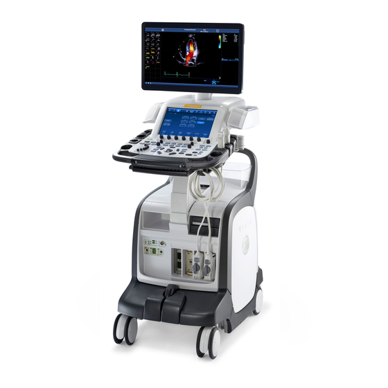
Manual Overview Product description Overview of the Vivid E80/E90/E95 Ultrasound system This Vivid E80/E90/E95 is a high performance digital ultrasound imaging system with total data management. The Ultrasound system provides image generation in 2D, Color Doppler, Power Doppler, M-Mode, Color M-Mode, PW and 4D, Tissue Velocity imaging, and Contrast applications. -
Page 34: Important Conventions
Important conventions, used in this document, are described below. Model designations This manual covers the Ultrasound systems listed in: ‘Vivid E80/E90/E95 models covered by this manual’ on page 1-2. Icons Pictures, or icons, are used wherever they will reinforce the printed message. - Page 35 Notes are used to provide important information about an item or a procedure. NOTE: Be sure to read the notes; the information contained in a note can often save you time or effort. – Vivid E80/E90/E95 Service Manual GC091052 Rev. 3...
-
Page 36: Standard Hazard Icons
Table 1-2: Standard hazard icons ELECTRICAL MECHANICAL RADIATION LASER HEAT PINCH NOTE: Even if a symbol isn’t used on the product or in this manual, it may be included for your reference. – Vivid E80/E90/E95 Service Manual GC091052 Rev. 3... -
Page 37: Product Icons
Avoid Static Electricity Tag and Lock Out Wear Eye Protection Hand Protection Foot Protection Wear Eye Protection Product icons Refer to the Device labels in the Safety chapter in the User Manual. – Vivid E80/E90/E95 Service Manual GC091052 Rev. 3... -
Page 38: Safety Considerations
Local laws may restrict this device for sale or use by or on the order of a physician. NOTE: For Vivid E80/E90/E95 Vet, local laws may restrict this device for sale or use by or on the order of a veterinarian. DANGER DANGEROUS VOLTAGES, CAPABLE OF CAUSING DEATH, ARE PRESENT IN THIS EQUIPMENT. - Page 39 Safety considerations Have two people available to deliver and unpack the Vivid E80/ WARNING E90/E95. Attempts to move the Vivid E80/E90/E95 considerable distances or on an incline by one person could result in injury or damage or both. Explosion Warning WARNING DO NOT operate the equipment in an explosive atmosphere.
- Page 40 Beware of possible sharp edges on all mechanical parts. If WARNING sharp edges are encountered, the appropriate PPE should be used to reduce the risk of injury. Wear all PPE including gloves as indicated in the chemical WARNING MSDS. 1-10 – Vivid E80/E90/E95 Service Manual GC091052 Rev. 3...
-
Page 41: Mechanical Safety
Remember: If the front caster swivel lock is engaged for WARNING transportation, pressing the release pedal once disengages the swivel lock. You must depress the release pedal a second time to engage the brake. – 1-11 Vivid E80/E90/E95 Service Manual GC091052 Rev. 3... - Page 42 Keep the heat venting holes on the monitor unobstructed to CAUTION avoid overheating of the monitor. Vivid E80/E90/E95 weighs 128 kg (283 lb.) or more, depending CAUTION on installed peripherals, when ready for use. Care must be used when moving it or replacing its parts.
- Page 43 Safety considerations Do not transport Vivid E80/E90/E95 in a vehicle without locking CAUTION the casters (wheels) and securing it as described in chapter 4. Use protective glasses during drilling, filing smooth CAUTION surfaces, and during all other work where eyes need protection.
-
Page 44: Electrical Safety
The power outlet used for this equipment should not be shared with other types of equipment. • Both the Vivid E80/E90/E95 power cable and the power connector must meet international electrical standards Connecting a Vivid E80/E90/E95 to the wrong voltage level will WARNING most likely destroy it. 1-14 –... - Page 45 • Never immerse the probe connector or adapter into any liquid. • The Vivid E80/E90/E95 has more than one type of probe port. Use the appropriate probe port designed for the probe you are connecting. Peripherals Refer to the Patient Safety Environment section of the User’s Manual for peripheral isolation information.
-
Page 46: Dangerous Procedure Warnings
DEATH, ARE PRESENT IN THIS EQUIPMENT. USE EXTREME CAUTION WHEN HANDLING, TESTING AND ADJUSTING. If the covers are removed from an operating Vivid E80/E90/ WARNING E95, some metal surfaces may be warm enough to pose a potential heat hazard if touched, even while in shutdown mode. -
Page 47: Lockout/Tagout (Loto) Requirements
5. Control all stored and residual energy. 6. Verify isolation. All potentially hazardous stored or residual energy is relieved. Energy Control and Power Lockout for Vivid E80/E90/E95. WARNING When servicing parts of the Ultrasound system where there is exposure to voltage greater than 30 volts: 1. -
Page 48: Returning Probes And Repair Parts
The USER/SERVICE staff should dispose of all the waste properly, per federal, state, and local waste disposal regulations. The Vivid E80/E90/E95 is not meant to be used for long-term storage of patient data or images. The user is responsible for the data on the Vivid E80/E90/E95 and a regular backup is highly recommended. -
Page 49: Electromagnetic Compatibility (Emc)
Compliance Vivid E80/E90/E95 conforms to all applicable conducted and radiated emission limits and to immunity from electrostatic discharge, radiated and conducted RF fields, magnetic fields and power line transient requirements. -
Page 50: Electrostatic Discharge (Esd) Prevention
ESD sensitive parts. All parts that have the potential for storing energy must be discharged or isolated before making contact. If the covers are removed from an operating Vivid E80/E90/ WARNING E95, some metal surfaces may be warm enough to pose a potential heat hazard if touched, even while in shutdown mode. -
Page 51: Customer Assistance
10. Where applicable, save the appropriate log files. Remember to save the log files for each day on a separate media, labelled accordingly. NOTE: Restart the application before resuming clinical scanning. – 1-21 Vivid E80/E90/E95 Service Manual GC091052 Rev. 3... -
Page 52: Phone Numbers For Customer Assistance
Introduction Phone numbers for Customer Assistance Table 1-4: Phone Numbers for Customer Assistance 1-22 – Vivid E80/E90/E95 Service Manual GC091052 Rev. 3... -
Page 53: System Manufacturer
Customer assistance System manufacturer Table 1-5: System manufacturer MANUFACTURER PHONE NUMBER FAX NUMBER GE VINGMED ULTRASOUND A/S +47 3302 1100 +47 3302 1350 STRANDPROMENADEN 45 P.O. BOX 141 NO-3191 HORTEN NORWAY – 1-23 Vivid E80/E90/E95 Service Manual GC091052 Rev. 3... - Page 54 Introduction THIS PAGE WAS INTENTIONALLY LEFT BLANK 1-24 – Vivid E80/E90/E95 Service Manual GC091052 Rev. 3...
-
Page 55: Chapter 2 - Site Preparations
This chapter provides the information required to plan and prepare for the setup of an Ultrasound system. Included are descriptions of the facility and electrical needs to be met by the purchaser of the Ultrasound system. – Vivid E80/E90/E95 Service Manual GC091052 Rev. 3... -
Page 56: General Ultrasound System Requirements
If the Ultrasound system is very cold or hot, do not turn on its CAUTION power until it has had a chance to acclimate to its operating environment. Table 2-1: Ultrasound system acclimate time – Vivid E80/E90/E95 Service Manual GC091052 Rev. 3... - Page 57 (-4 to +140 °F) non-condensing Cooling The cooling requirement for the Vivid E80/E90/E95 with monitor and on board peripherals, is up to 2390 BTU/h. This figure does not include cooling needed for lights, people, or other equipment in the room.
-
Page 58: Electrical Requirements
Site Preparations Electrical requirements General requirements NOTE: GE requires a dedicated power and ground for the proper operation of its Ultrasound equipment. This dedicated power shall originate at the last distribution panel before the Ultrasound system. The Vivid E80/E90/E95 will function on voltages from 100-240 Volts and 50 or 60 Hz. - Page 59 General Ultrasound system requirements Electrical requirements for the Vivid E80/E90/E95 In the table below, the electrical specifications for the Vivid E80/ E90/E95 includes monitor and on-board peripherals. The specifications apply for the following models: • GC000220 - Vivid E95 •...
- Page 60 Site Preparations Power plug If the Ultrasound system arrives without a power plug, or with the wrong plug, you must contact your GE dealer or the installation engineer must supply what is locally required. Power stability requirements Voltage drop-out: Max 10 ms.
-
Page 61: Emi Limitations
High Frequency (HF) surgery equipment • general AC/DC adapters The presence of a broadcast station or broadcast van may also cause interference. See: ‘EMI prevention/abatement’ on page 2-8 for EMI prevention tips. – Vivid E80/E90/E95 Service Manual GC091052 Rev. 3... -
Page 62: Emi Prevention/Abatement
Radio Frequency leakage. Or, if a touch metal label has been found in such a position, move the label. Use GE specified The interconnect cables are grounded and require ferrite harnesses and beads and other shielding. Also, cable length, material, and peripherals routing are all important;... -
Page 63: Probes Environmental Requirements
+50 degrees C (-4 to +122 degrees F). When exposed to large temperature variations, the product should be kept at room temperature the needed time to stabilize its temperature before use. – Vivid E80/E90/E95 Service Manual GC091052 Rev. 3... -
Page 64: Facility Needs
• Procuring the materials required • Completing the preparations before delivery of the Ultrasound system • Paying the costs for any alterations and modifications not specifically provided in the sales contract 2-10 – Vivid E80/E90/E95 Service Manual GC091052 Rev. 3... - Page 65 All electrical work on these products must comply with the requirements of applicable electrical codes. The purchaser of GE equipment must only utilize qualified personnel to perform electrical servicing on the equipment. The desire to use a non–listed or customer provided product or...
-
Page 66: Required Facility Needs
Site Preparations Required facility needs NOTE: GE requires a dedicated power and ground for the proper operation of its Ultrasound equipment. This dedicated power shall originate at the last distribution panel before the Ultrasound system. The Ultrasound system will function on voltages from 100-240 Volts and 50 or 60 Hz. -
Page 67: Desirable Features
• Nearby waiting room, lavatory, and dressing room • Dual level lighting (bright and dim) • Lockable cabinet ordered by GE for its software and proprietary manuals Minimal floor plan suggestion Scale: Each square equals one square foot (app. 31 x 31 cm) 1. -
Page 68: Recommended Floor Plan Suggestion
Dual Level Lighting (bright of Ultrasound system from inches) and dim) wall or objects 7. Emergency Oxygen 13. Stool Figure 2-2. Recommended floor plan, 4.27 x 5.18 m (14 x 17 foot) 2-14 – Vivid E80/E90/E95 Service Manual GC091052 Rev. 3... -
Page 69: Suggested Floor Plan, Ultrasound System, And Echopac Pc In Same Room
Stand alone Ultrasound system (without network connection) None. Ultrasound system connected to hospital’s network Supported networks: 10/100/1000 Mbit Ethernet/DICOM network (option) InSite requirements InSite requires an Ethernet connection either via: • 10/100 Mbit or 10/100/1000 Mbit Interface – 2-15 Vivid E80/E90/E95 Service Manual GC091052 Rev. 3... - Page 70 Ultrasound system for DICOM APPLICATION INFORMATION. A field for the make (manufacturer) and the revision of the device, is also included. This information may be useful for error solving. 2-16 – Vivid E80/E90/E95 Service Manual GC091052 Rev. 3...
- Page 71 Facility needs Figure 2-4. Worksheet for DICOM Network Information – 2-17 Vivid E80/E90/E95 Service Manual GC091052 Rev. 3...
-
Page 72: Environmental Dangers
This encloses a space within the room 1.83 m (6 ft.) beyond the perimeter of the bed (examination table, dental chair, treatment booth, and the like) in its intended location, and extending vertically 2.29 m (7.5 ft.) above the floor. 1. Patient environment 2-18 – Vivid E80/E90/E95 Service Manual GC091052 Rev. 3... -
Page 73: Patient Environment Iec60601-1 (Iec60601-1-1) And Ansi Aami
Patient Environment. The patient environment/vicinity will be depicted as a dashed line in this procedure. See example below. 1. Patient environment Figure 2-5. Patient environment – 2-19 Vivid E80/E90/E95 Service Manual GC091052 Rev. 3... - Page 74 Site Preparations THIS PAGE WAS INTENTIONALLY LEFT BLANK 2-20 – Vivid E80/E90/E95 Service Manual GC091052 Rev. 3...
-
Page 75: Chapter 3 - System Setup
How to prepare the facility and Ultrasound system of the actual installation, and how to check and test the Ultrasound system, probes, and external peripherals for electrical safety are also included in this procedure. – Vivid E80/E90/E95 Service Manual GC091052 Rev. 3... -
Page 76: Setup Reminders
30 V peak is present. Do not operate this Ultrasound system unless all board covers CAUTION and frame panels are securely in place. System performance and cooling require this. – Vivid E80/E90/E95 Service Manual GC091052 Rev. 3... - Page 77 Operator Manual(s) CAUTION The User Manual(s) should be fully read and understood before operating the Vivid E80/E90/E95 and kept near the Ultrasound system for quick reference. Acoustic Output Hazard CAUTION Although the ultrasound energy transmitted from the Vivid E80/ E90/E95 probe is within AIUM/NEMA standards, avoid unnecessary exposure.
-
Page 78: Receiving And Unpacking The Equipment
Two people are required whenever a part weighing 16 KG (35 LBS) or more must be lifted. Remember to use relevant personal protecting equipment CAUTION (PPE) during packing and unpacking. Check with your local EHS representative. – Vivid E80/E90/E95 Service Manual GC091052 Rev. 3... -
Page 79: The Tilt And Shock Indicators
To make it easier to detect if the handling during transportation has been improper, a set of Tilt & Shock indicators have been attached to the transportation box. Table 3-1: Shock and Tilt Watch Description Illustration ShockWatch Tilt Watch – Vivid E80/E90/E95 Service Manual GC091052 Rev. 3... - Page 80 Shock Indicator label is missing. If the Shock Indicator has triggered: Note on the shipping papers at the time of receipt that the Shock Indicator label was activated. Inspect the product for possible concealed damage. – Vivid E80/E90/E95 Service Manual GC091052 Rev. 3...
- Page 81 Tilt Indicator label is missing. If the Tilt Indicator has triggered: Note on the shipping papers at the time of receipt that the Tilt Indicator label was activated. Inspect the product for possible concealed damage. – Vivid E80/E90/E95 Service Manual GC091052 Rev. 3...
-
Page 82: Receiving The Vivid E80/E90/E95
System Setup Receiving the Vivid E80/E90/E95 Examine all packages Examine package closely at time of delivery, as described in the procedure below. Table 3-4: Examine all packages Step Task Illustrations Is damage apparent? • If YES; continue with the instructions in ‘Damage in transportation’... - Page 83 3-10 before you continue with the next step. • If NO: continue with the next step. 1 - Red Color Continue with the instructions in ‘Unpacking the Vivid E80/E90/E95’ on page 3-11. – Vivid E80/E90/E95 Service Manual GC091052 Rev. 3...
- Page 84 Follow this procedure if damage is apparent: 1. Write “Damage In Shipment” on ALL copies of the freight or express bill BEFORE delivery is accepted or “signed for“ by a GE representative or hospital receiving agent. 2. Report the damage to the carrier. •...
-
Page 85: Unpacking The Vivid E80/E90/E95
Receiving and unpacking the equipment Unpacking the Vivid E80/E90/E95 This procedure describes how to unpack the Vivid E80/E90/E95 from the cardboard box. Before cutting the straps, check Shock and Tilt Tags to make sure they have not been triggered. If damaged, report it to the carrier. - Page 86 System Setup Table 3-5: Uncrating the Vivid E80/E90/E95 (Cont'd) Step Task Illustration Remove the two Frames (sides) and the two Exit Ramp Bases. Install the two Exit Ramp Bases on the Complete Exit Ramp (the rear plate). 3-12 – Vivid E80/E90/E95 Service Manual GC091052 Rev.
- Page 87 Receiving and unpacking the equipment Table 3-5: Uncrating the Vivid E80/E90/E95 (Cont'd) Step Task Illustration Remove the Support For Monitor. Remove the Complete Front Protection. Remove the plastic bag from the Vivid E80/E90/E95. Remove the Inlay UI Top. – 3-13...
- Page 88 System Setup Table 3-5: Uncrating the Vivid E80/E90/E95 (Cont'd) Step Task Illustration Fold down the assembled Exit Ramp. Unlock the Front Brakes on the Vivid E80/E90/E95, but keep direction lock activated. The direction lock keeps the front wheels in position, and...
-
Page 89: Packing Materials - Recycling Information
Packing materials - recycling information Packing materials - recycling information The packing materials for Vivid E80/E90/E95 are recyclable: Table 3-6: Packaging parts for Vivid E80/E90/E95 Item Description Qty. Material *) Illustration Export pallet 1200 x 800 Complete base Complete column left and... - Page 90 System Setup Table 3-6: Packaging parts for Vivid E80/E90/E95 (Cont'd) Item Description Qty. Material *) Illustration Exit ramp Frame Exit ramp base Box for accessories Top cover 1140 x 755 x 150 Support plate, used to keep Front Protection in place if there are few or none probes included.
-
Page 91: Preparing For Setup
Physical inspection Verify that the Vivid E80/E90/E95 arrived intact (visual inspection). If the Vivid E80/E90/E95 has been damaged, please refer to ‘Damage in transportation’ on page i-15 in the beginning of this manual. EMI protection The Vivid E80/E90/E95 has been designed to minimize the effects of Electro-Magnetic Interference (EMI). -
Page 92: Completing The Setup
Depth Unit 141.0 58.5 83.0 55.5 32.7 Inches Mass with monitor and peripherals Table 3-8: Mass of Vivid E80/E90/E95 with monitor, without probes and peripherals Model Mass [KG] Mass [LBS] Vivid E80/E90/ 3-18 – Vivid E80/E90/E95 Service Manual GC091052 Rev. 3... -
Page 93: Electrical Specifications
Verification of the Vivid E80/E90/E95’s voltage setting Verify that the mains voltage specified for the Vivid E80/E90/E95 is available on-site. The voltage setting for the Vivid E80/E90/E95 is found on a label near the Mains Power Circuit Breaker on the rear of the Vivid E80/E90/E95. -
Page 94: Connections On The I/O Rear Panel
Connect Ethernet Connect the network cable to the Ethernet connector on the I/O Rear Panel. The connector is located on the rear side of Vivid E80/E90/E95. Connect USB Flash Card NOTE: Only approved USB Flash Cards must be used. USB Flash Cards approved for Vivid E80/E90/E95 are verified for EMC performance according to EN55011 class B. -
Page 95: Connections On The Patient I/O Panel
Completing the setup Connections on the Patient I/O panel The Patient I/O panel is located on the front of Vivid E80/E90/ E95. 1. PHONO 2. ECG 3. AUX (PRESSURE/PULSE) Figure 3-1. Patient I/O Panel Connect ECG Connect the ECG cable to the ECG connector on the Patient I/O panel. -
Page 96: Connecting Probes
System Setup Connecting probes Introduction to ‘Connecting probes’ The Vivid E80/E90/E95 has three types of probe ports; one PD probe port, three PDT probe ports and one Doppler probe port. Probes can be connected at any time, whether the Vivid E80/ E90/E95 is On or Off. - Page 97 5. Turn the locking handle clockwise to the full vertical position to lock in place. 6. Position the probe cable so that it is not resting on the floor. – 3-23 Vivid E80/E90/E95 Service Manual GC091052 Rev. 3...
- Page 98 2. Remove the connector from the port. 3. Ensure that the probe head is clean before placing the probe in its storage case. For cleaning instructions, see the User Manual. 3-24 – Vivid E80/E90/E95 Service Manual GC091052 Rev. 3...
-
Page 99: Configuration
Configuration Configuration Vivid E80/E90/E95 configuration Select System Settings screen 1. Select Config (F2) and log on as adm. 2. Select System and then select Settings, if needed. The Settings screen is displayed. Figure 3-4. Settings screen – 3-25 Vivid E80/E90/E95 Service Manual GC091052 Rev. - Page 100 (max 64 • The 24 first characters of this characters). name are displayed on the scanning screen’s title bar. • All 64 are displayed on the image properties on saved images. 3-26 – Vivid E80/E90/E95 Service Manual GC091052 Rev. 3...
- Page 101 (max 64 characters). the image properties on saved images Select the Echolab field and type After restart: the name. • This name will be displayed on the image properties on saved images – 3-27 Vivid E80/E90/E95 Service Manual GC091052 Rev. 3...
- Page 102 YYYY = Year (four digits) Select the preferred Time Format, • 24: the 24 hour format is used see (3) in Figure 3-6. • 12: the 12 AM/PM hour format is used 3-28 – Vivid E80/E90/E95 Service Manual GC091052 Rev. 3...
- Page 103 • the four digits have to be typed when entering the year in the patient date of birth. • The selected setting will be used as soon as the unit has been restarted. – 3-29 Vivid E80/E90/E95 Service Manual GC091052 Rev. 3...
- Page 104 (1). Use the Manual Language pulldown The selected language will be used menu (2) to select the prefered as soon as the unit has been language for the online manual. restarted. 3-30 – Vivid E80/E90/E95 Service Manual GC091052 Rev. 3...
- Page 105 Select the video format from the The selected video format will be Video settings pulldown menu (4 in used as soon as the unit has been Figure 3-7 on page 3-30.) restarted. – 3-31 Vivid E80/E90/E95 Service Manual GC091052 Rev. 3...
-
Page 106: Service Screen Setup
Service Screen setup Open Service Screen 1. Press Config (F2) and log on as ADM. 2. Select Service (lower, right part of window) to view the Service Screen. Figure 3-8. Service screen 3-32 – Vivid E80/E90/E95 Service Manual GC091052 Rev. 3... - Page 107 US keyboard, since the default setting is set to US English keyboards. Table 3-14: Select keyboard STEP TASK EXPECTED RESULT(S) Select Keyboard Setup to get access to Keyboard Properties. Select Keyboards and Languages. – 3-33 Vivid E80/E90/E95 Service Manual GC091052 Rev. 3...
- Page 108 System Setup Table 3-14: Select keyboard (Cont'd) STEP TASK EXPECTED RESULT(S) Select Change Keyboards... Select the keyboard and then select 3-34 – Vivid E80/E90/E95 Service Manual GC091052 Rev. 3...
-
Page 109: Optional Peripherals/Peripheral Connection
Illustration Select Add Printer to start the Add Printer (Installation) Wizard. Follow the instructions in the Wizard to install a new printer. Related information: • ‘Optional peripherals/peripheral connection’ on page 3-36 – 3-35 Vivid E80/E90/E95 Service Manual GC091052 Rev. 3... - Page 110 System Setup Optional peripherals/peripheral connection Approved internal peripherals This list covers the internal peripherals available for Vivid E80/ E90/E95: • Printer, Monochrome (Black & White), Digital SONY UP-D898 • MITSUBISHI Digital Monochrome Printer P95DE Approved external peripherals One of the external units listed below may be connected to the...
-
Page 111: Software Options Configuration
Follow these steps to install the Software Option Key: 1. Press Config (F2) and log on as adm. 2. Select Admin (lower part of window). 3. Select the System Admin tab. – 3-37 Vivid E80/E90/E95 Service Manual GC091052 Rev. 3... - Page 112 Incorrect Software Option Key entry will result in loss of CAUTION functionality. If Software Option Key is not accepted by the Ultrasound system, please contact your local GE Service Representative or the Online Center. 5. Type the Software Option Key. It is case sensitive, and you must include the dashes (-) as they are part of the Software Option Key.
-
Page 113: Connectivity Overview
Connectivity overview Connectivity overview Physical connection There are several possible connection methods, as outlined below. Stand-alone Vivid E80/E90/E95 No network connection needed. “Sneaker Net” environment No network connection needed. Use removable media to move the data. – 3-39 Vivid E80/E90/E95 Service Manual GC091052 Rev. - Page 114 Ultrasound system / workstation • Connection via Hospital Network. You will need one network cable to connect the Vivid E80/ E90/E95 to a wall outlet on the hospital’s network. Connection from Vivid E80/E90/E95 to a DICOM Server on a network You will need one network cable.
-
Page 115: Connectivity Setup
Connectivity setup Connectivity setup Compatibility Vivid E80/E90/E95 can communicate with: • EchoPAC • Image Vault For networks with Image Vault 5 server: If not already done, install the latest version of the Vivid Raw Data Module (RDCM) on the Image Vault server. -
Page 116: Select Tcp/Ip Screen
2. If not already selected, select Connectivity from the bottom row of “buttons” on the screen. 3. Select the TCP/IP TAB (named Tcpip). The resulting screen gives you an overview of many of the network settings for Vivid E80/E90/E95. 1. My Computer: 3. -
Page 117: Changing The Ae Title And/Or Port Number (Port No.)
Figure 3-10. AE Title and Port No. 1. To change AE Title and/or Port No., edit the respective fields. 2. Select Save settings to store your changes. 3. Reboot Vivid E80/E90/E95 to activate the settings, or continue with other Tcpip set-up tasks. – 3-43... -
Page 118: Dhcp Setup
System Setup DHCP setup Follow the instructions below to configure the Vivid E80/E90/ E95’s use of DHCP: 1. When in the TCP/IP screen, select Network Settings to display the Network Connections screen. Figure 3-11. Network Connections 2. Right-click Local Area Connection and select Properties from the pop-up menu to go to the Local Area Connection Properties screen (see next page). - Page 119 DHCP setup (continued) 3. Select Properties to display the Local Area Connection Properties Figure 3-13. Local Area Connection Properties 4. Select Internet Protocol (TCP/IP), then select Properties. Figure 3-14. Internet Protocol (TCP/IP) Properties – 3-45 Vivid E80/E90/E95 Service Manual GC091052 Rev. 3...
- Page 120 2. Select OK to close (and save) the Local Area Connection Properties dialog. 3. Select Close to close the Local Area Connection Status dialog. 4. Select the “x” in the upper right corner to close the Network Connections window. 3-46 – Vivid E80/E90/E95 Service Manual GC091052 Rev. 3...
-
Page 121: Set The Remote Archive's Network Information
Set the Remote Archive’s Network Information To be able to connect to a remote archive on a remote computer or server, you must configure Vivid E80/E90/E95 to communicate with it. The configuration is done in the Server Config setup area on the Tcpip screen. - Page 122 A green check mark next to the Check button indicates that the IP-Address was found on the network. • A red mark indicates that the IP address was not found. Troubleshooting tips: 3-48 – Vivid E80/E90/E95 Service Manual GC091052 Rev. 3...
-
Page 123: Save The New Settings
1. Press Save Settings to save the new settings. The new settings are saved to a common settings file. After a restart, the settings are also included in other screens. 2. Restart Vivid E80/E90/E95 to activate the changes. – 3-49... -
Page 124: Product Locator Installation Card
Product Locator card. From the factory, a sheet with five Product Locator cards for transportation and one for Installation are included. Figure 3-17. Product Locator Installation Card (Example) 3-50 – Vivid E80/E90/E95 Service Manual GC091052 Rev. 3... -
Page 125: Chapter 4 - General Procedures And Functional Checks
Functional Checks is a collection of procedures for quickly checking major functions of the Vivid E80/E90/ E95 and diagnostics instructions using the built-in service software. These checks can be a great asset in determining whether the Vivid E80/E90/E95 is working as it should. -
Page 126: General Procedures
Ultrasound system performance, and cooling purposes. Use only power supply cords, cables, and plugs provided or CAUTION designated by GE. NOTE: Do not cycle the Circuit Breaker ON-OFF-ON in less than five (5) seconds. When turning OFF the Circuit Breaker, the Ultrasound system should de-energize completely before turning the circuit breaker ON. - Page 127 General procedures Connect AC (mains) Power to the Vivid E80/E90/E95 Connecting AC Power to the Vivid E80/E90/E95 ultrasound unit, involves preliminary checks of the power cord, voltage level and compliance with electrical safety requirements. 1. Ensure that the wall outlet is of appropriate type, and that the Circuit Breaker is turned off.
- Page 128 General Procedures and Functional Checks Switch ON the AC Power to Vivid E80/E90/E95 1. Switch ON the Mains Power Circuit Breaker at the rear of the unit. You should hear a “click” from the relays in the AC Power and the unit is ready to boot.
-
Page 129: Power Shut Down
Select this button when you want to exit to the Windows Desktop. NOTE: If you need to restart Vivid E80/E90/E95 when logged on to the Windows Desktop, ensure that you do a complete power down (Shut Down). This is required to power up the Front End Processor. - Page 130 General Procedures and Functional Checks Power shut down (continued) • Cancel Use this button to exit from the System-Exit menu and return to the previous operation. – Vivid E80/E90/E95 Service Manual GC091052 Rev. 3...
-
Page 131: Complete Power Down
Complete power down 1. Before Power Down, lock the Top Console in its lower, locked position. This is required if you are going to move or transport the Vivid E80/E90/E95 to ensure maximum stability. NOTE: For service purposes, you may want to move the Top Console after Power Down. -
Page 132: Creating Presets
4. Switch off the Mains Power Circuit Breaker, located on the rear of the Ultrasound system. This will cut power distribution within the Vivid E80/E90/E95. Figure 4-4. Circuit Breaker located at the rear of the Vivid E80/ E90/E95 Creating presets Refer to the latest revision of the Vivid E80/E90/E95 User Manual. -
Page 133: Functional Checks
Introduction The 2D Mode is the Ultrasound system’s default mode. Preparations 1. Connect one of the probes. 2. Turn ON the Vivid E80/E90/E95. The 2D Mode window is displayed (default mode). 1. Probe orientation marker 2. Parameter window Figure 4-5. The 2D screen (cardiac) –... - Page 134 General Procedures and Functional Checks Preparations (continued) Figure 4-6. 2D Touch panel (4D probe Live) page 1 and 2 4-10 – Vivid E80/E90/E95 Service Manual GC091052 Rev. 3...
- Page 135 • Use the Gain and TGC controls to optimize the overall image. Gain increases or decreases the amount of echo information displayed. TGC compensates for depth-related attenuation in the image. – 4-11 Vivid E80/E90/E95 Service Manual GC091052 Rev. 3...
- Page 136 • Adjust the Rotate rotary of the Touch panel to fine tune the angle adjustment. A scan plane indicator is displayed showing the angle position of the scan plane. 4-12 – Vivid E80/E90/E95 Service Manual GC091052 Rev. 3...
-
Page 137: M Mode Checks
It is not to be used for measurements or analysis. This is not an absolute value, but simply a reference number. Users performing studies using standardized protocols may find this sweep speed information useful for reading studies from other institutions. Figure 4-7. The M-Mode screen (composite) – 4-13 Vivid E80/E90/E95 Service Manual GC091052 Rev. 3... - Page 138 General Procedures and Functional Checks Figure 4-8. M-Mode Touch panel page 1 and 2 4-14 – Vivid E80/E90/E95 Service Manual GC091052 Rev. 3...
- Page 139 2D images. More than one heart cycle should be stored if performing M-Mode in post processing. 2. Use the trackball (assigned function: Pos) to position the cursor over the required area of the image. – 4-15 Vivid E80/E90/E95 Service Manual GC091052 Rev. 3...
- Page 140 Adjust Dynamic range to optimize the useful range of incoming echoes to the available grayscale. • Adjust Compress to further optimize the display. • Adjust Reject to reduce noise while taking care not to eliminate significant low-level diagnostic information. 4-16 – Vivid E80/E90/E95 Service Manual GC091052 Rev. 3...
-
Page 141: Color Mode Checks
Color Flow may be selected both from 2D mode or from M mode or a combination of these. Color 2D Mode overview 1. Probe orientation marker 2. Color bar 3. Color sector marker 4. Parameter window Figure 4-9. The Color Mode screen – 4-17 Vivid E80/E90/E95 Service Manual GC091052 Rev. 3... - Page 142 General Procedures and Functional Checks Figure 4-10. Color 2D Touch panel page 1 and 2 4-18 – Vivid E80/E90/E95 Service Manual GC091052 Rev. 3...
- Page 143 Color M-Mode overview 1. Time motion cursors (M-Mode, AMM and Curved AMM) 2. Color bar 3. Flow sector marker 4. Time scale 5. Parameter window Figure 4-11. The Color M-Mode screen (composite) – 4-19 Vivid E80/E90/E95 Service Manual GC091052 Rev. 3...
- Page 144 General Procedures and Functional Checks Figure 4-12. Color M-Mode Touch panel page 1 and 2 (Color controls) 4-20 – Vivid E80/E90/E95 Service Manual GC091052 Rev. 3...
-
Page 145: Pw/Cw Doppler Mode Checks
Doppler mode can be done with a special pencil probe or with an ordinary probe. By using an ordinary probe, you can first bring up a 2D picture for navigation purpose and then add PW/ CW Doppler. – 4-21 Vivid E80/E90/E95 Service Manual GC091052 Rev. 3... - Page 146 It is not to be used for measurements or analysis. This is not an absolute value, but simply a reference number. Users performing studies using standardized protocols may find this sweep speed information useful for reading studies from other institutions. Figure 4-13. The PW/CW Doppler Mode screen 4-22 – Vivid E80/E90/E95 Service Manual GC091052 Rev. 3...
- Page 147 Functional checks Figure 4-14. The PW Doppler Touch panels page 1and 2 Related information: Refere to the Vivid E80/E90/E95 User Manual. – 4-23 Vivid E80/E90/E95 Service Manual GC091052 Rev. 3...
- Page 148 • Adjust Frame rate to a higher setting to improve motion detection, or to a lower setting to improve resolution. 4-24 – Vivid E80/E90/E95 Service Manual GC091052 Rev. 3...
-
Page 149: Tissue Velocity Imaging (Tvi) Checks
Auto is pressed. Tissue Velocity Imaging (TVI) Checks Introduction TVI calculates and color codes the velocities in tissue. The tissue velocity information is acquired by sampling of tissue – 4-25 Vivid E80/E90/E95 Service Manual GC091052 Rev. 3... - Page 150 TVI overview 1. TVI color bar 2. Parameter window Figure 4-15. The TVI Mode screen 4-26 – Vivid E80/E90/E95 Service Manual GC091052 Rev. 3...
- Page 151 Tissue Velocity Imaging (TVI) calculates and color-codes the velocities in tissue. The tissue velocity information is acquired by sampling of tissue Doppler velocity values at discrete points. The information is stored in a combined format with grayscale – 4-27 Vivid E80/E90/E95 Service Manual GC091052 Rev. 3...
- Page 152 However, from this window the beam cannot be aligned with the muscle for all the parts of the ventricle. NOTE: PW will be optimized for Tissue Velocities when activated from inside TVI. 4-28 – Vivid E80/E90/E95 Service Manual GC091052 Rev. 3...
-
Page 153: Probe/Connectors Checks
Test the probe in each active It will display pictorial data each connector slot. time. Do a leakage test on the probe. It passes the test. Repeat this procedure for all available probes. – 4-29 Vivid E80/E90/E95 Service Manual GC091052 Rev. 3... -
Page 154: Ecg Check
When the connection is completed, a typical clean ECG signal is Fasten the three ECG Pads to your displayed. body and connect the three leads to respective ECG Pad. 4-30 – Vivid E80/E90/E95 Service Manual GC091052 Rev. 3... -
Page 155: Cineloop Check
1. Left marker (cineloop start) 3. Right marker (cineloop end) 2. Current frame 4. Cine speed Figure 4-17. Cineloop display Preparation 1. Connect one of the probes to the Ultrasound system. – 4-31 Vivid E80/E90/E95 Service Manual GC091052 Rev. 3... -
Page 156: Back End Processor Checks
If all the previous tests have been passed successfully, the Back End Processor is most likely OK. • If the Ultrasound system seems to be operating erratically, please refer to Chapter 7 in this manual. 4-32 – Vivid E80/E90/E95 Service Manual GC091052 Rev. 3... -
Page 157: Operating Panel Test
Functional checks Operating Panel Test • The Operating Panel is tested when the Vivid E80/E90/E95 is powered up as part of the start-up scripts, run at every start-up. Related information: • ‘Troubleshooting’ on page 7-8 Peripheral checks Printer checks The internal printer is controlled from the P1 and P2 keys on the Vivid E80/E90/E95’s Operating Panel. - Page 158 9. Click on the “>>” button. This will place this service in the PrintFlow View for the printer button you selected. 10. Click on Save. You have now configured a printer service and attached it to a print button. 4-34 – Vivid E80/E90/E95 Service Manual GC091052 Rev. 3...
-
Page 159: Mechanical Functions Checks
“Control panel adjustment” in the user manual and to: • “To unlock/lock the LCD monitor” in the User Manual. Casters (Wheels), Brakes and Direction Lock checks Please refer to: “The Casters (Wheels) control” in the user manual. – 4-35 Vivid E80/E90/E95 Service Manual GC091052 Rev. 3... - Page 160 General Procedures and Functional Checks THIS PAGE WAS INTENTIONALLY LEFT BLANK 4-36 – Vivid E80/E90/E95 Service Manual GC091052 Rev. 3...
-
Page 161: Chapter 5 - Components And Functions (Theory)
Chapter 5 Components and Functions (Theory) This chapter explains Vivid E80/E90/E95’s system concepts, component arrangement, and subsystem functions. It also describes the power distribution and the Common Service Desktop interface. – Vivid E80/E90/E95 Service Manual GC091052 Rev. 3... -
Page 162: Software Overview
It is based on Windows 7 Embedded and is delivered on the software and documentation Usb Flash Drive (UFD). For software versions, see: ‘Software for Vivid E80/E90/E95’ on page 9-4. Application software The Application Software includes all the functionality for Vivid E80/E90/E95. -
Page 163: Insite Exc
InSite ExC InSite ExC Introduction InSite ExC is your direct link with a GE Online Service Engineer or Applications Support Engineer, or a Request for Service via the InSite ExC link at the bottom of the display screen. InSite ExC Icon The InSite ExC icon in the status bar change symbol and color depending on ongoing activity. -
Page 164: Insite Exc Status
Connected Red Icon with clock - InSite ExC activated. Disrupted State - Online Center Is Connected Red Icon with GE Logo - InSite ExC activated and Technical Support can look around on your Ultrasound system, run diagnostics, gather logs, and initiate VCO. -
Page 165: Insite Exc Definitions
There are two disruptive states. If you see a telephone with a clock, then the Ultrasound system is in Disruptive, Not Connected Mode. If you see a telephone with GE, then the Ultrasound system is in Disruptive, Connected Mode. Non-Disruptive. Allows GE's Technical support person to look... -
Page 166: Initiating A Request For Service (Rfs)
Initiating a Request for Service (RFS) To initiate an RFS, 1. Position the Windows pointer on top of the GE InSite ExC icon at the bottom of the display. 2. Press the Right Trackball Set Key. Press Contact GE. This... - Page 167 After you press Send, the following pop-up appears: Figure 5-3. Request for Service Confirmation All requests for service are listed on the Queue for your review. Figure 5-4. Request for Service Queue – Vivid E80/E90/E95 Service Manual GC091052 Rev. 3...
- Page 168 Components and Functions (Theory) Initiating a Request for Service (RFS) (continued) You can monitor your RFS as well as RFS’s automatically sent by the system. The Vivid E80/E90/E95 can automatically submit a Request for Service. These are displayed on the Machine Queue.
-
Page 169: Exiting Insite Exc
To exit InSite ExC, 1. Press the Left Trackball Set key. 2. Select Connect To GE. 3. Press the Right Trackball Set key. The GE Technical Support person then exits Disruptive Mode and VCO. 4. Reboot your Ultrasound system. –... -
Page 170: Vivid E80/E90/E95 Overview
Components and Functions (Theory) Vivid E80/E90/E95 overview Introduction The Vivid E80/E90/E95 is a high performance digital ultrasound imaging system with total data management. The Ultrasound system provides image generation in 4D, 2D (B) Mode, Color Doppler, Power Doppler (Angio), M-Mode, Color M-Mode, PW and CW Doppler spectra, Tissue Velocity imaging, advanced Strain and Contrast applications. -
Page 171: Vivid E80/E90/E95 Block Diagram
Vivid E80/E90/E95 overview Vivid E80/E90/E95 block diagram Figure 5-7. Vivid E80/E90/E95 block diagram – 5-11 Vivid E80/E90/E95 Service Manual GC091052 Rev. 3... -
Page 172: Signal Flow Overview
TGC and an LCD touch display. An alphanumeric keyboard is located as a drawer below the Operating Panel. The electronics The signal processing electronics in Vivid E80/E90/E95 is divided into two card cages: • Front End Processor (FEP) The FEP is sometimes called “Front End Card Cage”, “Front... -
Page 173: Operating Modes
• Strain • Tissue Synchronization Imaging (TSI) • 4D and Multi-plane Modes For information about the different scanning modes, refer to the following chapters in the Vivid E80/E90/E95 User Manual: • Scanning Modes • 4D and Multi-plane Modes – 5-13... -
Page 174: Top Console Description
Measure & Analyze (M&A) • an alphanumeric keyboard (QWERTY keyboard) on a drawer below the switch board. • speakers for stereo sound output used during Doppler scanning/replay 5-14 – Vivid E80/E90/E95 Service Manual GC091052 Rev. 3... - Page 175 Top Console with LCD monitor and Operating Panel Top Console’s location in the Vivid E80/E90/E95 The Top Console is located on the top of the Vivid E80/E90/E95, and includes the Main LCD monitor, the Monitor Arm, the Operating Panel with the Touch Screen, speakers and an alphanumeric keyboard as an drawer below the Operating Panel.
- Page 176 Components and Functions (Theory) Connection from the Top Console to the rest of the Vivid E80/E90/E95 A flexible harness of electrical wires secures the connection between the Top Console and the rest of the Vivid E80/E90/E95. The XYZ mechanism The Top Console can be adjusted without moving the complete Ultrasound system.
- Page 177 The Threaded Lead Screw (4) then rotates clockwise and returns to its original position. This is shown in the Figure below. Figure 5-10. Unlocked position When the Operating Panel moves into locked position a micro switch (1) is activated. – 5-17 Vivid E80/E90/E95 Service Manual GC091052 Rev. 3...
- Page 178 The micro switch activation is used by the Motor Controller to detect when the Operating Panel is in locked position. The XY (frogleg) brakes will stay ON if the Vivid E80/E90/E95 is powered down when the Operating Panel is locked. This enables release of the Park Lock, initiated by the micro switches on the Front Handle of the Operating Panel.
- Page 179 5. Scan mode selection 14. TGC sliders 6. Zoom 15. Loudspeaker volume control 7. Depth 16. Touch panel with adjustment rotaries 8. Display controls and Annotation Figure 5-11. The Operating Panel – 5-19 Vivid E80/E90/E95 Service Manual GC091052 Rev. 3...
-
Page 180: Key Illumination
Archive windows displays an error. Also available from Utility/ Spooler on the Touch panel. 5-20 – Vivid E80/E90/E95 Service Manual GC091052 Rev. 3... -
Page 181: Main Console
I/O Rear Panel (BEP I/O Board) • Optional B/W printer • Power Supply • Lifting mechanism for the Frog Leg and Top Console • Rear handle • Front and Rear Casters with lock and brake mechanism – 5-21 Vivid E80/E90/E95 Service Manual GC091052 Rev. 3... -
Page 182: Air Flow Control
Air Flow control Air Flow components The Air Flow control includes the following components: • air filter in the air intake on the back of the Vivid E80/E90/ • fans inside the Vivid E80/E90/E95 • temperature sensors several places inside the Vivid E80/ E90/E95 •... -
Page 183: Location
Location Table 5-2: Location ITEM DESCRIPTION LOCATION Air Filter on the rear of the Vivid E80/E90/E95 Fan unit below Vivid E80/E90/E95’s Card Rack (Front End Rack). Temperature sensors distributed on the cards in the Card Rack (Front End Rack). –... -
Page 184: Casters And Brakes
Components and Functions (Theory) Casters and brakes Casters and brakes description The Vivid E80/E90/E95 has four casters (wheels), two Front Casters and two Rear Casters. • All Casters are mounted on swivels so they can change direction as needed. •... -
Page 185: Front End Processor (Fep)
If the power is turned on with a card placed in the wrong position, the Vivid E80/E90/E95 will be destroyed. FEP’s location The FEP is located on the right side of the Vivid E80/E90/E95, behind the Right Side Cover. FEP cards overview These cards are included in the FEP: •... - Page 186 Figure 5-13. LEDs on GTX-192 Table 5-3: LEDs on the GTX-192 board Color Description Comments DAVID_RESET Green DCM_LOCKED Green VSS, VDD_DR1 & VLL Start up: Lit GOOD Normal Operation: Lit Green TX_TRIGGER Lit during scanning 5-26 – Vivid E80/E90/E95 Service Manual GC091052 Rev. 3...
- Page 187 Description Comments Green DIGITAL POWER GOOD Start up: Lit Normal Operation: Lit FPGA_CTRL_REG(0) DAVID_ERROR GLOBAL_RESET DAVID_CRC_ERROR DS10 Yellow CW MODE LED Lit in CW mode DS11 Green INIT_B Green DONE DS12 – 5-27 Vivid E80/E90/E95 Service Manual GC091052 Rev. 3...
-
Page 188: Relay Board (Grly)
Relay board (GRLY) GRLY location Figure 5-14. Location The Relay board is located in the Front End Rack on the end nearest to the front of the Vivid E80/E90/E95. LEDs Figure 5-15. LEDs on the Relay board Table 5-4: LEDs on the Relay board... - Page 189 Lit when probe is active in connector DS11 Green DLP PMX_VPP (+100V) Lit when probe is active in connector DS12 Green DLP PMX_VNN (-100V) Lit when probe is active in connector – 5-29 Vivid E80/E90/E95 Service Manual GC091052 Rev. 3...
-
Page 190: Crx Board
CRX_PWROK Green DS1_4 LED_ON Yellow DS1_5 LED_ON Yellow DEBUG_LED_ON<0> Yellow DS2_4 LED_ON DS2_5 LED_ON DEBUG_LED_ON<1> DS3_4 LED_ON Green DS3_5 LED_ON Green DEBUG_LED_ON<2> Green POWER_ON_RED_LED _OFF DEBUG_LED_ON<0> Yellow DEBUG_LED_ON<1> DEBUG_LED_ON<2> Green DEBUG_LED_INTER 5-30 – Vivid E80/E90/E95 Service Manual GC091052 Rev. 3... - Page 191 Front End Processor (FEP) Table 5-5: LEDs on the CRX board NAME COLOR Comments DS10 DEBUG_LED_ALLWAS_ Red - Blinking BLINK – 5-31 Vivid E80/E90/E95 Service Manual GC091052 Rev. 3...
-
Page 192: Front Plane Boards (Xd Bus)
Relay Board) are routed via these boards. Location The Front Plane boards plugs into the connectors on the rear of the Relay board, the GTX board and the CRX board. 5-32 – Vivid E80/E90/E95 Service Manual GC091052 Rev. 3... -
Page 193: Csound Power Module (Cpm)
Front End Processor (FEP) cSound Power Module (CPM) Location Figure 5-17. Location of the cSound Power Module – 5-33 Vivid E80/E90/E95 Service Manual GC091052 Rev. 3... -
Page 194: Back End Processor (Bep)
Location of the Back End Processor (BEP) The BEP is located on the left side, inside the Vivid E80/E90/ E95, behind the Left Side Cover. BEP description... -
Page 195: Bep's Side Connectors
• J26:USB - BW printer • Spare USB • J4: USB - Main Power Supply • Spare USB • Spare USB • J3: SATA1 - DVD • J2: SATA - Spare – 5-35 Vivid E80/E90/E95 Service Manual GC091052 Rev. 3... -
Page 196: Bep's Top Connectors
Inside the BEP On the main board • J55: Front End Rack (PCIe x16 to CRX) • J31: Front End Rack (5V, 24V, I C, shutdown) • J27: Debug / Service 5-36 – Vivid E80/E90/E95 Service Manual GC091052 Rev. 3... -
Page 197: Leds
• 1000 Mbit: Green Light • 100 MBit: Amber Light ACT LED Network Activity Lit (green) LED on the BEP’s Rear Panel The LED on the Rear Panel indicates Post Codes: – 5-37 Vivid E80/E90/E95 Service Manual GC091052 Rev. 3... -
Page 198: Bep Power Supply
Figure 5-20. BEP power distribution NOTE: The BEP Power Supply does not handle AC voltages. It receives its 48V input voltage from the Vivid E80/E90/E95’s Main Power Supply. Dedicated control signals, are used for controlling the BEP Power Supply. Graphics adapters •... -
Page 199: Power Distribution
Main Power Supply General description The Main Power Supply’s main task is to galvanically isolate the Vivid E80/E90/E95 from the on-site mains power system and to supply the various internal subsystems with DC voltages above +/- 6V Two 115 V outputs for use by internal peripherals, are also included. - Page 200 Components and Functions (Theory) Figure 5-21. AC/DC Power Block Diagram 5-40 – Vivid E80/E90/E95 Service Manual GC091052 Rev. 3...
- Page 201 Both the temperature of the air entering the power supply and leaving the power supply are measured. The fans are controlled by software. LEDs There are no LEDs on the Main Power Supply. – 5-41 Vivid E80/E90/E95 Service Manual GC091052 Rev. 3...
-
Page 202: Csound Power Module (Cpm)
The fans below the cSound rack are also controlled from the Power Module. Figure 5-22. CPM Block Diagram LEDs A green LED is lit when all PM outputs are within nominal value. 5-42 – Vivid E80/E90/E95 Service Manual GC091052 Rev. 3... -
Page 203: Input And Output (I/O) Modules
This input is intended as a tool for easier synchronization of images and cineloop control during ultrasound examinations. The Patient I/O panel is located on the front of the Vivid E80/ E90/E95. Figure 5-23. Patient I/O Panel The Patient IO contains the electronics for: •... - Page 204 Patient I/O location The Patient I/O is located at the front of the BEP with the connector panel available from the front of the Ultrasound system. For illustration, see: Figure 5-23. 5-44 – Vivid E80/E90/E95 Service Manual GC091052 Rev. 3...
-
Page 205: Bep I/O Board
Connectors on the I/O Side Panel (inside the Ultrasound system) • Test connector (used by manufacturing) • 8 x USB 2.0 • 2 x eSATAp • DVI-D out (System Monitor) • Digital Audio out • Operating Panel Audio out – 5-45 Vivid E80/E90/E95 Service Manual GC091052 Rev. 3... -
Page 206: Restart Vivid E80/E90/E95 After Diagnostics
Components and Functions (Theory) Restart Vivid E80/E90/E95 after diagnostics Always shutdown the Ultrasound system and reboot after a diagnostics session. 5-46 – Vivid E80/E90/E95 Service Manual GC091052 Rev. 3... -
Page 207: Chapter 6 - Service Adjustments
Chapter 6 Service Adjustments This chapter describes how to adjust the Vivid E80/ E90/E95. – Vivid E80/E90/E95 Service Manual GC091052 Rev. 3... -
Page 208: Lcd Monitor Adjustments
Be aware of pinch points at hinges when adjusting LCD Arm and LCD Monitor. – Vivid E80/E90/E95 Service Manual GC091052 Rev. 3... -
Page 209: Lcd Backlight Adjustment
Adjust the left most rotary to adjust the LCD Backlight. • Push and adjust the left most rotary to adjust the LCD Blue Tint. • Adjust the second rotary from the left side, to adjust the Touch Panel (TP) Backlight. – Vivid E80/E90/E95 Service Manual GC091052 Rev. 3... - Page 210 Select Page 2 of 2 on the Utility screen. Figure 6-1. Select Test Image • Adjust the left most rotary to adjust the Main LCD’s Brightness. • Push and adjust the left most rotary to adjust the Main LCD’s Contrast. – Vivid E80/E90/E95 Service Manual GC091052 Rev. 3...
-
Page 211: Chapter 7 - Diagnostics/Troubleshooting
Very basic host, system and board level diagnostics are run whenever power is applied. Some Service Tools may be run at the application level. – Vivid E80/E90/E95 Service Manual GC091052 Rev. 3... -
Page 212: Service Safety Considerations
DEATH, ARE PRESENT IN THIS EQUIPMENT. USE EXTREME CAUTION WHEN HANDLING, TESTING AND ADJUSTING. If the covers are removed from an operating Vivid E80/E90/ WARNING E95, some metal surfaces may be warm enough to pose a potential heat hazard if touched, even while in shutdown mode. -
Page 213: Gathering Troubleshooting Data
Collect Vital System Information The following information is necessary in order to properly analyze data or images being reported as a malfunction or being returned to the manufacturer: Product Name = Vivid E80/E90/E95 Select Config (F2) > About screen. • Applications Software •... -
Page 214: Collect A 'Trouble Image' With Logs
3. Select where to store the report 7. See: ‘Advanced log options’ on 4. Select this button when ready to page 7-5. Save and Export 8. Exit Figure 7-1. System problem reporting (ALT+D dialog box) – Vivid E80/E90/E95 Service Manual GC091052 Rev. 3... - Page 215 Options enables creation of a log file based on a selected bookmark or for a user configurable time frame. Different type of information can be selected to be part of the log file. – Vivid E80/E90/E95 Service Manual GC091052 Rev. 3...
-
Page 216: Screen Captures
The InSite connection will have access to the export folder on the “D:” drive to retrieve these images. This feature will allow the customer to quickly and easily acquire images that can then be viewed by the Online Centre (OLC). – Vivid E80/E90/E95 Service Manual GC091052 Rev. 3... -
Page 217: Capture A Screen Image Using The Shortcut
A compressed file of the images is stored in D:\export. You may rely on the date and time of the Ctrl+PrtSc procedure to identify the most recent image recorded. The uncompressed files are stored in: d:\export\service\image. – Vivid E80/E90/E95 Service Manual GC091052 Rev. 3... -
Page 218: Troubleshooting
If you have to help the Top Console up when moving upwards, but the motor assistance work OK when lowering the Top Console, the gas spring inside the Z Mechanism is failing: – Vivid E80/E90/E95 Service Manual GC091052 Rev. 3... - Page 219 Troubleshooting NOTE: The Gas Spring is not replaceable. Replace the complete Z-Mechanism if the Gas Spring seems to fail. • Replace the Z Mechanism. – Vivid E80/E90/E95 Service Manual GC091052 Rev. 3...
-
Page 220: Motor Controller Test
Utility tab on the Touch Panel. 3. Log on as ADM. 4. Select System from the bottom of the menu that appears on the monitor. 5. Select Test. Figure 7-2. Test screen 7-10 – Vivid E80/E90/E95 Service Manual GC091052 Rev. 3... - Page 221 Figure 7-3. Motor Controller Test dialog 7. Select the Fix Lock button. If in a quiet environment it should be possible to hear the Lock Engine engage for a few seconds. – 7-11 Vivid E80/E90/E95 Service Manual GC091052 Rev. 3...
- Page 222 8. Check if the Lock function works now. If the lock still does not work, try to press the TestXY button and wait for this dialog to appear: Figure 7-4. TestXY results 7-12 – Vivid E80/E90/E95 Service Manual GC091052 Rev. 3...
-
Page 223: Chapter 8 - Replacement Procedures
Chapter 8 Replacement Procedures This chapter describes how to remove and install, or replace, modules and subsystems in the Vivid E80/E90/ E95. It also describes how to reinstall the software. – Vivid E80/E90/E95 Service Manual GC091052 Rev. 3... -
Page 224: Warnings And Important Information
Because of the limited access to cabinets and equipment in the WARNING field, placing people in awkward positions, GE has limited the lifting weight for one person in the field to 16 KG (35 LBS). Anything over 16 KG (35 LBS) requires 2 people. -
Page 225: Returning/Shipping Probes And Repair Parts
Spare Part order for Vivid E80/E90/E95 VET: WARNING The same spare parts used in the current Vivid E80/E90/E95 consoles can be used in the veterinary consoles. When ordering any of the following, the Vet label(s) MUST be ordered as they need to be applied to the new part: •... - Page 226 “regulated medical waste” for transportation purposes and must be transported as a hazardous material. – Vivid E80/E90/E95 Service Manual GC091052 Rev. 3...
-
Page 227: Manpower - When Two Persons Are Needed
The following tools (TORX bits or drivers) are needed to service the Ultrasound system. Screw diameter and standard torque values are also included. If the torque is not indicated with the procedure, hand tighten the screws/nuts. Table 8-1: Tools used for servicing the Vivid E80/E90/E95 ITEM NO. TOOL SIZE TORQUE... - Page 228 Replacement Procedures Table 8-1: Tools used for servicing the Vivid E80/E90/E95 (Cont'd) ITEM NO. TOOL SIZE TORQUE COMMENTS HEX KEY 8 mm (UNBRAKO KEY / ALLEN KEY) HEX KEY 10 mm (UNBRAKO KEY / ALLEN KEY) HEX KEY REAR (UNBRAKO KEY /...
-
Page 229: Loading The Software
4. Power on the Ultrasound system and at the same time press and hold the F11 key on the alphanumeric keyboard until you get the first menu on the screen. 5. Follow the instructions on the screen. – Vivid E80/E90/E95 Service Manual GC091052 Rev. 3... -
Page 230: Setup After Software Loading
1. Restore the Patient Archive and System Configurations from the backup you made before the software loading. For instructions, see: “Data Backup and Restore” in the User Manual. 2. Install the network printer (if any). – Vivid E80/E90/E95 Service Manual GC091052 Rev. 3... -
Page 231: Replacing Covers And Bumpers
Replacing covers and bumpers Replacing covers and bumpers Side covers replacement Read and follow Energy Control and Power Lockout for Vivid E80/E90/E95. WARNING When servicing parts of the Ultrasound system where there is exposure to voltage greater than 30 volts: 1. - Page 232 7. Position the side cover’s rear lock, lifting up the rear tab and guiding it into place. 8. Align and squeeze the bottom rear of the side cover to latch it into place. 8-10 – Vivid E80/E90/E95 Service Manual GC091052 Rev. 3...
-
Page 233: Top Cover Replacement
Perform the following steps to verify that the product is functioning as intended after this replacement: 1. Connect cables and probes you removed earlier. 2. Power up the Vivid E80/E90/E95 to verify that it operates as intended. Top Cover replacement Read and follow Energy Control and Power Lockout for Vivid E80/E90/E95. - Page 234 1. Position the Top Cover onto the Front Cover at the four hooks. Figure 8-2. Hook Top Cover onto Front Cover (seen from front) 2. Hook Top Cover onto the Front Cover. 8-12 – Vivid E80/E90/E95 Service Manual GC091052 Rev. 3...
- Page 235 Perform the following steps to verify that the product is functioning as intended after this replacement: 1. Connect cables and probes you removed earlier 2. Power up the Ultrasound system to verify that it operates as intended. – 8-13 Vivid E80/E90/E95 Service Manual GC091052 Rev. 3...
-
Page 236: Foot Rest Bumper Replacement
Replacement Procedures Foot rest bumper replacement Read and follow Energy Control and Power Lockout for Vivid E80/E90/E95. WARNING When servicing parts of the Ultrasound system where there is exposure to voltage greater than 30 volts: 1. Follow LOCK OUT/TAG OUT procedures. - Page 237 Perform the following steps to verify that the product is functioning as intended after this replacement: 1. Connect cables and probes you removed earlier 2. Power up the Ultrasound system to verify that it operates as intended. – 8-15 Vivid E80/E90/E95 Service Manual GC091052 Rev. 3...
-
Page 238: Front Cover Replacement
Replacement Procedures Front cover replacement Read and follow Energy Control and Power Lockout for Vivid E80/E90/E95. WARNING When servicing parts of the Ultrasound system where there is exposure to voltage greater than 30 volts: 1. Follow LOCK OUT/TAG OUT procedures. - Page 239 Orientate the washers as illustrated in the detail in the figure below. Figure 8-5. Fixing screws with washers 4. Install the foot rest bumper. 5. Install the top cover. 6. Install the side covers. – 8-17 Vivid E80/E90/E95 Service Manual GC091052 Rev. 3...
- Page 240 Perform the following steps to verify that the product is functioning as intended after this replacement: 1. Connect cables and probes you removed earlier 2. Power up the Ultrasound system to verify that it operates as intended. 8-18 – Vivid E80/E90/E95 Service Manual GC091052 Rev. 3...
-
Page 241: Plate Connectors W /Guide Replacement
Replacing covers and bumpers Plate connectors /guide replacement Read and follow Energy Control and Power Lockout for Vivid E80/E90/E95. WARNING When servicing parts of the Ultrasound system where there is exposure to voltage greater than 30 volts: 1. Follow LOCK OUT/TAG OUT procedures. - Page 242 Perform the following steps to verify that the product is functioning as intended after this replacement: 1. Connect cables and probes you removed earlier 2. Power up the Ultrasound system to verify that it operates as intended. 8-20 – Vivid E80/E90/E95 Service Manual GC091052 Rev. 3...
-
Page 243: Filter Cover And Filter Replacement
Replacing covers and bumpers Filter cover and filter replacement Read and follow Energy Control and Power Lockout for Vivid E80/E90/E95. WARNING When servicing parts of the Ultrasound system where there is exposure to voltage greater than 30 volts: 1. Follow LOCK OUT/TAG OUT procedures. - Page 244 Perform the following steps to verify that the product is functioning as intended after this replacement: 1. Connect cables and probes you removed earlier 2. Power up the Ultrasound system to verify that it operates as intended. 8-22 – Vivid E80/E90/E95 Service Manual GC091052 Rev. 3...
-
Page 245: Rear Cover Replacement
Replacing covers and bumpers Rear cover replacement Read and follow Energy Control and Power Lockout for Vivid E80/E90/E95. WARNING When servicing parts of the Ultrasound system where there is exposure to voltage greater than 30 volts: 1. Follow LOCK OUT/TAG OUT procedures. - Page 246 Perform the following steps to verify that the product is functioning as intended after this replacement: 1. Connect cables and probes you removed earlier 2. Power up the Ultrasound system to verify that it operates as intended. 8-24 – Vivid E80/E90/E95 Service Manual GC091052 Rev. 3...
-
Page 247: Rear Bumper Replacement
Replacing covers and bumpers Rear bumper replacement Read and follow Energy Control and Power Lockout for Vivid E80/E90/E95. WARNING When servicing parts of the Ultrasound system where there is exposure to voltage greater than 30 volts: 1. Follow LOCK OUT/TAG OUT procedures. - Page 248 Perform the following steps to verify that the product is functioning as intended after this replacement: 1. Connect cables and probes you removed earlier 2. Power up the Ultrasound system to verify that it operates as intended. 8-26 – Vivid E80/E90/E95 Service Manual GC091052 Rev. 3...
-
Page 249: Rear Handle Replacement
Replacing covers and bumpers Rear handle replacement Read and follow Energy Control and Power Lockout for Vivid E80/E90/E95. WARNING When servicing parts of the Ultrasound system where there is exposure to voltage greater than 30 volts: 1. Follow LOCK OUT/TAG OUT procedures. - Page 250 Perform the following steps to verify that the product is functioning as intended after this replacement: 1. Connect cables and probes you removed earlier 2. Power up the Ultrasound system to verify that it operates as intended. 8-28 – Vivid E80/E90/E95 Service Manual GC091052 Rev. 3...
-
Page 251: Lcd Monitor And Lcd Arm Parts Replacement
LCD Monitor and LCD Arm parts replacement Replacing the 19” LCD Monitor assembly Read and follow Energy Control and Power Lockout for Vivid E80/E90/E95. WARNING When servicing parts of the Ultrasound system where there is exposure to voltage greater than 30 volts: 1. - Page 252 4. Install the cable clips, if you removed any earlier. 5. Install the Monitor Service Cover and fasten it with the two fixing screws. 6. Tilt the monitor to horizontal position. 8-30 – Vivid E80/E90/E95 Service Manual GC091052 Rev. 3...
-
Page 253: Replacing The Lcd Arm Assembly
3. Power up the Ultrasound system to verify that it operates as intended. Replacing the LCD Arm assembly Read and follow Energy Control and Power Lockout for Vivid E80/E90/E95. WARNING When servicing parts of the Ultrasound system where there is exposure to voltage greater than 30 volts: 1. - Page 254 3. Power up the Ultrasound system to verify that it operates as intended. 4. Move the LCD Monitor Arm from side to side and ensure that it moves as intended. 8-32 – Vivid E80/E90/E95 Service Manual GC091052 Rev. 3...
-
Page 255: Lcd Z-Lock Replacement
LCD Monitor and LCD Arm parts replacement LCD Z-Lock replacement Read and follow Energy Control and Power Lockout for Vivid E80/E90/E95. WARNING When servicing parts of the Ultrasound system where there is exposure to voltage greater than 30 volts: 1. Follow LOCK OUT/TAG OUT procedures. - Page 256 3. Power up the Ultrasound system to verify that it operates as intended. 4. Move the LCD Monitor Arm from side to side and ensure that it moves as intended. 8-34 – Vivid E80/E90/E95 Service Manual GC091052 Rev. 3...
-
Page 257: Upper Op Panel/Touch Panel Assembly Replacement
Upper OP Panel/Touch Panel Assembly replacement Upper OP Panel/Touch Panel Assembly replacement Read and follow Energy Control and Power Lockout for Vivid E80/E90/E95. WARNING When servicing parts of the Ultrasound system where there is exposure to voltage greater than 30 volts: 1. -
Page 258: Remove The Upper Op Panel/Touch Panel Assembly
3. Connect the cables you disconnected earlier to the Operating Panel, Upper. 4. Install the Upper OP Panel/Touch Panel Assembly. 5. Install the four screws to the Back Cover from behind. 8-36 – Vivid E80/E90/E95 Service Manual GC091052 Rev. 3... -
Page 259: Verification
Verify that all screws removed earlier have been installed. • If finished, connect cables and probes removed earlier. • Power up the Ultrasound system to verify that it operates as intended. – 8-37 Vivid E80/E90/E95 Service Manual GC091052 Rev. 3... -
Page 260: Lower Operating Panel Parts Replacement
Knobs for Encoders and Slidepots installation procedure Install the knobs one by one. Refer to the illustration below for the correct position for the knobs. Figure 8-6. Knobs for Encoders and Slidepots 8-38 – Vivid E80/E90/E95 Service Manual GC091052 Rev. 3... -
Page 261: Replacing The Operating Panel, Lower
(near the power connector). Follow general guidelines for handling of electrostatic sensitive equipment. Energy Control and Power Lockout for Vivid E80/E90/E95. WARNING When servicing parts of the Ultrasound system where there is exposure to voltage greater than 30 volts: 1. - Page 262 4. Install the four fixing screws that fix the Operating Panel assembly to the Operating Panel tray (2 pc. M4x25 nearest 8-40 – Vivid E80/E90/E95 Service Manual GC091052 Rev. 3...
- Page 263 2. If finished, connect cables and probes you removed earlier. 3. Verify that the Alphanumeric Keyboard assembly can be moved as intended and that it locks in its inner position. – 8-41 Vivid E80/E90/E95 Service Manual GC091052 Rev. 3...
-
Page 264: Replacing The Trackball
Replacement Procedures Replacing the Trackball Read and follow Energy Control and Power Lockout for Vivid E80/E90/E95. WARNING When servicing parts of the Ultrasound system where there is exposure to voltage greater than 30 volts: 1. Follow LOCK OUT/TAG OUT procedures. - Page 265 Follow these steps to remove the Trackball: 1. Unplug the cable connectors from the Trackball. 2. Use the Hex key to remove the two fixing screws with washers. 3. Remove the Trackball and the Fixing Ring. – 8-43 Vivid E80/E90/E95 Service Manual GC091052 Rev. 3...
- Page 266 When used for the Vivid E80/E90/E95, install it so the fixing screw holes on the Fixing Ring align with the fixing screw holes on the Trackball assembly.
-
Page 267: A/N Keyboard Parts Replacement
A/N Keyboard parts replacement A/N Keyboard parts replacement Replacing the Alpha-Numeric (A/N) Keyboard Assembly Read and follow Energy Control and Power Lockout for Vivid E80/E90/E95. WARNING When servicing parts of the Ultrasound system where there is exposure to voltage greater than 30 volts: 1. - Page 268 3. Remove the alpha-numeric keyboard (b) from the two slots in the A/N drawer (a). Use a flat blade screwdriver to help to release the two metal springs (one on each side) during the removal. 8-46 – Vivid E80/E90/E95 Service Manual GC091052 Rev. 3...
- Page 269 2. Move the front of the keyboard upwards until it is locked in horizontal position. 3. Connect the A/N cable to the alpha-numeric keyboard (Figure 8-8). 4. Connect external cables and probes. – 8-47 Vivid E80/E90/E95 Service Manual GC091052 Rev. 3...
-
Page 270: Wagon An Drawer Sheet Met. Assembly Replacement
4. Remove the Rotary buttons below the Touch screen and the Volume button. 5. Remove the Operating Panel, Upper. 6. Remove the Operating Panel, Lower. Place it on a clean surface with the front down. 7. Remove the A/N Keyboard ASSY. 8-48 – Vivid E80/E90/E95 Service Manual GC091052 Rev. 3... - Page 271 Remove the J-Rails / wagon assembly. Remove (slide) the ‘Wagon, A/N Drawer Sheet Met. Assy’ (a) out and away from the ‘J-Rails w/Linings’. – 8-49 Vivid E80/E90/E95 Service Manual GC091052 Rev. 3...
- Page 272 5. Connect the grounding cable, Cable, GND, A/N Drawer to the UI Mtg. Fork by use of nut M6 w/lock and washer tooth 6.4 between cable shoe and UI Mtg. Fork, torque: 5.7 Nm. 6. Install the A/N Keyboard. 8-50 – Vivid E80/E90/E95 Service Manual GC091052 Rev. 3...
-
Page 273: Other Top Console Parts Replacement
ESD connection point located on the rear of the Ultrasound system (near the power connector). Follow general guidelines for handling of electrostatic sensitive equipment. Preparations When preparing for the replacement, you must perform the following steps: – 8-51 Vivid E80/E90/E95 Service Manual GC091052 Rev. 3... - Page 274 3. Repeat steps 1 - 2 for the other Speaker Assembly, if necessary. 4. Install the Bulkhead Cover. 5. Install the Rear Lid and fasten its fixing screws. 6. Connect the external IO cabling and probes you disconnected earlier. 8-52 – Vivid E80/E90/E95 Service Manual GC091052 Rev. 3...
-
Page 275: Replacing The Bulkhead Board
Other Top Console Parts replacement Replacing the Bulkhead Board Read and follow Energy Control and Power Lockout for Vivid E80/E90/E95. WARNING When servicing parts of the Ultrasound system where there is exposure to voltage greater than 30 volts: 1. Follow LOCK OUT/TAG OUT procedures. -
Page 276: Bulkhead, Plate, Extended Replacement
4. Maintain control of the Ultrasound system power plug. 5. Wait for at least 30 seconds for capacitors to discharge as there are no test points to verify isolation. Ultrasound System components may be energized. 8-54 – Vivid E80/E90/E95 Service Manual GC091052 Rev. 3... - Page 277 2. Install the seven fixing screws as described below: • The two upper screws are M6 x 20, Torque: 8.5 Nm. • The next screw is M6 x 45, Torque: 8.5 Nm. – 8-55 Vivid E80/E90/E95 Service Manual GC091052 Rev. 3...
-
Page 278: Handle, Left Top / Handle Right Top, Replacement
6. Install the Operating Panel Knobs. Handle, Left Top / Handle Right Top, replacement Read and follow Energy Control and Power Lockout for Vivid E80/E90/E95. WARNING When servicing parts of the Ultrasound system where there is exposure to voltage greater than 30 volts: 1. - Page 279 Handle Left Top or Handle Right Top. Figure 8-10. Release Hatches 2. Remove the Handle Left Top or Handle Right Top. 3. If needed, repeat the previous steps for the other handle. – 8-57 Vivid E80/E90/E95 Service Manual GC091052 Rev. 3...
-
Page 280: Palm Rest Assy Replacement
4. Install the Operating Panel, Lower. 5. Install the Operating Panel Upper. Palm Rest ASSY replacement Read and follow Energy Control and Power Lockout for Vivid E80/E90/E95. WARNING When servicing parts of the Ultrasound system where there is exposure to voltage greater than 30 volts: 1. -
Page 281: Up-Down Button Board (Buttons Frame Ui Assy) Replacement
6. Replace the Upper Operating Panel. Up-Down Button Board (Buttons Frame UI Assy) replacement Read and follow Energy Control and Power Lockout for Vivid E80/E90/E95. WARNING When servicing parts of the Ultrasound system where there is exposure to voltage greater than 30 volts: 1. - Page 282 2. Connect the cable to the XYZ Buttons Frame. 3. Ensure the XYZ Buttons Frame cable runs along the Lower Op Panel cable channel so that the cable is not pinched when the Palm Rest is replaced 8-60 – Vivid E80/E90/E95 Service Manual GC091052 Rev. 3...
-
Page 283: Button If Board Assy Replacement
7. Replace the Upper OP Panel/Touch Panel assembly. Button IF Board Assy replacement Read and follow Energy Control and Power Lockout for Vivid E80/E90/E95. WARNING When servicing parts of the Ultrasound system where there is exposure to voltage greater than 30 volts: 1. - Page 284 Palm Rest is replaced. 3. Install the Handle Left Top and Handle Right Top. 4. Replace the Palm Rest. 5. Replace the Lower Operating Panel. 6. Replace the Upper OP Panel/Touch Panel assembly. 8-62 – Vivid E80/E90/E95 Service Manual GC091052 Rev. 3...
-
Page 285: Replacing Xyz Parts
Replacing XYZ Parts Replacing XYZ Parts XY Mechanism replacement Read and follow Energy Control and Power Lockout for Vivid E80/E90/E95. WARNING When servicing parts of the Ultrasound system where there is exposure to voltage greater than 30 volts: 1. Follow LOCK OUT/TAG OUT procedures. - Page 286 6. Install the Bulkhead Board. 7. Install the Operating Panel, Lower. 8. Install the Operating Panel, Upper. 9. Install the LCD Arm assembly. 10. Install the LCD Monitor assembly. 11. Install the LCD Rear Cover. 8-64 – Vivid E80/E90/E95 Service Manual GC091052 Rev. 3...
-
Page 287: Z-Mechanism Replacement
NOTE: The Gas Spring is not replaceable. Replace the complete Z-Mechanism if the Gas Spring seems to fail. Energy Control and Power Lockout for Vivid E80/E90/E95. WARNING When servicing parts of the Ultrasound system where there is exposure to voltage greater than 30 volts: 1. - Page 288 7. Install the Bulkhead Plate. 8. Install the Bulkhead Board. 9. Install the Operating Panel, Lower. 10. Install the Operating Panel, Upper. 11. Install the LCD Arm assembly. 12. Install the LCD Monitor assembly. 8-66 – Vivid E80/E90/E95 Service Manual GC091052 Rev. 3...
-
Page 289: Xyz Control Assembly Replacement
Replacing XYZ Parts 13. Install the LCD Rear Cover. XYZ Control Assembly replacement Read and follow Energy Control and Power Lockout for Vivid E80/E90/E95. WARNING When servicing parts of the Ultrasound system where there is exposure to voltage greater than 30 volts: 1. - Page 290 3. Install the two remaining screws on the top. (M4x8, sunken. Torque: 4.9 Nm.) 4. Connect the cables to the XYZ Control Assembly. 5. Install the Top Cover. 6. Install the Rear Cover. 7. Install the Left Side Cover. 8-68 – Vivid E80/E90/E95 Service Manual GC091052 Rev. 3...
-
Page 291: Main Console Parts Replacement
Follow this procedure to remove the Fan Assembly: 1. Unscrew the screws of the Card Rack Cover. 2. Remove the Card Rack Cover. 3. Pull the Fan Assembly out of the frame. – 8-69 Vivid E80/E90/E95 Service Manual GC091052 Rev. 3... -
Page 292: Main Cable Replacement
3. Install the screws of the Card Rack Cover. 4. Install the Right Side Cover. Main Cable replacement Read and follow Energy Control and Power Lockout for Vivid E80/E90/E95. WARNING When servicing parts of the Ultrasound system where there is exposure to voltage greater than 30 volts: 1. - Page 293 1. Remove two screws from the Cable Chain’s anchor point at the lower UI. 2. Remove one screw on the other end of the Cable Chain. – 8-71 Vivid E80/E90/E95 Service Manual GC091052 Rev. 3...
- Page 294 10. Connect the cable to the Z-switch. 11. Power up the Ultrasound system. 12. Verify that the XYZ functions operate as they should. 13. Power down the Ultrasound system. 14. Install all covers. 8-72 – Vivid E80/E90/E95 Service Manual GC091052 Rev. 3...
-
Page 295: Casters And Brakes Replacement
2. Disconnect the mains power cable from the wall outlet. 3. Disconnect all probes and external I/O cabling. 4. Remove both side covers. 5. Remove the rear bumper. 6. Remove the rear cover. – 8-73 Vivid E80/E90/E95 Service Manual GC091052 Rev. 3... - Page 296 • verify that the rear brakes are in the locked position. Use extreme caution as long as the Vivid E80/E90/E95 is WARNING un-stable, not resting on all four casters. 4. Loose the bolt on the rear caster to replace, before putting on the ramp.
- Page 297 Bevel edged board and the wooden wedge on the other side of the Ultrasound system. 7. Install the rear cover. 8. Install the rear bumper. 9. Install the side covers. – 8-75 Vivid E80/E90/E95 Service Manual GC091052 Rev. 3...
-
Page 298: Front Casters Replacement
1. Power down the Ultrasound system. 2. Disconnect the mains power cable from the wall outlet. 3. Disconnect all probes and external I/O cabling. 4. Remove both side covers. 5. Remove the foot rest bumper 8-76 – Vivid E80/E90/E95 Service Manual GC091052 Rev. 3... - Page 299 • verify that the rear brakes are in the locked position. Use extreme caution as long as the Vivid E80/E90/E95 is WARNING un-stable, not resting on all four casters. 4. Pull the Ultrasound system backwards up the board incline.
- Page 300 ‘Remove the Front Casters’ on page 8-77, but now using the bevel edged board and the wooden wedge on the other side of the Ultrasound system. 6. Install the foot rest bumper. 7. Install the two side covers. 8-78 – Vivid E80/E90/E95 Service Manual GC091052 Rev. 3...
-
Page 301: Pedal Mechanism Replacement
4. Remove the screw (pivot screw 3) that ties the rod assembly to the pedal mechanism. This requires unscrewing the nuts in the back while holding the screw on the front. – 8-79 Vivid E80/E90/E95 Service Manual GC091052 Rev. 3... - Page 302 Replacement Procedures Figure 8-13. Rod assembly. 5. Tilt and gently pull up the pedal mechanism. 8-80 – Vivid E80/E90/E95 Service Manual GC091052 Rev. 3...
- Page 303 At push down, observe the “Latches” to come over pivot T-Shape, and interfere by engaging. 6. Install the front cover. 7. Install both side covers. 8. Install the foot rest bumper. – 8-81 Vivid E80/E90/E95 Service Manual GC091052 Rev. 3...
- Page 304 NOTE: An 8 mm wrench is required when tightening the pivots to the actuator lever on the front castors. • Check ALL other nuts (5) on the Brake Rod Assembly to ensure ALL are tight. 8-82 – Vivid E80/E90/E95 Service Manual GC091052 Rev. 3...
-
Page 305: Brake Pedal Replacement
2. Install the four fixing screws. Pedal Release replacement This pedal, placed in the middle, is fixed with three screws. With this in mind, please refer to ‘Brake Pedal replacement’ on page 8-83 for replacement instructions. – 8-83 Vivid E80/E90/E95 Service Manual GC091052 Rev. 3... -
Page 306: Pedal Dir Lock Replacement
This pedal is fixed to the pedal mechanism in the same manner as the brake pedal. With this in mind, please refer to ‘Brake Pedal replacement’ on page 8-83 for replacement instructions. 8-84 – Vivid E80/E90/E95 Service Manual GC091052 Rev. 3... -
Page 307: Front End Processor (Fep) / Card Cage Parts Replacement
1. Relay board (GRLY) 2. Transmitter board (GTX-TLP192) 3. Receiver board (CRX) 4. cSound Power Module (CPM) Front Plane (2x) with XDbus between the transmitter board the relay board and the receiver board. – 8-85 Vivid E80/E90/E95 Service Manual GC091052 Rev. 3... -
Page 308: Front End Cover Replacement
Replacement Procedures Front End cover replacement Read and follow Energy Control and Power Lockout for Vivid E80/E90/E95. WARNING When servicing parts of the Ultrasound system where there is exposure to voltage greater than 30 volts: 1. Follow LOCK OUT/TAG OUT procedures. - Page 309 Do not use any tools when you tighten the finger screws. 1. Install the FEP Cover and fasten it with the ten fixing screws. Use your fingers to tighten the screws. 2. Install the side cover. – 8-87 Vivid E80/E90/E95 Service Manual GC091052 Rev. 3...
-
Page 310: Relay Board (Rly) Replacement
Replacement Procedures Relay Board (RLY) replacement Read and follow Energy Control and Power Lockout for Vivid E80/E90/E95. WARNING When servicing parts of the Ultrasound system where there is exposure to voltage greater than 30 volts: 1. Follow LOCK OUT/TAG OUT procedures. - Page 311 Front End part replacement: 1. Verify that all screws that you removed earlier have been installed. 2. If finished, connect cables and probes you removed earlier – 8-89 Vivid E80/E90/E95 Service Manual GC091052 Rev. 3...
- Page 312 Replacement Procedures 3. Power up the Ultrasound system to verify that it starts as it should. 8-90 – Vivid E80/E90/E95 Service Manual GC091052 Rev. 3...
-
Page 313: Transmitter Board (Gtx) Replacement
Front End Processor (FEP) / Card Cage parts replacement Transmitter Board (GTX) replacement Read and follow Energy Control and Power Lockout for Vivid E80/E90/E95. WARNING When servicing parts of the Ultrasound system where there is exposure to voltage greater than 30 volts: 1. - Page 314 1. Carefully align the GTX Board with the rails and push it in till it is seated in the Back Plane connectors. 2. Carefully install the two Front Plane Boards. 3. Install the FEP Cover. 4. Install the Right Side Cover. 8-92 – Vivid E80/E90/E95 Service Manual GC091052 Rev. 3...
-
Page 315: Csound Receiver Board (Crx) Replacement
Front End Processor (FEP) / Card Cage parts replacement cSound Receiver Board (CRX) replacement Read and follow Energy Control and Power Lockout for Vivid E80/E90/E95. WARNING When servicing parts of the Ultrasound system where there is exposure to voltage greater than 30 volts: 1. - Page 316 1. Carefully align the CRX board with the rails and push it in till it is seated in the Back Plane connectors. 2. Install the FEP Cover. 3. Install the Right Side Cover. 8-94 – Vivid E80/E90/E95 Service Manual GC091052 Rev. 3...
-
Page 317: Csound Power Module (Cpm) Replacement
4. Remove the Right Side Cover. 5. Remove the FEP Cover. Remove the cSound Power Module Carefully unplug the cSound Power Module. Install the cSound Power Module Plug in the cSound Power Module. – 8-95 Vivid E80/E90/E95 Service Manual GC091052 Rev. 3... -
Page 318: Back End Processor (Bep) Parts Replacement
Replacement Procedures Back End Processor (BEP) parts replacement 8-96 – Vivid E80/E90/E95 Service Manual GC091052 Rev. 3... -
Page 319: Back End Processor (Bep) Replacement
Back End Processor (BEP) parts replacement Back End Processor (BEP) replacement Warnings Energy Control and Power Lockout for Vivid E80/E90/E95. WARNING When servicing parts of the Ultrasound system where there is exposure to voltage greater than 30 volts: 1. Follow LOCK OUT/TAG OUT procedures. - Page 320 8. Disconnect all probes. 9. Remove the Side Covers. 10. Remove the Top Cover. 11. Remove the B/W Printer. 12. For easier access in the next steps, remove the Front Cover. 8-98 – Vivid E80/E90/E95 Service Manual GC091052 Rev. 3...
- Page 321 Follow your local policies. • If the BEP has an optional, extra graphics adapter, move this graphics adapter from the old BEP to the new BEP. – 8-99 Vivid E80/E90/E95 Service Manual GC091052 Rev. 3...
- Page 322 12. Install the Top Cover (if removed), the Front cover (if removed) and the side covers. 13. If applicable, install the correct software on the new BEP. 14. Enter the Ultrasound system’s TCPIP settings and Option strings. 8-100 – Vivid E80/E90/E95 Service Manual GC091052 Rev. 3...
-
Page 323: Hard Disk Drive (Hdd) Replacement
In some countries, you may be required to delete all software from the disk before returning the hard drive to the parts warehouse. Follow your local policies. – 8-101 Vivid E80/E90/E95 Service Manual GC091052 Rev. 3... - Page 324 Replacement Procedures Energy Control and Power Lockout for Vivid E80/E90/E95. WARNING When servicing parts of the Ultrasound system where there is exposure to voltage greater than 30 volts: 1. Follow LOCK OUT/TAG OUT procedures. 2. Turn off the breaker. 3. Unplug the Ultrasound system.
- Page 325 1. Disconnect the cables connecting the HDD. 2. Remove the two screws that secures the HDD Bracket to the BEP’s frame. 3. Get hold of the HDD assembly and pull it out. – 8-103 Vivid E80/E90/E95 Service Manual GC091052 Rev. 3...
- Page 326 9. Enter the Ultrasound system’s TCPIP settings and Option strings. 10. Restore the Patient Archive images, Report Archive, User-Defined Configuration (Customer Presets), and Service settings. Verification See: ‘Verification after BEP or HDD replacement’ on page 8-101. 8-104 – Vivid E80/E90/E95 Service Manual GC091052 Rev. 3...
-
Page 327: Main Power Supply Replacement
Power Supply is vertical. 2. Slide the Main Power Supply forward to seat the connectors on the Card Cage. 3. Engage the tab onto the Fang. 4. Install the three screws. – 8-105 Vivid E80/E90/E95 Service Manual GC091052 Rev. 3... - Page 328 6. Connect the cables at the top of the Main Power Supply. 7. Install the Rear Cover. 8. Install the Filter Cover. 9. Install the Top Cover. 10. Install both Side Covers. 8-106 – Vivid E80/E90/E95 Service Manual GC091052 Rev. 3...
-
Page 329: Patient I/O Assembly Replacement
Patient I/O assembly replacement Patient I/O assembly replacement Read and follow Energy Control and Power Lockout for Vivid E80/E90/E95. WARNING When servicing parts of the Ultrasound system where there is exposure to voltage greater than 30 volts: 1. Follow LOCK OUT/TAG OUT procedures. -
Page 330: Patient I/O Installation Procedure
1. Verify that all screws that you removed earlier have been installed. 2. If finished, connect cables and probes you removed earlier. 3. Power up the Ultrasound system to verify that it operates as intended. 8-108 – Vivid E80/E90/E95 Service Manual GC091052 Rev. 3... -
Page 331: Peripherals Replacement
DVD drive that you removed, to the new DVD drive. Install the DVD drive Follow this procedure to install the DVD drive: 1. Slide the DVD drive into position. 2. Install the 8 screws to secure the DVD drive. – 8-109 Vivid E80/E90/E95 Service Manual GC091052 Rev. 3... -
Page 332: Black & White Digital Graphic Printer Replacement
4. Install the Covers. Black & White Digital Graphic Printer replacement Read and follow Energy Control and Power Lockout for Vivid E80/E90/E95. WARNING When servicing parts of the Ultrasound system where there is exposure to voltage greater than 30 volts: 1. - Page 333 2. Tighten the printer bracket wing nut to secure the printer in the printer bracket. 3. Connect the cables to the back of the printer. 4. Replace the Left Side Cover. – 8-111 Vivid E80/E90/E95 Service Manual GC091052 Rev. 3...
-
Page 334: Cables Replacement
Main Board. b. Carefully, unlock the two locks used to fix the cable plug to the connector. c. Carefully, disconnect the TwinAx PCIe (flat) cable from the connector on the main board 8-112 – Vivid E80/E90/E95 Service Manual GC091052 Rev. 3... - Page 335 3. Connect the TwinAx PCIe cable to the connector on the main board. 4. Install the covers on the BEP and on the FEP. 5. Install the side covers on the Ultrasound system. 6. Install the mains power cable. – 8-113 Vivid E80/E90/E95 Service Manual GC091052 Rev. 3...
- Page 336 Replacement Procedures THIS PAGE WAS INTENTIONALLY LEFT BLANK 8-114 – Vivid E80/E90/E95 Service Manual GC091052 Rev. 3...
- Page 337 Chapter 9 Renewal Parts This chapter lists the renewal parts available for the Vivid E80/E90/E95. – Vivid E80/E90/E95 Service Manual GC091052 Rev. 3...
- Page 338 Four Dimensional. 4D is the same as Three Dimensional + Realtime Analog Front End ASSY Assembly AURORA Engineering name for Vivid E80/E90/E95. Back End Processor cSound New Hardware platform for the high end Vivid ultrasound ecanner family. Customer Replaceable Unit...
- Page 339 Liquid Crystal Display Motherboard Operating Panel Personal Computer (Back End Processor) PCIe PCI Express Power Supply Printed Wire Assembly Power Quantity Used Per Vivid E80/E90/E95 RT3D Real Time Three Dimensional (Same as 4D) Receiver Transmitter TXPS Transmitter Power Supply. XFRMR Transformer –...
-
Page 340: Chapter 9 - Renewal Parts
Application software • User manuals • Service manual GC200372-10 Vivid E80 90 95 SW Appl SW v.201 r.42.0 - Service Edition GC200372-09 Vivid E80 90 95 SW Appl SW v.201 r.38.0 - Service Edition GC200372-08 Vivid E80 90 95 SW Appl SW v.201 r.32.3 - Service Edition... -
Page 341: Covers And Bumpers
Covers and Bumpers Covers and Bumpers Table 9-3: Covers - Vivid E80/E90/E95 ITEM PART DESCRIPTION NUMBER GA307022 Cover Front GA307056 Cover Connector (Plate Connectors /Guide) GC200153 Covers Left Assy – Vivid E80/E90/E95 Service Manual GC091052 Rev. 3... - Page 342 Renewal Parts Table 9-3: Covers - Vivid E80/E90/E95 (Cont'd) ITEM PART DESCRIPTION NUMBER GC200154 Covers Righ Assy GC307072 Cover Top GC307073 Cover Rear GC307074 Cover Rear Door GA307047 Cable Hook GA307008 Bumper Rear GA307025 Cover Filter Rear GA200005 Bumper Footrest Assembly –...
- Page 343 Covers and Bumpers Table 9-3: Covers - Vivid E80/E90/E95 (Cont'd) ITEM PART DESCRIPTION NUMBER GA307029-3 Handle Rear Anthracite Metallic 5267580-3 Storage drawer for 5 1-4 inch Drive Bay White Drawer GA307233-3 Handle, Left Top Anthracite Metallic GA307234-3 Handle, Left Lower Anthracite...
- Page 344 Renewal Parts Table 9-3: Covers - Vivid E80/E90/E95 (Cont'd) ITEM PART DESCRIPTION NUMBER GA307236-3 Handle, Right Lower Anthracite Metallic GC307075 Storage Shelf UI GA307006 Bumper Left GA307007 Bumper Right GA200359 Cover Column Assy GA307192 Cover Main Cable – Vivid E80/E90/E95 Service Manual GC091052 Rev.
-
Page 345: Top Console Parts
Main Monitor - Eizo-19 inch, wide ITEM PART DESCRIPTION NUMBER S5444781 LCD only 19 inch FRU S5438354 Cover-Monitor_Rear FRU 5447216-2 Monitor Service Cover-White S5490514 Cover-Monitor Front FRU 5490514-3 MONITOR FRONT COVER ASSY - Anthracite metallic – Vivid E80/E90/E95 Service Manual GC091052 Rev. 3... - Page 346 LCD Arm parts ITEM PART DESCRIPTION NUMBER 5957000-30 Ultrasound Global LCD Arm -30 version with cables and plate for 19in wide Eizo monitor 5957000-30 LCD Arm Ergotron GA200302 LCD Mount Lock Assy 9-10 – Vivid E80/E90/E95 Service Manual GC091052 Rev. 3...
-
Page 347: Operating Panel (Op) Parts
Operating Panel Bezel Lower GA200270 Button Frame, UI Assy GA200605 Palm Rest Assembly GB200217 Laser Trackball Assembly with over-voltage protection GA200971 Dust gasket and fixing ring for laser trackball, Vivid E9 – 9-11 Vivid E80/E90/E95 Service Manual GC091052 Rev. 3... -
Page 348: Alphanumeric (An) Keyboard Parts
AN Keyboard, Spanish GB200057-5 AN Keyboard, Portuguese GB200057-6 AN Keyboard, Italian GB200057-7 AN Keyboard, Swedish GB200057-8 AN Keyboard, Norwegian GB200057-9 AN Keyboard, Danish GB200057-10 AN Keyboard, Dutch GB200089 Wagon A/N Drawer KS ASM 9-12 – Vivid E80/E90/E95 Service Manual GC091052 Rev. 3... -
Page 349: Speaker And Bulkhead Parts
Top Console parts Speaker and Bulkhead parts Table 9-8: Speaker and Bulkhead parts ITEM PART DESCRIPTION NUMBER GC200131 Loudspeaker Left Assembly GC200132 Loudspeaker Right Assembly GC200141 Bulkhead Board 2 GC307107 Bulkhead plate Aurora – 9-13 Vivid E80/E90/E95 Service Manual GC091052 Rev. 3... -
Page 350: Xyz Parts
GA200161 Park Lock GA200952 XY Brake Mech Asm GA200946 XY Mech 5440179-3 XYZ Motor Controller Module Replaces GA200994 when it becomes unavailable GA200994 XYZ Motor Controller Module GA200285 Up-Down Button Board 9-14 – Vivid E80/E90/E95 Service Manual GC091052 Rev. 3... -
Page 351: Main Console Parts
Main Console parts Table 9-10: Main Console parts ITEM PART DESCRIPTION NUMBER GC200046 Fan Tray Assembly GA307351 Filter Dust Rear GA307029-3 Handle Rear Anthracite Metallic GC307076 Storage Tray Rear Handle GC200060 Frame Targa – 9-15 Vivid E80/E90/E95 Service Manual GC091052 Rev. 3... -
Page 352: Casters (Wheels) Parts
GA200245 Caster Front GA200246 Caster, Rear GA200070 Pedal Mech GA200228 Rod Assy GA307052-3 Cover Pedal Brake Onyx GA307053-3 Cover Pedal Release Onyx GA307054-3 Cover Pedal Dir Lock Onyx 9-16 – Vivid E80/E90/E95 Service Manual GC091052 Rev. 3... -
Page 353: Front End Processor (Fep) Card Rack Parts
(Receiver board) GC200017 Circuit Board Part for Aurora Front Plane (Front Plane boards) GC200019-4 Aurora Power Module board with 24V bleeder (Power board - CPM) GC200126 Card Rack with Back plane – 9-17 Vivid E80/E90/E95 Service Manual GC091052 Rev. 3... -
Page 354: Back End Processor (Bep) Parts
PART DESCRIPTION NUMBER GC200018S BEP Aurora spare part GC200197 HDD Assembly for BEP Aurora 066E8912 Graphic Card nVidia Quadro K2200 GC200157 PSU Board for BEP, Aurora GC200195 IO Assembly BEP Aurora 9-18 – Vivid E80/E90/E95 Service Manual GC091052 Rev. 3... -
Page 355: Main Power Supply
Main Power Supply Main Power Supply Table 9-14: Main Power Supply ITEM PART DESCRIPTION NUMBER GA200730-5 Aurora Main Power Supply – 9-19 Vivid E80/E90/E95 Service Manual GC091052 Rev. 3... -
Page 356: I/O Modules Parts
Renewal Parts I/O modules parts Table 9-15: I/O modules parts ITEM PART DESCRIPTION NUMBER GB200010-2 Patient I/O 9-20 – Vivid E80/E90/E95 Service Manual GC091052 Rev. 3... -
Page 357: Peripherals For Use With Vivid E80/E90/E95
Peripherals for use with Vivid E80/E90/E95 Peripherals for use with Vivid E80/ E90/E95 DVD drive Table 9-16: DVD drive parts ITEM PART DESCRIPTION NUMBER GC200105 DVD with brackets and cables Internal printer Table 9-17: Internal printer ITEM PART DESCRIPTION NUMBER... -
Page 358: External Printers
(HP Laser Jet Pro 400 color M451) Digital Video Stream Recorder (external) Table 9-19: Digital Video Stream Recorder (external) ITEM PART DESCRIPTION NUMBER GC200287 External Digital Video Stream Recorder HVO-550MD DVR recorder 9-22 – Vivid E80/E90/E95 Service Manual GC091052 Rev. 3... -
Page 359: 3D Monitor - External
Peripherals for use with Vivid E80/E90/E95 3D Monitor - external Table 9-20: Sony 3D Monitor ITEM PART DESCRIPTION NUMBER GB200210 Sony 3D Monitor Kit 066E8890 Sony 3D monitor LMD2451MT 066E8892 Optical Isolation Cable DVI 104 066E8894 Sony Display Stand SU-560 –... -
Page 360: Mains Power Cables - Vivid E80/E90
Renewal Parts Mains power cables - Vivid E80/E90/ Table 9-21: Mains power cables ITEM PART DESCRIPTION NUMBER 5323275 Argentina power cord and clip assembly 5323129 MAINS POWER CABLE - AUSTRALIA H4000ZG 5412975 Brazil Power Cord and Clip Assembly 5148381-5 MAINS POWER CABLE -... - Page 361 Mains power cables - Vivid E80/E90/E95 Table 9-21: Mains power cables (Cont'd) ITEM PART DESCRIPTION NUMBER 5148381-2 MAINS POWER CABLE - JAPAN H4000ZK 5148381 MAINS POWER CABLE - NORTH AMERICA H4000ZA 5426194 South Africa power cord and clip Assembly 5148381-7...
-
Page 362: Internal Cables - Vivid E80/E90/E95
Renewal Parts Internal Cables - Vivid E80/E90/E95 Table 9-22: Internal cables ITEM PART DESCRIPTION NUMBER GC200143 Cable, TwinAx PCIe BEP-CRX for Aurora GC200043 Cable, Power BEP and Motor Ctrl for Aurora GA200536 Cable Doppler MBD- Rot. ADPT. Box 5431110-2 Cable, Powered eSATA to 15-7... - Page 363 Internal Cables - Vivid E80/E90/E95 Table 9-22: Internal cables (Cont'd) ITEM PART DESCRIPTION NUMBER GA200225 Cable, XY-Lock 5194492-5 Cable, USB BEP to XYZ Motor Controller GC200115 Main Cable Assembly, Aurora – 9-27 Vivid E80/E90/E95 Service Manual GC091052 Rev. 3...
-
Page 364: Ecg Cables - Vivid E80/E90/E95
Renewal Parts ECG cables - Vivid E80/E90/E95 Table 9-23: ECG cables ITEM PART DESCRIPTION NUMBER FC200389 ECG CABLE SET Content: • Cable • Cable ECG Nicolay • Adapter RCA male - BNC female • Adapter RCA female - 6 •... - Page 365 ECG cables - Vivid E80/E90/E95 Table 9-23: ECG cables ITEM PART DESCRIPTION NUMBER 2017004-003 ECG cable, neo, IEC Multi-Link 3-lead ECG Care cable neonatal DIN, IEC (3.6 m/12ft) Used together with neonatal leads H45571RK – 9-29 Vivid E80/E90/E95 Service Manual...
-
Page 366: Physio Tx Parts
Renewal Parts Physio TX parts Table 9-24: Physio TX parts ITEM PART DESCRIPTION NUMBER GB200036 PCG Microphone MA-300HDS with adapter. FC200658 Adapter for MA300 heart microphone 9-30 – Vivid E80/E90/E95 Service Manual GC091052 Rev. 3... -
Page 367: Probes For Vivid E80/E90/E95
Probes for Vivid E80/E90/E95 Probes for Vivid E80/E90/E95 Phased Array Sector probes Table 9-25: Phased Array Sector probes ITEM PART DESCRIPTION NUMBER 5488470 4V-D (Vivid E95 only) 5446030 M5Sc-D 5499318 6S-D 5499322 12S-D Linear Array probes Table 9-26: Linear Array probes... -
Page 368: Curved Array (Convex) Probes
Curved Array (Convex) probes ITEM PART DESCRIPTION NUMBER 5428393 C1-6-D 5499605 C2-9-D 5499505 5499592 iC5-9-D Doppler probes Table 9-28: Doppler probes ITEM PART DESCRIPTION NUMBER TE100024 P2D (Pencil probe) TQ100002 P6D (Pencil probe) 9-32 – Vivid E80/E90/E95 Service Manual GC091052 Rev. 3... -
Page 369: Transesophageal Phased Array Probes
Probes for Vivid E80/E90/E95 Transesophageal Phased Array probes Table 9-29: Transesophageal Phased Array probes ITEM PART DESCRIPTION NUMBER KN100107 KN100120 6VT-D KN100121 Intra-operative probes Table 9-30: Intra-operative probes ITEM PART DESCRIPTION NUMBER 5335525 L8-18i-D – 9-33 Vivid E80/E90/E95 Service Manual... -
Page 370: Options - Vivid E80/E90/E95
Renewal Parts Options - Vivid E80/E90/E95 Table 9-31: Options ITEM PART DESCRIPTION NUMBER GC200105 DVD Drive with brackets and cables 5380960-2 USB Footswitch 3 button 9-34 – Vivid E80/E90/E95 Service Manual GC091052 Rev. 3... -
Page 371: Chapter 10 - Care And Maintenance
Chapter 10 Care and Maintenance – 10-1 Vivid E80/E90/E95 Service Manual GC091052 Rev. 3... -
Page 372: Overview
Care and Maintenance Overview Periodic maintenance inspections It has been determined by engineering that your Vivid E80/E90/ E95 does not have any high wear components that fail with use, therefore Periodic Maintenance inspections are not mandatory. However, some customers’ Quality Assurance Programs may require additional tasks and or inspections at a different frequency than listed in this manual. -
Page 373: Why Do Maintenance
Testing results, corrective action and the effects of corrective action must be documented and maintained on the site. Your GE service representative can help you with establishing, performing and maintaining records for a quality assurance program. Contact GE for coverage and/or price for service. -
Page 374: Maintenance Task Schedule
Vivid E80/E90/E95 should be serviced and outlines items requiring special attention. NOTE: It is the customer’s responsibility to ensure the Vivid E80/E90/ E95 care and maintenance is performed as scheduled in order to retain its high level of safety, dependability and performance. - Page 375 Current Checks maintenance Transesophageal Probe • also after corrective Leakage Current Checks maintenance Surgical Probe Leakage • also after corrective Current Checks maintenance Functional Checks • also after corrective maintenance – 10-5 Vivid E80/E90/E95 Service Manual GC091052 Rev. 3...
- Page 376 Care and Maintenance THIS PAGE WAS INTENTIONALLY LEFT BLANK 10-6 – Vivid E80/E90/E95 Service Manual GC091052 Rev. 3...
- Page 377 3-18 ECG cables, 9-28 compliance, 1-19 electrical requirements, 2-4, 2-6 configuration, 3-25 EMI limitations, 2-7 connect general ultrasound system requirements, 2-4 ECG, 3-21 power stability requirements ethernet, 3-20 – Vivid E80/E90/E95 Service Manual Index GC091052 Rev. 3...
- Page 378 9-31 scanner and EchoPAC in same room, 2-15 list of abbrevations, 9-2 loading software, 8-7 spare parts, 9-17 location flash card setup, 3-26 connect, 3-20 lockout/tagout (LOTO) requirements, 1-17 – Index Vivid E80/E90/E95 Service Manual GC091052 Rev. 3...
- Page 379 3-32 important precautions, i-2 setup warnings, 3-2 service safety considerations, i-17 shipping/returning probes and repair parts, 1-18 translation policy, i-2 shock indicator, 3-5 prepeare for setup, 3-17 – Vivid E80/E90/E95 Service Manual Index GC091052 Rev. 3...
- Page 380 2-6 ultrasound system requirements, 2-2 unpacking, 3-4 unpacking instructions, 3-11 flash card connect, 3-20 verification system requirements, 3-18 verify customer order, 3-17 voltage settings, 3-19 warnings – Index Vivid E80/E90/E95 Service Manual GC091052 Rev. 3...
- Page 382 © 2014-2015 General Electric Company. Manufacturer: GE VINGMED ULTRASOUND AS Strandpromenaden 45 NO-3191 Horten, Norway Tel:(+47) 3302 1100 Fax: (+47) 3302 1350 www.gehealthcare.com...