beautypg.com
Manuals
Brands
GE Manuals
Medical Equipment
Vivid E90
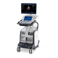
GE Vivid E90 Manuals
Manuals and User Guides for GE Vivid E90. We have
2
GE Vivid E90 manuals available for free PDF download: Service Manual, Technical Publication
GE Vivid E90 Service Manual (382 pages)
Brand:
GE
| Category:
Medical Equipment
| Size: 7.51 MB
Table of Contents
Certified Electrical Contractor Statement - for USA Only
17
Damage in Transportation
17
Omission and Errors
18
Service Safety Considerations
19
Legal Notes
20
Copyrights
21
Trademarks
21
Table of Contents
23
Chapter 1 - Introduction
31
Introduction
31
VIVID E80/E90/E95 Models Covered by this Manual
32
Product Description
33
Important Conventions
34
Conventions Used in Book
34
Standard Hazard Icons
36
Product Icons
37
Safety Considerations
38
Introduction
38
Human Safety
38
Mechanical Safety
41
Electrical Safety
44
Dangerous Procedure Warnings
46
Lockout/Tagout (LOTO) Requirements
47
Returning Probes and Repair Parts
48
Electromagnetic Compatibility (EMC)
49
What Is EMC
49
Compliance
49
Electrostatic Discharge (ESD) Prevention
50
Customer Assistance
51
Contact Information
51
Phone Numbers for Customer Assistance
52
System Manufacturer
53
Chapter 2 - Site Preparations
55
General Ultrasound System Requirements
56
Ultrasound System Environmental Requirements
56
Electrical Requirements
58
EMI Limitations
61
EMI Prevention/Abatement
62
Probes Environmental Requirements
63
Facility Needs
64
Purchaser Responsibilities
64
Required Facility Needs
66
Desirable Features
67
Minimal Floor Plan Suggestion
67
Recommended Floor Plan Suggestion
68
Suggested Floor Plan, Ultrasound System, and Echopac PC in same Room
69
Environmental Dangers
72
Patient Vicinity UL60601-1 (USA)
72
Patient Environment IEC60601-1 (IEC60601-1-1) and ANSI AAMI
73
Es60601-1
73
Chapter 3 - System Setup
75
Setup Reminders
76
Setup Warnings
76
Receiving and Unpacking the Equipment
78
Warnings for Receiving and Unpacking
78
The Tilt and Shock Indicators
79
Receiving the VIVID E80/E90/E95
82
Unpacking the VIVID E80/E90/E95
85
Packing Materials - Recycling Information
89
Preparing for Setup
91
Verify Customer Order
91
Physical Inspection
91
EMI Protection
91
Completing the Setup
92
System Specifications
92
Electrical Specifications
93
Connections on the I/O Rear Panel
94
Connections on the Patient I/O Panel
95
Connecting Probes
96
Configuration
99
VIVID E80/E90/E95 Configuration
99
Service Screen Setup
106
Optional Peripherals/Peripheral Connection
109
Software Options Configuration
111
Connectivity Overview
113
Physical Connection
113
Connectivity Setup
115
Compatibility
115
Select TCP/IP Screen
116
Changing the AE Title And/Or Port Number (Port No.)
117
DHCP Setup
118
Set the Remote Archive's Network Information
121
Save the New Settings
123
Product Locator Installation Card
124
Chapter 4 - General Procedures and Functional Checks
125
General Procedures
126
Power On/Boot up
126
Power Shut down
129
Complete Power down
131
Creating Presets
132
Functional Checks
133
2D Mode (B Mode) Checks
133
M Mode Checks
137
Color Mode Checks
141
PW/CW Doppler Mode Checks
145
Tissue Velocity Imaging (TVI) Checks
149
Probe/Connectors Checks
153
ECG Check
154
Cineloop Check
155
Back End Processor Checks
156
Operating Panel Test
157
Peripheral Checks
157
Mechanical Functions Checks
159
Chapter 5 - Components and Functions (Theory)
161
Software Overview
162
System Software
162
Application Software
162
Insite Exc
163
Introduction
163
Insite Exc Icon
163
Insite Exc Status
164
Insite Exc Definitions
165
Initiating a Request for Service (RFS)
166
Exiting Insite Exc
169
VIVID E80/E90/E95 Overview
170
Introduction
170
Note Regarding USB Ports
170
Related Information
170
VIVID E80/E90/E95 Block Diagram
171
Signal Flow Overview
172
System Configuration and Software
172
Operating Panel
172
The Electronics
172
Operating Modes
173
Top Console Description
174
Operating Panel (Control Panel)
174
Key Illumination
180
Main Console
181
Main Console Description
181
Air Flow Control
182
Air Flow Components
182
Software Control
182
Location
183
Casters and Brakes
184
Casters and Brakes Description
184
Front End Processor (FEP)
185
Front End Card Rack General Description
185
Transmitter Board (GTX)
185
Relay Board (GRLY)
188
CRX Board
190
Front Plane Boards (XD BUS)
192
Csound Power Module (CPM)
193
Back End Processor (BEP)
194
Introduction
194
Signal Flow and Processing
194
Location of the Back End Processor (BEP)
194
BEP Description
194
Bep's Side Connectors
195
Bep's Top Connectors
196
Bep's Rear Connectors
196
Inside the BEP
196
Leds
197
BEP Power Supply
198
Graphics Adapters
198
Internal Storage Devices
198
Power Distribution
199
Main Power Supply
199
Csound Power Module (CPM)
202
Input and Output (I/O) Modules
203
Patient I/O (Physio)
203
BEP I/O Board
205
Restart VIVID E80/E90/E95 after Diagnostics
206
Chapter 6 - Service Adjustments
207
LCD Monitor Adjustments
208
Cautions and Warnings
208
LCD Backlight Adjustment
209
Chapter 7 - Diagnostics/Troubleshooting
211
Service Safety Considerations
212
Gathering Troubleshooting Data
213
Purpose of this Section
213
Collect Vital System Information
213
Collect a 'Trouble Image' with Logs
214
Screen Captures
216
Purpose of this Section
216
Ctrl+Printscreen Shortcut
216
Capture a Screen Image Using the Shortcut
217
Troubleshooting
218
XY Lock Is Not Working
218
Related Information
218
XY Brake Motors Troubleshooting
218
Z Movement Fails
218
Motor Controller Test
220
Chapter 8 - Replacement Procedures
223
Warnings and Important Information
224
Warnings
224
Returning/Shipping Probes and Repair Parts
225
Manpower - When Two Persons Are Needed
227
Tools Needed for Servicing VIVID E80/E90/E95
227
Loading the Software
229
Loading the Software from Usb Flash Drive (UFD)
229
Setup after Software Loading
230
Replacing Covers and Bumpers
231
Side Covers Replacement
231
Top Cover Replacement
233
Foot Rest Bumper Replacement
236
Front Cover Replacement
238
Plate Connectors W /Guide Replacement
241
Filter Cover and Filter Replacement
243
Rear Cover Replacement
245
Rear Bumper Replacement
247
Rear Handle Replacement
249
LCD Monitor and LCD Arm Parts Replacement
251
Replacing the 19" LCD Monitor Assembly
251
Replacing the LCD Arm Assembly
253
LCD Z-Lock Replacement
255
Upper OP Panel/Touch Panel Assembly Replacement
257
Read and Follow
257
Preparations
257
Remove the Upper OP Panel/Touch Panel Assembly
258
Install the Upper OP Panel/Touch Panel Assembly
258
Verification
259
Lower Operating Panel Parts Replacement
260
Knobs for Encoders and Slidepots Replacement
260
Replacing the Operating Panel, Lower
261
Replacing the Trackball
264
A/N Keyboard Parts Replacement
267
Replacing the Alpha-Numeric (A/N) Keyboard Assembly
267
Wagon an Drawer Sheet Met. Assembly Replacement
270
Other Top Console Parts Replacement
273
Replacing the Speaker Assembly
273
Replacing the Bulkhead Board
275
Bulkhead, Plate, Extended Replacement
276
Handle, Left Top / Handle Right Top, Replacement
278
Palm Rest ASSY Replacement
280
Up-Down Button Board (Buttons Frame UI Assy) Replacement
281
Button if Board Assy Replacement
283
Replacing XYZ Parts
285
XY Mechanism Replacement
285
Z-Mechanism Replacement
287
XYZ Control Assembly Replacement
289
Main Console Parts Replacement
291
Fan Assembly Replacement
291
Main Cable Replacement
292
Casters and Brakes Replacement
295
Rear Casters Replacement
295
Front Casters Replacement
298
Pedal Mechanism Replacement
301
Brake Pedal Replacement
305
Pedal Release Replacement
305
Pedal dir Lock Replacement
306
Front End Processor (FEP) / Card Cage Parts Replacement
307
Front End Parts Overview
307
Front End Cover Replacement
308
Relay Board (RLY) Replacement
310
Transmitter Board (GTX) Replacement
313
Csound Receiver Board (CRX) Replacement
315
Csound Power Module (CPM) Replacement
317
Back End Processor (BEP) Parts Replacement
318
Back End Processor (BEP) Replacement
319
Hard Disk Drive (HDD) Replacement
323
Main Power Supply Replacement
327
Preparations
327
Main Power Supply Removal Procedure
327
Main Power Supply Installation Procedure
327
Patient I/O Assembly Replacement
329
Read and Follow
329
Preparations
329
Patient I/O Module Removal Procedure
329
Patient I/O Installation Procedure
330
Verification
330
Peripherals Replacement
331
DVD R/W Drive Replacement
331
Black & White Digital Graphic Printer Replacement
332
Cables Replacement
334
Twinax Pcie Cable Replacement
334
Chapter 9 - Renewal Parts
340
Software for VIVID E80/E90/E95
340
Covers and Bumpers
341
Top Console Parts
345
Main Monitor and LCD Arm Parts
345
Operating Panel (OP) Parts
347
Alphanumeric (AN) Keyboard Parts
348
Speaker and Bulkhead Parts
349
XYZ Parts
350
Main Console Parts
351
Casters (Wheels) Parts
352
Front End Processor (FEP) Card Rack Parts
353
Back End Processor (BEP) Parts
354
Main Power Supply
355
I/O Modules Parts
356
Peripherals for Use with VIVID E80/E90/E95
357
DVD Drive
357
Internal Printer
357
External Printers
358
Digital Video Stream Recorder (External)
358
3D Monitor - External
359
Mains Power Cables - VIVID E80/E90
360
Internal Cables - VIVID E80/E90/E95
362
ECG Cables - VIVID E80/E90/E95
364
Physio TX Parts
366
Probes for VIVID E80/E90/E95
367
Phased Array Sector Probes
367
Linear Array Probes
367
Curved Array (Convex) Probes
368
Doppler Probes
368
Transesophageal Phased Array Probes
369
Intra-Operative Probes
369
Options - VIVID E80/E90/E95
370
Chapter 10 - Care and Maintenance
371
Overview
372
Periodic Maintenance Inspections
372
Why Do Maintenance
373
Quality Assurance
373
Maintenance Task Schedule
374
How Often Should Maintenance Tasks be Performed
374
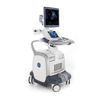
GE Vivid E90 Technical Publication (127 pages)
Ultrasound System
Brand:
GE
| Category:
Medical Equipment
| Size: 3.71 MB
Table of Contents
Table of Contents
21
Chapter 1 - Overview
25
Content in this Manual
26
Product Description
27
Overview of the Ultrasound System
27
Products Covered in this Manual
28
Chapter 2 - Safety Information
29
Overview
30
Contents in this Chapter
30
Important Conventions
31
Conventions Used in Book
31
Standard Hazard Icons
33
Product Icons
35
Label Icon Description
35
How to Lock the Operator Panel Prior to Transport
35
Safety Considerations
36
Introduction
36
Human Safety
36
Mechanical Safety
39
Electrical Safety
44
Label Locations
46
Product Labels
46
Dangerous Procedure Warnings
47
Warnings
47
Lockout/Tagout (LOTO)
48
LOTO Requirements
48
Returning Probes and Repair Parts
49
Requirements for Returning Parts
49
User Responsibility
49
Electromagnetic Compatibility (EMC)
50
What Is EMC
50
Compliance
50
Electrostatic Discharge (ESD) Prevention
51
Chapter 3 - Site Preparations
53
Overview
54
Contents in this Chapter
54
General Ultrasound System Requirements
55
Contents in this Section
55
Ultrasound System Environmental Requirements
55
Electrical Requirements
57
EMI Limitations
70
Probes Environmental Requirements
72
Time and Manpower Requirements
72
Facility Needs
73
Contents in this Section
73
Purchaser Responsibilities
73
Required Facility Needs
75
Desirable Features
77
Care and Maintenance
79
Contents in this Chapter
80
Chapter 4 - Care and Maintenance
81
Warnings
81
Why Do Maintenance
82
Keeping Records
82
Quality Assurance
82
Maintenance Task Schedule
83
How Often Should Maintenance Tasks be Performed
83
System Maintenance
84
Preliminary Checks
84
Functional Checks
85
Physical Inspection
87
Cleaning
89
Probe Maintenance
90
Using a Phantom
91
Phantoms
91
Electrical Safety Tests
92
Content in this Section
92
Uninterrupted Power Supply (UPS)
93
Safety Test Overview
94
Leakage Current Limits
97
Outlet Test - Wiring Arrangement - USA and Canada
101
Grounding Continuity
102
Chassis Leakage Current Test
103
Isolated Patient Lead (Source) Leakage-Lead to Ground
107
Isolated Patient Lead (Source) Leakage-Lead to Lead
109
Isolated Patient Lead (Sink) Leakage-Isolation Test
111
Probe (Source) Leakage Current Test
113
Isolated Probe (Sink) Leakage-Isolation Test
118
When There's too Much Leakage Current
122
AC/DC Fails
122
Chassis Fails
122
Probe Fails
123
Peripheral Fails
123
Still Fails
123
New Ultrasound System
123
ECG Fails
123
Ultrasound Equipment Quality Check (EQC and IQC)
124
Quality Checks
124
Related Products
GE Vivid E95
GE enFlow IV
GE Vivid E7
GE LOGIQ e R5 Series
GE EchoPac Workstation
GE Voluson E8
GE Voluson e BT07
GE Voluson e BT09
GE Voluson e CC200
GE LOGIQ E10
GE Categories
Refrigerator
Ranges
Microwave Oven
Air Conditioner
Dishwasher
More GE Manuals