beautypg.com
Manuals
Brands
Emerson Manuals
Controller
Unidrive SPM
Emerson Unidrive SPM Manuals
Manuals and User Guides for Emerson Unidrive SPM. We have
1
Emerson Unidrive SPM manual available for free PDF download: User Manual
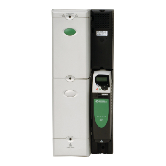
Emerson Unidrive SPM User Manual (303 pages)
variable speed AC drive
Brand:
Emerson
| Category:
Controller
| Size: 30.39 MB
Table of Contents
Table of Contents
4
Declaration of Conformity
6
1 Safety Information
7
Warnings, Cautions and Notes
7
Electrical Safety - General Warning
7
System Design and Safety of Personnel
7
Environmental Limits
7
Compliance with Regulations
7
Motor
7
Adjusting Parameters
7
Rectifier (SPMC/U)
8
Figure 2-1 Single Half Controlled Scr/Thyristor
8
Figure 2-2 Dual Half Controlled Scr/Thyristor
8
Figure 2-3 Single Diode Rectifier
8
SPMA Inverter
9
Figure 2-4 Dual Diode Rectifier
9
Figure 2-5 SPMA Inverter Schematic
9
SPMD Inverter
10
Input Line Reactor
10
Output Sharing Choke
10
Figure 2-6 SPMA Inverter Schematic
10
Figure 2-7 Single Input Line Reactor (Inlx0X)/Force Cooled (INLX0XW)
10
Figure 2-8 Dual Input Line Reactor (INLX1X)
10
Figure 2-9 Single Output Sharing Choke (OTLX0X)
10
Figure 2-10 Dual Output Sharing Choke (OTLX1X)
10
Model Number
11
Figure 2-11 Rectifier (SPMC and SPMU)
11
Figure 2-12 Drives (SPMA and SPMD)
11
Figure 2-13 Input Line Reactor / Output Sharing Choke
11
3 Product Information
12
Ratings
12
Table 3-1 SPMA 400V Drive Ratings (380V to 480V ±10%)
13
Table 3-2 Paralleled SPMA 400V Motor Drive Ratings (380V to 480V ±10%)
13
Table 3-3 SPMA 690V Drive Ratings (500V to 690V ±10%)
13
Table 3-4 Paralleled SPMA 690V Motor Drive Ratings (500V to 690V ±10%)
14
Table 3-5 SPMD 200V Drive Ratings (200V to 240V ±10%) Based on AC Supply Voltage
14
Table 3-6 Paralleled SPMD 200V Motor Drive Ratings (200V to 240V ±10%) Based on AC Supply Voltage
14
Table 3-7 SPMD 400V Motor Drive Ratings (380V to 480V ±10%) Based on AC Supply Voltage
15
Table 3-8 Paralleled SPMD 400V Motor Drive Ratings (380V to 480V ±10%) Based on AC Supply Voltage
15
Table 3-9 SPMD 690V Motor Drive Ratings (500V to 690V ±10%)
15
Table 3-10 Paralleled SPMD 690V Motor Drive Ratings (500V to 690V ±10%) Based on AC Supply Voltage
16
Table 3-11 Unidrive SPMC/U 400V Ratings
16
Table 3-12 Unidrive SPMC/U 690V Ratings
16
Table 3-13 Typical Overload Limits for All Unidrive SPM Modules
16
Operating Modes
17
Compatible Encoders
17
Table 3-14 Encoders Compatible with Unidrive SPM
17
Features
18
Figure 3-1 Features of the Unidrive SPM Modules
18
Nameplate Description
19
Figure 3-2 Typical Drive Rating Labels
19
Options
20
Figure 3-3 Control Options Available with Unidrive SPM
20
Figure 3-4 Power Options Available for Unidrive SPM
21
Table 3-15 Solutions Module Identification
21
Table 3-16 Keypad Identification
23
Table 3-17 Other Options
23
Items Supplied with the Drive
24
Table 3-18 Accessories Supplied with Unidrive SPM
24
4 System Configuration
25
Figure 4-1 Layout for a Unidrive SPMA Module Operating on a 3-Phase AC Supply
25
Figure 4-2 Layout for Two or more Unidrive SPMA Modules Operating on a 3-Phase AC Supply
26
Figure 4-3 Layout for an Unidrive SPMD Module Operating on a 3-Phase Supply
27
Figure 4-4 Layout for an Unidrive SPMD Module Operating on a 3 Phase Supply with SPMU (Uncontrolled) Rectifier and Softstart Circuit
28
Figure 4-5 Layout for Two or more Unidrive SPMD Modules Operating on a 3-Phase AC Supply
29
Figure 4-6 Layout for Two Unidrive SPMD Modules with a Dual SPMC Rectifier Operating on a 3-Phase AC Supply
30
Figure 4-7 Layout for Two Unidrive SPMD Slave Modules with a Dual SPMC Rectifier Operating on a 3-Phase AC Supply with a Remote Mounted Control Master Pod
31
Figure 4-8 Parallel Control Connections
32
5 Mechanical Installation
33
Safety Information
33
Planning the Installation
33
Terminal Cover Removal
33
Figure 5-1 Location and Identification of Terminal Covers
34
Figure 5-2 Removing the Terminal Covers
35
Figure 5-3 Removing the Unidrive SPMC/U Dual Rectifier Terminal Covers and Housing
35
Figure 5-4 Removing the Finger-Guard Break-Outs
36
Figure 5-5 Unidrive SPM Finger-Guard Grommets
36
Solutions Module Installation/Removal
37
Figure 5-6 Installation and Removal of a Solutions Module
37
Figure 5-7 Installation and Removal of a Keypad
37
Mounting of Control Master/Slave Pod
38
Figure 5-8 Mounting the Control Master Pod on the Drive
38
Figure 5-9 Mounting the Control Slave Pod on the Drive
38
Figure 5-10 Control Master/Slave Pod and Power Module Base Plate Connectors
38
Docking a Unidrive SPMC/U to an SPMD
39
Figure 5-11 Control Master Pod Dimensions
39
Figure 5-12 Docking Kit
39
Figure 5-13 Location of the Docking Kit When Installed
40
Mounting Methods
41
Figure 5-14 Surface Mounting the Unidrive SPMA
41
Figure 5-15 Surface Mounting the Unidrive SPMD
42
Figure 5-16 Surface Mounting the Unidrive SPMC/U
42
Figure 5-17 Surface Mounting the Unidrive SPMD with SPMC/U (Rectifier) and Docking Kit
43
Figure 5-18 Through-Panel Mounting the Unidrive SPMA
44
Figure 5-19 Through-Panel Mounting the Unidrive SPMD
45
Figure 5-20 Through-Panel Mounting the Unidrive SPMC/U (Rectifier)
45
Figure 5-21 Through-Panel Mounting the Unidrive SPMD with SPMC/U (Rectifier) and Docking Kit
46
Figure 5-22 Unidrive SPM Mounting Bracket
47
Figure 5-23 Orientation of the Unidrive SPM Mounting Bracket
47
Figure 5-24 Location of Top Unidrive SPMA Surface Mounting Brackets
47
Figure 5-25 Installation of the Unidrive SPMC/U Surface Mounting Brackets
47
Table 5-1 Mounting Brackets
47
Figure 5-26 Installation of the Unidrive SPMC/U through Panel Mounting Brackets
48
Enclosure
49
Figure 5-27 Enclosure Layout
49
Figure 5-28 Alternative Enclosure Layout: Undocked Unidrive SPMD and SPMC
50
Figure 5-29 Altitude Derate Factor
51
Figure 5-30 Ambient Temperature Correction Factor
51
Figure 5-31 Enclosure Design Example
52
Figure 5-32 Recommended Enclosure Design
52
Figure 5-33 Recirculation Factor
53
Table 5-2 Example Data
53
Table 5-3 Unidrive SPM Air Flow Rates
53
Heatsink Fan Operation
54
Figure 5-34 Pressure Drop
54
Figure 5-35 AC Supply 400Mm Diameter Blower Performance
54
Table 5-4 Type of Fan
54
Figure 5-36 Removal of Unidrive SPMA/D Fan (Part 1)
55
Figure 5-37 Removal of Unidrive SPMA/D Fan (Part 2)
55
Figure 5-38 Removal of Unidrive SPMC/U Fan
55
Table 5-5 Unidrive SPM Fan Assembly Part Numbers
55
Enclosing Drive for High Environmental Protection
56
Figure 5-39 Example of IP54 (NEMA 12) Through-Panel Layout
56
Figure 5-40 Option 2 for Achieving IP54 (NEMA 12) Through-Panel Mounting
57
Table 5-6 Description of Fixings
57
Table 5-7 Quantity of Nylon Washers Included in the Kit
57
External EMC Filter
58
Figure 5-41 Option 3 for Achieving IP54 (NEMA 12) through Panel Mounting
58
Figure 5-42 Mounting the External EMC Filter
58
Table 5-8 Environment Considerations
58
Table 5-10 Single Drive EMC Filter Details
58
Figure 5-43 External EMC Filter
59
Table 5-11 Optional External EMC Filter Details
59
Figure 5-44 Multiple Drive EMC Filters
60
Table 5-12 EMC Filters for Multiple Drive Combinations
60
Table 5-13 Optional External EMC Filter Details
60
Line Reactor Mounting Dimensions
61
Figure 5-45 Single Input Line Reactor (INLX0X)
61
Figure 5-46 Dual Input Line Reactor (INLX1X)
61
Figure 5-47 Single Line Input Reactor Force Cooled (INLX0XW)
61
Figure 5-48 Single Output Sharing Choke (OTLX0X)
61
Figure 5-49 Dual Output Sharing Choke (OTLX1X)
61
Electrical Terminals
62
Figure 5-50 Locations of the Power and Ground Terminals on Unidrive SPM
62
Routine Maintenance
63
Table 5-14 Master/Slave Control and Relay Terminal Data
63
Table 5-15 Drive Power Terminal Data
63
Table 5-16 Optional External EMC Filter Terminal Data
63
6 Electrical Installation
64
Power Connections
65
Figure 6-1 Unidrive SPMA Power Connections
65
Figure 6-2 Unidrive SPMD & SPMC/U (Rectifier) Power Connections
65
Figure 6-3 Unidrive SPMA Ground Connections
66
Figure 6-4 Unidrive SPMD Ground Connections
66
Figure 6-5 Unidrive SPMC/U Ground Connections
66
AC Supply Requirements
67
Figure 6-6 Unidrive SPMD and SPMC/U (Rectifier) Ground Connections
67
Figure 6-7 Input Line Reactor/Output Sharing Choke Dimensions
67
Table 6-1 Behaviour of the Drive in the Event of a Ground (Earth) Fault with an IT Supply
67
Table 6-2 400V Input Line Reactor Ratings
68
Table 6-3 400V Dual Input Line Reactor Ratings
68
Table 6-4 690V Input Line Reactor Ratings
68
Table 6-5 690V Dual Input Line Reactor Ratings
68
Output Sharing Choke Specification
69
Table 6-6 400V Output Sharing Choke Ratings
69
Table 6-7 600V Output Sharing Choke Ratings
69
Table 6-8 400V Dual Output Sharing Choke Ratings
69
Table 6-9 600V Dual Output Sharing Choke Ratings
69
Supplying the Drive with DC / DC Bus Paralleling
70
Resistor Sizing for Unidrive SPMU Softstart
70
Figure 6-8 Softstart Circuit Configuration
70
Figure 6-9 Switching Sequence for K1 and K2
70
Table 6-10 DC Bus Capacitance and Peak Supply Current Values
71
Figure 6-10 Example of Resistor Overload Characteristic
72
Figure 6-11 Example of Tripping Characteristic
72
Table 6-11 Available Resistors
72
Table 6-12 Allowable Softstart Resistor Range
72
Table 6-13 Mcbs Available from Control Techniques
72
Heatsink Fan Supply
73
Control 24Vdc Supply
73
Low Voltage DC Power Supply
73
Figure 6-12 Location of the Heatsink Fan Supply Connections (SPMA & SPMD)
73
Figure 6-13 Heatsink Fan Supply Connections (SPMA & SPMD)
73
Ratings
74
Table 6-14 Supply Fault Current Used to Calculate Maximum Input Currents
74
Table 6-15 Unidrive SPMA Input Current, Fuse and Cable Size Ratings
74
Table 6-16 Unidrive SPMD Input Current, Fuse and Cable Size Ratings
74
Table 6-17 Unidrive SPMC/U 400V Input Current, Fuse and Cable Size Rating
74
Output Circuit and Motor Protection
75
Table 6-18 Unidrive SPMC/U 690V Input Current, Fuse and Cable Size Ratings
75
Figure 6-14 Cable Construction Influencing the Capacitance
76
Figure 6-15 Preferred Chain Connection for Multiple Motors
76
Braking
77
Figure 6-16 Alternative Connection for Multiple Motors
77
Table 6-21 Braking Transistor Turn on Voltage
77
Figure 6-17 Typical Protection Circuit for a Braking Resistor
78
Table 6-22 Minimum Resistance Values and Peak Power
78
Ground Leakage
79
EMC (Electromagnetic Compatibility)
79
Figure 6-18 Installation of Grounding Bracket
79
Figure 6-19 Removal of Internal EMC Filter
80
Figure 6-20 General EMC Enclosure Layout Showing Ground Connections
81
Figure 6-21 Drive Cable Clearances
82
Figure 6-22 Feedback Cable, Twisted Pair
83
Figure 6-23 Feedback Cable Connections
83
Table 6-23 Second Environment Emission Compliance
83
Figure 6-24 Supply and Ground Cable Clearance
84
Figure 6-25 Sensitive Signal Circuit Clearance
84
Figure 6-26 Grounding the Drive, Motor Cable Shield and
85
Figure 6-27 Grounding the Motor Cable Shield
85
Figure 6-28 Shielding Requirements of Optional External Braking Resistor
85
Figure 6-29 Grounding of Signal Cable Shields Using the Grounding Bracket
86
Figure 6-30 Grounding of SPMC/U Signal Cables
86
Figure 6-31 Connecting the Motor Cable to a Terminal Block in the Enclosure
86
Figure 6-32 Connecting the Motor Cable to an Isolator
86
SPMC/U Control Connections
87
Figure 6-33 Surge Suppression for Digital and Unipolar Inputs and Outputs
87
Figure 6-34 Surge Suppression for Analog and Bipolar Inputs and Outputs
87
Figure 6-35 Location of SPMC (Rectifier) Control Terminals
87
Figure 6-36 Single Module Control Terminals and
88
Figure 6-37 Parallel Rectifier Control Terminals and
89
Low Voltage DC Mode Enable, Heatsink Fan Supply Connections (SPMA/D) and Status Input Connections (SPMD)
90
Figure 6-38 Status LED Location
90
Figure 6-39 Location of the SPMA/D Low Voltage DC Mode Enable Connections
90
Figure 6-40 SPMA Low Voltage DC Mode Enable
90
Table 6-24 Key to SPMC (Rectifier) Leds
90
Table 6-25 Key to SPMU (Rectifier) Leds
90
Figure 6-41 SPMD Low Voltage DC Mode Enable
91
Serial Communications Connections
92
Control Connections - Master Interface
92
Figure 6-42 Location of the RJ45 Serial Comms Connector
92
Table 6-26 Connection Details for RJ45 Connector
92
Table 6-27 Isolated Serial Comms Lead Details
92
Table 6-28 the Unidrive SPM Control Connections Consist of
92
Figure 6-43 Default Terminal Functions
93
Encoder Connections
96
Figure 6-44 Location of Encoder Connector
96
Table 6-29 Encoder Types
96
Table 6-30 Drive Encoder Connector Details
97
Table 6-31 Feedback Resolution Based on Frequency and Voltage Level
98
Safe Torque off (Secure Disable)
99
Figure 6-45 Start / Stop Control EN954-1 Category B - Replacement of Contactor
100
Figure 6-46 Category 3 Interlock Using Electromechanical
100
Figure 6-47 Category 3 Interlock Using SAFE TORQUE
100
Figure 6-48 Use of Contactor and Relay to Avoid the Need for Protected Wiring
100
7 Getting Started
101
Understanding the Display
101
Keypad Operation
101
Figure 7-1 SM-Keypad
101
Figure 7-2 SM-Keypad Plus
101
Menu Structure
102
Figure 7-3 Display Modes
102
Figure 7-4 Mode Examples
102
Menu 0
103
Figure 7-5 Parameter Navigation
103
Figure 7-6 Menu Structure
103
Figure 7-7 Menu 0 Copying
103
Advanced Menus
104
Changing the Operating Mode
105
Saving Parameters
105
Restoring Parameter Defaults
105
Parameter Access Level and Security
106
Displaying Parameters with Non-Default Values Only
107
Displaying Destination Parameters Only
107
Serial Communications
107
8 Basic Parameters
109
Single Line Descriptions
109
Figure 8-1 Menu 0 Logic Diagram
112
Full Descriptions
114
Figure 8-2 Fixed and Variable V/F Characteristics
116
9 Running the Motor
124
Quick Start Connections
124
Changing the Operating Mode
124
Changing Keypad Mode
124
Figure 9-1 Minimum Connections to Get the Motor Running in any Operating Mode
126
Quick Start Commissioning/Start-Up
128
Quick Start Commissioning/Start-Up (Ctsoft)
132
Setting up a Feedback Device
132
Unidrive SPM User Guide Issue Number
133
Motor Map Parameters
136
Maximum Motor Rated Current
146
Current Limits
146
Motor Thermal Protection
146
Figure 10-1 Motor Thermal Protection (Heavy Duty)
146
Figure 10-2 Motor Thermal Protection (Normal Duty)
146
Switching Frequency
147
High Speed Operation
147
Figure 10-3 Torque and Rated Voltage against Speed
147
Table 10-1 Available Switching Frequencies
147
Table 10-2 Sample Rates for Various Control Tasks at each Switching Frequency
147
11 SMARTCARD Operation
149
Figure 11-1 Installation of the SMARTCARD
149
Figure 11-2 Basic SMARTCARD Operation
149
Transferring Data
150
Table 11-1 SMARTCARD Data Blocks
150
Table 11-2 SMARTCARD Codes
150
Data Block Header Information
152
SMARTCARD Parameters
152
Table 11-3 Key to Parameter Table Coding
152
SMARTCARD Trips
153
Table 11-4 Trip Conditions
153
Table 11-5 SMARTCARD Status Indications
154
12 Onboard PLC
155
Onboard PLC and Syptlite
155
Benefits
155
Limitations
155
Figure 12-1 Onboard PLC Program Scheduling
155
Getting Started
156
Onboard PLC Parameters
156
Figure 12-2 Programming Options for Unidrive SP
156
Onboard PLC Trips
157
Onboard PLC and the SMARTCARD
157
13 Advanced Parameters
158
Table 13-1 Menu Descriptions
158
Table 13-2 Key to Parameter Table Coding
158
Table 13-3 Feature Look-Up Table
159
Table 13-4 Definition of Parameter Ranges & Variable Maximums
162
Table 13-5 Maximum Motor Rated Current
164
Menu 1: Frequency / Speed Reference
166
Figure 13-1 Menu 1 Logic Diagram
166
Menu 2: Ramps
170
Figure 13-2 Menu 2 Logic Diagram
170
Menu 3: Frequency Slaving, Speed Feedback and Speed Control
173
Figure 13-3 Menu 3 Open-Loop Logic Diagram
173
Figure 13-4 Menu 3 Closed Loop Logic Diagram
174
Menu 4: Torque and Current Control
178
Figure 13-5 Menu 4 Open Loop Logic Diagram
178
Figure 13-6 Menu 4 Closed-Loop Vector Logic Diagram
179
Figure 13-7 Menu 4 Servo Logic Diagram
180
Menu 5: Motor Control
182
Figure 13-8 Menu 5 Open-Loop Logic Diagram
182
Figure 13-9 Menu 5 Closed-Loop Logic Diagram
184
Menu 6: Sequencer and Clock
187
Figure 13-10 Menu 6 Logic Diagram
187
Menu 7: Analog I/O
189
Figure 13-11 Menu 7 Logic Diagram
189
Menu 8: Digital I/O
192
Figure 13-12 Menu 8 Logic Diagram
192
Menu 9: Programmable Logic, Motorized Pot, Binary Sum and Timers
195
Figure 13-13 Menu 9 Logic Diagram: Programmable Logic
195
Figure 13-14 Menu 9 Logic Diagram: Motorized Pot and Binary Sum
196
Menu 10: Status and Trips
198
Menu 11: General Drive Set-Up
199
Menu 12: Threshold Detectors, Variable Selectors and Brake Control Function
200
Figure 13-15 Menu 12 Logic Diagram
200
Figure 13-16 Menu 12 Logic Diagram (Continued)
201
Figure 13-17 Open-Loop Brake Function
202
Figure 13-18 Open-Loop Brake Sequence
202
Figure 13-19 Closed-Loop Brake Function
203
Figure 13-20 Closed-Loop Brake Sequence
203
Menu 13: Position Control
206
Figure 13-21 Menu 13 Open-Loop Logic Diagram
206
Figure 13-22 Menu 13 Closed-Loop Logic Diagram
208
Menu 14: User PID Controller
212
Figure 13-23 Menu 14 Logic Diagram
212
Menus 15, 16 and 17: Solutions Module Set-Up
215
Figure 13-24 Location of Solutions Module Slots and Their Corresponding Menu Numbers
215
Figure 13-25 SM-Universal Encoder Plus Logic Diagram
216
Figure 13-26 SM-Resolver Logic Diagram
220
Figure 13-27 SM-Encoder Plus Logic Diagram
222
Figure 13-28 SM-Encoder Output Plus Logic Diagram
224
Figure 13-29 SM-I/O Plus Analog Logic Diagram
227
Figure 13-30 SM-I/O Plus Digital Logic Diagram 1
228
Figure 13-31 SM-I/O Plus Digital Logic Diagram 2
229
Figure 13-32 SM-I/O Lite & SM-I/O Timer Digital I/O Logic
231
Figure 13-33 SM-I/O Lite & SM-I/O Timer Analog I/O Logic
232
Figure 13-34 SM-I/O Timer Real Time Clock Logic Diagram
232
Figure 13-35 SM-I/O PELV Digital I/O Logic Diagram
234
Figure 13-36 SM-I/O PELV Digital Input Logic Diagram
235
Figure 13-37 SM-I/O PELV Relay Logic Diagram
235
Figure 13-38 SM-I/O PELV Analog Input Logic Diagram
235
Figure 13-39 SM-I/O PELV Analog Output Logic Diagram
236
Figure 13-40 SM-I/O 24V Protected Digital I/O Logic
238
Figure 13-41 SM-I/O 24V Protected Digital I/O Logic
239
Figure 13-42 SM-I/O 24V Protected Relay Logic Diagram
239
Figure 13-43 SM-I/O 24V Protected Analog Output Logic
240
Figure 13-44 SM-I/O 120V Digital Input Logic Diagram
241
Figure 13-45 SM-I/O 120V Relay Diagram
242
Figure 13-46 SM-SLM Logic Diagram
248
Menu 18: Application Menu 1
251
Menu 19: Application Menu 2
251
Menu 20: Application Menu 3
251
Menu 21: Second Motor Parameters
252
Menu 22: Additional Menu 0 Set-Up
253
Advanced Features
254
Table 13-7 Active Reference
254
Figure 13-47 Digital Input Connections When Pr 6.04 Is
260
14 Technical Data
263
Drive
263
Table 14-6 Losses @ 40°C (104°F) Ambient
265
Table 14-7 Losses @ 40°C (104°F) Ambient (SPMD Drives in Undocked Condition)
265
Table 14-8 Losses @ 50°C (122°F) Ambient (SPMD Drives in Docked Condition)
266
Table 14-9 Losses @ 50°C (122°F) Ambient (SPMD Drives in Undocked Condition)
266
Table 14-10 Unidrive SPMC/U Losses @ 40/50°C (104/122°F) Ambient
266
Table 14-11 Power Losses from the Front of the Drive When Through-Panel Mounted
266
Table 14-12 Input Line Reactor Losses @ 40/50°C (104/122°F) Ambient
267
Table 14-13 Output Sharing Choke Losses @ 40/50°C (104/122°F) Ambient
267
Table 14-14 IP Rating Degrees of Protection
268
Table 14-15 NEMA Enclosure Ratings
268
Table 14-16 Acoustic Noise
268
Table 14-17 Overall Drive Dimensions
269
Table 14-18 Overall Drive Weights
269
Table 14-19 Supply Fault Current Used to Calculate Maximum Input Currents
269
Table 14-20 Unidrive SPMA Input Current, Fuse and Cable Size Ratings
269
Table 14-21 Unidrive SPMD Input Current, Fuse and Cable Size Ratings
269
Table 14-22 Unidrive SPMC/U 400V Input Current, Fuse and Cable Size Rating
270
Table 14-23 Unidrive SPMC/U 690V Input Current, Fuse and Cable Size Ratings
270
Table 14-24 400V Input Line Reactor Ratings
270
Table 14-25 400V Dual Input Line Reactor Ratings
270
Table 14-26 690V Input Line Reactor Ratings
270
Table 14-27 690V Dual Input Line Reactor Ratings
270
Table 6-19 Maximum Motor Cable Lengths (Unidrive SPMA)
271
Table 6-20 Maximum Motor Cable Lengths (Unidrive SPMD)
271
Table 14-28 400V Output Sharing Choke Ratings
271
Table 14-29 600V Output Sharing Choke Ratings
271
Table 14-30 400V Dual Output Sharing Choke Ratings
271
Table 14-31 600V Dual Output Sharing Choke Ratings
271
Table 14-32 Maximum Motor Cable Lengths
271
Table 14-33 Maximum Motor Cable Lengths
271
Table 14-34 Minimum Resistance Values and Peak Power Rating for the Braking Resistor at 40°C (104°F)
272
Table 14-35 Master Drive Control and Relay Terminal Data
272
Table 14-36 Drive Power Terminal Data
272
Table 14-37 Immunity Compliance
272
Optional External EMC Filters
273
Table 14-38 SPMA (400V Only) Emission Compliance
273
Table 14-39 SPMA (690V Only) Emission Compliance
273
Table 14-1 Maximum Permissible Continuous Output Table 14-40 SPMD (400V Only) Emission Compliance
273
Table 14-42 Unidrive SPM and EMC Filter Cross Reference
273
Table 14-2 Maximum Permissible Continuous Output Table 14-43 EMC Filters for Multiple Drive Combinations
273
Table 14-45 Optional External EMC Filter Dimensions
274
Table 14-3 Maximum Permissible Continuous Output Table 14-46 Optional External EMC Filter Terminal Data
274
Trip Indications
275
Figure 15-1 Keypad Status Modes
275
Figure 15-2 Location of the Status LED
275
Table 15-2 Serial Communications Look-Up Table
290
Table 14-4 Maximum Permissible Continuous Output Table 15-3 Trip Categories
291
Alarm Indications
292
Status Indications
292
Table 15-5 Status Indications
292
Displaying the Trip History
293
Behaviour of the Drive When Tripped
293
16 UL Listing Information
294
Common UL Information
294
Power Dependant UL Information
294
AC Supply Specification
294
Maximum Continuous Output Current
294
Safety Label
294
UL Listed Accessories
294
List of Figures
295
List of Tables
297
Index
299
Related Products
Emerson unidrive sp
Emerson unidrive m
Emerson unidrive hs modular
Emerson Unidrive 72
Emerson uerdant VX Series
Emerson Universal-R
Emerson UM380
Emerson UHA1R-0050L
Emerson Klauke UAP332CFM
Emerson Sensi UP500W
Emerson Categories
Controller
Control Unit
Transmitter
Measuring Instruments
Fan
More Emerson Manuals