Table of Contents
Save these instructions for future use!
FAILURE TO READ AND FOLLOW ALL INSTRUCTIONS
CAREFULLY BEFORE INSTALLING OR OPERATING THIS
CONTROL COULD CAUSE PERSONAL INJURY AND/OR
PROPERTY DAMAGE.
THERMOSTAT APPLICATION GUIDE
Configuration Options
Gas, Oil, Electric, Heat Only,
Cool Only or Heat/Cool
Systems, 2 or 3 wire Hydronic
Zone (Hot Water or Steam)
Systems, 24 Volt or Millivolt
Single Stage Compressor
Heat Pump Systems - up to 2
Heat Pump (HP1)
Stages Aux./Emergency Heat
Heat Pump 2
Two Stage or Two Compressor
Two Stage or Two
Compressor Heat Pump
Stages Aux./Emergency Heat
Electrical Rating:
Battery Power . . . . . . . . . . . . . . . . . . . . . . . . . . mV to 30 VAC, NEC Class II, 50/60 Hz or DC
Input-Hardwire . . . . . . . . . . . . . . . . . . . . . . . . . 20 to 30 VAC
Terminal Load . . . . . . . . . . . . . . . . . . . . . . . . . . . . . 1.5A per terminal, 2.5A maximum all terminals combined
Setpoint Range . . . . . . . . . . . . . . . . . . . . . . . . . . . . 45 to 99°F (7 to 37°C)
Rated Differentials:
Heat (Single Stage/Multi-Stage) . . . . . . . . . . . .
Cool (Single Stage/Multi-Stage) . . . . . . . . . . . .
Heat Pump . . . . . . . . . . . . . . . . . . . . . . . . . . . .
Emer Heat . . . . . . . . . . . . . . . . . . . . . . . . . . . .
Operating Ambient. . . . . . . . . . . . . . . . . . . . . . . . . . 32°F to +105°F (0 to +41°C)
Operating Humidity . . . . . . . . . . . . . . . . . . . . . . . . . 90% non-condensing max.
Shipping Temperature Range . . . . . . . . . . . . . . . . . -40 to +150°F (-40 to +65°C)
Dimensions Thermostat. . . . . . . . . . . . . . . . . . . . . . 4-9/16"H x 5-13/16"W x 1-3/16"D
Humidity Setpoint Range . . . . . . . . . . . . . . . . . . . . . 5 to 50%
Dehumidification Setpoint Range . . . . . . . . . . . . . . 40 to 95%
CAUTION
!
To prevent electrical shock and/or equipment damage,
disconnect electric power to system at main fuse or
circuit breaker box until installation is complete.
Index
Installation
Maximum
Thermostat
Stages
Applications
Heat/Cool
1+1
2+2
3+1
4+2
Page
2
3
5
6
10
12
15
www.white-rodgers.com
www.emersonclimate.com
Big Blue Humidity Universal Thermostat
with Humidity/Dehumidity Control and
Automatic Heat/Cool Changeover Option
Single Stage, Multi-Stage, Heat Pump
Installation and Operating Instructions
Model
1F95-1291
7 Day
1F95-1291 Humidity Control Touchscreen Thermostat
Fast.
Slow
0.6°F
1.5°F
1.2°F
1.7°F
1.2°F
1.7°F
0.6°F
1.7°F
ATTENTION: MERCURY NOTICE
This product does not contain mercury. However, this prod-
uct may replace a product that contains mercury.
Mercury and products containing mercury must not be
discarded in household trash. Do not touch any spilled
mercury. Wearing non-absorbent gloves, clean up any
spilled mercury and place in a sealed container. For proper
disposal of a product containing mercury or a sealed
container of spilled mercury, place it in a suitable shipping
container. Refer to www.thermostat-recycle.org for loca-
tion to send the product containing mercury.
Programming Choices
5+1+1 Day
Non-Programmable
APPLICATIONS
SPECIFICATIONS
PART NO. 37-7313B
Replaces 37-7313A
1241
Table of Contents

Related Manuals for Emerson 1F95-1291


Summary of Contents for Emerson 1F95-1291
-
Page 1: Table Of Contents
Programming Choices CAREFULLY BEFORE INSTALLING OR OPERATING THIS CONTROL COULD CAUSE PERSONAL INJURY AND/OR 1F95-1291 7 Day 5+1+1 Day Non-Programmable PROPERTY DAMAGE. APPLICATIONS 1F95-1291 Humidity Control Touchscreen Thermostat THERMOSTAT APPLICATION GUIDE Maximum Thermostat Thermostat Stages Configuration Options Applications Heat/Cool Gas, Oil, Electric, Heat Only,... -
Page 2: Thermostat
7. Carefully line the thermostat up with the base and snap into place. Figure 1 – Thermostat Base Multi-Stage 1F95-1291 Battery Location 2 "AA" alkaline batteries are included in the thermostat at the factory with a battery tag to prevent power drainage. Remove the battery tag to engage the batteries. -
Page 3: No Heat Pump (Ss1)
Original production heating if configured Cool mode-1st Heat mode-1st Multi Stage 2 Cool mode-2nd Heat mode-2nd & Off mode. Set for remote for Electric Heat) 1F95-1291’s stage stage stage stage (MS2) to “B” terminal sensor) do not have this energized in connection Heat &... - Page 4 WIRING DIAGRAMS Figure 4 – Humidity and Sensors De-energizes on call for Humidification Terminal, Supply voltage Supply voltage Remote Dehumidification to Energizes on call for to remote to remote temperature lower the fan speed. heat if Humidity setpoint temperature temperature sensor signal The DHM terminal is is above room humidity.
-
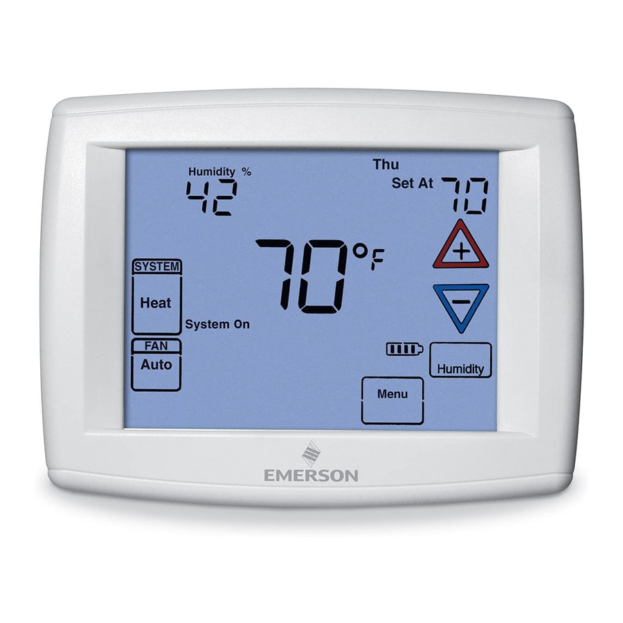
Page 5: Thermostat Quick Reference
THERMOSTAT QUICK REFERENCE Home Screen Description Figure 8 – Home Screen Display Room Temperature Day of Week Set Temperature/Humidity Time of Day Note: If is displayed, the Temperature thermostat is battery powered. UP/Down used for System When battery power remaining modifying setpoint Switch is approximately half,... -
Page 6: Installer Configuration Menu
INSTALLER/CONFIGURATION MENU To enter the menu: Press the Menu touch key. Press and hold for 5 seconds the Installer Config touch key. This displays screen reference #1 in the table below. Screen Reference numbers appear in top right corner of display. Press to advance to the next menu item or to return to a previous menu item. - Page 7 INSTALLER/CONFIGURATION MENU CONFIGURATION MENU Screen Displayed Press Press Option Reference Factory Comments to select from Selected Number (Default) listed options (35) dF -5 - 50 Selects Dual Fuel setpoint (°F), dF selected On with outdoor sen- sor available. (05) dF 0 - 09 Selects Dual Fuel setpoint (°F), dF selected On with no outdoor ...
- Page 8 INSTALLER/CONFIGURATION MENU a time delay built in and do not require this feature to be humidity allowing a slightly higher temperature to feel activated in the thermostat. Your compressor manufactur- comfortable. As the peak load subsides, this feature also er can tell you if this lockout feature is already present in takes advantage of the air conditioner's increased capacity their system.
- Page 9 INSTALLER/CONFIGURATION MENU Skip this step and continue through the remainder of the pump system versus your auxiliary system relative to the configuration menu if you require an Air Filter Change thermostat adjustment. The higher the number the sooner out indicator or Humidifier Pad Change out indicator by the auxiliary stage energizes for better comfort.
-
Page 10: Operating Your Thermostat
INSTALLER/CONFIGURATION MENU “HM” terminal) if the actual humidity is below the humid- again. This dehumidification feature may use more energy ity set point. The display indicates AH. Pressing the by making dehumidification a priority initiating a call for key will cycle the display from OFF to H (feature enabled cooling if humidity is 2% above desired setting. -
Page 11: Emergency Mode
OPERATING YOUR THERMOSTAT Emergency Mode Fan On selection runs the fan continuously for increased air circulation or to allow additional air cleaning. Applies only to Heat Pump Systems Tip: Running the fan more frequently will increase your Emergency Heat (System EM Position) bypasses the Heat energy consumption. -
Page 12: Programming
PROGRAMMING Set Current Time and Day Fill in the blank schedule on the next page then: Enter the Heating Program 1. Press Menu key to enter installer menu. Then press Set Time once to indicate hour & AM or PM designation 1. - Page 13 Energy Saving Factory Pre-Program The 1F95-1291 thermostats are programmed with the energy saving settings shown in the table below for all days of the week. If this program suits your needs, simply set the thermostat clock and press the RUN key.
-
Page 14: Wired Remote Temperature Sensing
PROGRAMMING Worksheet for Re-Programming 5+1+1 and 7 Day Program Heating Wake Up Leave For Work Return Home Go To Bed Program (Morning) (Day) (Evening) (Night) 6:00 AM 70°F Auto 8:00 AM 62°F Auto 5:00 PM 70°F Auto 10:00 PM 62°F Auto 6:00 AM 70°F... -
Page 15: Troubleshooting
PROGRAMMING Averaging or Weighting Remote Sensors Dual Fuel Temperature Setpoint The thermostat will weight or average the temperature of the When the thermostat is configured for Heat Pump mode and indoor remote sensor with the local sensor in the thermostat the Dual Fuel feature is selected on, the thermostat can moni- for each program period. - Page 16 Thermostat does not have 1. Earlier version of thermostat To access the earlier version instruction sheet (37-6914E) Menu Screen Numbers go to www.white-rodgers.com, enter 1F95-1291 in Model Number Search HOMEOWNER HELP LINE: 1-800-284-2925 White-Rodgers is a business of Emerson Electric Co.