Quick Links
Save these instructions for future use!
FAILURE TO READ AND FOLLOW ALL INSTRUCTIONS
CAREFULLY BEFORE INSTALLING OR OPERATING THIS
CONTROL COULD CAUSE PERSONAL INJURY AND/OR
PROPERTY DAMAGE.
THERMOSTAT APPLICATION GUIDE
Description
Heat Pump (No Aux. or Emergency Heat)
Heat Pump (with Aux. or Emergency Heat)
Systems with up to 4 Stages Heat, 2 Stages Cool
Heat Only Systems
Millivolt Heat Only Systems - Floor or Wall Furnaces
Cool Only Systems
Gas or Oil Heat
Electric Furnace
Hydronic (Hot Water) Zone Heat - 2 Wires
Hydronic (Hot Water) Zone Heat - 3 Wires
Wired Remote Temperature Sensor (Indoor or Outdoor)
Dual Fuel Feature (Heat Pump Mode, Outdoor Remote
Required) or Damper Control Feature
Electrical Rating:
Battery Power . . . . . . . . . . . . . . . . . . . . . . . . . . mV to 30 VAC, NEC Class II, 50/60 Hz or DC
Input-Hardwire . . . . . . . . . . . . . . . . . . . . . . . . . 20 to 30 VAC
Terminal Load . . . . . . . . . . . . . . . . . . . . . . . . . . . . . 1.5A per terminal, 2.5A maximum all terminals combined
Setpoint Range . . . . . . . . . . . . . . . . . . . . . . . . . . . . 45 to 99°F (7 to 32°C)
Differential (Single Stage) . . . . . . . . . . . . . . . . . . . . Heat 0.6°F; Cool 1.2°F
Differential (Multi-Stage) . . . . . . . . . . . . . . . . . . . . . Heat 0.6°F; Cool 1.2°F
Differential (Heat Pump) . . . . . . . . . . . . . . . . . . . . . Heat 1.2°F; Cool 1.2°F
Operating Ambient. . . . . . . . . . . . . . . . . . . . . . . . . . 32°F to +105°F (0 to +41°C)
Operating Humidity . . . . . . . . . . . . . . . . . . . . . . . . . 90% non-condensing max.
Shipping Temperature Range . . . . . . . . . . . . . . . . . -40 to +150°F (-40 to +65°C)
Dimensions Thermostat. . . . . . . . . . . . . . . . . . . . . . 4.2"H x 6.4"W x 1.7"D
CAUTION
!
To prevent electrical shock and/or equipment damage,
disconnect electric power to system at main fuse or
circuit breaker box until installation is complete.
Index
Blue Commercial Thermostat with
Automatic Heat/Cool Changeover
Option and Damper Control
Single Stage, Multi-Stage, Heat Pump
Installation and Operating Instructions for Model:
Model
1F95-0680
1F95-0680 Commercial Thermostat
Yes
Yes
Yes
Yes
Yes
Yes
Yes
Yes
Yes
Yes
Yes
Yes
ATTENTION: MERCURY NOTICE
This product does not contain mercury. However, this prod-
uct may replace a product that contains mercury.
Mercury and products containing mercury must not be
Page
discarded in household trash. Do not touch any spilled
2
mercury. Wearing non-absorbent gloves, clean up any
3
spilled mercury and place in a sealed container. For proper
5
disposal of a product containing mercury or a sealed
6
container of spilled mercury, place it in a suitable shipping
9
container. Refer to www.thermostat-recycle.org for loca-
10
tion to send product containing mercury.
14
www.white-rodgers.com
www.emersonclimate.com
Programming Choices
7 Day
5/1/1 Day
Non-Programmable
APPLICATIONS
SPECIFICATIONS
PART NO. 37-6819B
Replaces 37-6819A
1345

Related Manuals for Emerson White Rodgers 1F95-0680


Summary of Contents for Emerson White Rodgers 1F95-0680
-
Page 1: Table Of Contents
Blue Commercial Thermostat with Automatic Heat/Cool Changeover Option and Damper Control Single Stage, Multi-Stage, Heat Pump Save these instructions for future use! Installation and Operating Instructions for Model: FAILURE TO READ AND FOLLOW ALL INSTRUCTIONS Model Programming Choices CAREFULLY BEFORE INSTALLING OR OPERATING THIS CONTROL COULD CAUSE PERSONAL INJURY AND/OR 1F95-0680 7 Day... -
Page 2: Installation
INSTALLATION Power Stealing Switch WARNING The Power Stealing Switches (Figure 1, rear view) should be left in the "On" position for most systems. The information in Thermostat installation and all components of the the following table details the thermostat power method and control system shall conform to Class II circuits per switch options. -
Page 3: Wiring Diagrams
WIRING DIAGRAMS Refer to equipment manufacturers' instructions for specific Wiring diagrams shown are for typical systems and describe system wiring information. After wiring, see CONFIGURA- the thermostat terminal functions. TION section for proper thermostat configuration. TERMINAL DESIGNATION DESCRIPTIONS Terminal Designation Description O/B ....Changeover valve for heat pump energized constantly in cooling and off/heating Y2 ....2nd Stage Compressor... - Page 4 WIRING DIAGRAMS Figure 4 – Heat Pump Systems Jumper System Heat Mode - 2nd Heat Mode - 3rd Stage, Emergency Stage, Emergency Mode - 1st Stage Mode - 2nd Stage Blower/ Time of Heat Pump 1 Energized in Note: Dual Fuel option Note: Dual Fuel option Circulator Fan Day/...
-
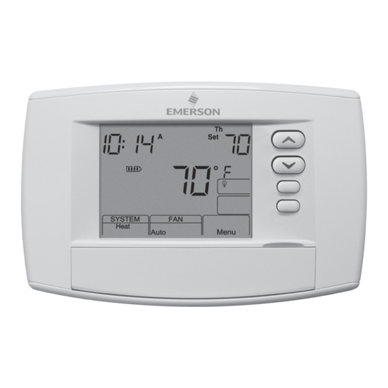
Page 5: Thermostat Quick Reference
THERMOSTAT QUICK REFERENCE Home Screen Description Figure 5 – Home Screen Display Room Setting Temperature Temperature Battery Level Indicator Indicating the current power level of the 2 “AA” batteries: Full power remaining. Half power remaining Change The batteries should be replaced at this time with 2 new premium brand “AA”... -
Page 6: Installer Configuration Menu
INSTALLER/CONFIGURATION MENU Thermostat must be in Heat, Cool or Auto. Press and hold the Menu button for at least 5 seconds. The display will show item #1 in the table below. Press Menu to advance to the next menu item. Press to change a menu item options. - Page 7 INSTALLER/CONFIGURATION MENU 21 19 MENU (OFF) L, P, Limit Selects one of 3 Keypad Lockout configurations Keypad Lockout L - Total Keypad Lockout P - Partial Keypad Lockout (Up and Keys still work) Limit - Limited Temperature Range MENU (000) 1-999 Selects personal lockout code.
- Page 8 INSTALLER/CONFIGURATION MENU 5°. Allowing 5 minutes per degree, the thermostat setpoint in Heat or Cool mode, select desired setpoint temperature will change to 70° at 6:35 AM. Cooling allows more time and press Auto Schedule. This value will be copied into per degree, because it takes longer to reach set tempera- all the morning, day and evening program periods.
-
Page 9: Operating Your Thermostat
INSTALLER/CONFIGURATION MENU purge time the A1 terminal will also be energized. button. 29) Select Filter Replacement Reminder and Set Run Time 25) Select Compressor Off (CO) Feature Using Outdoor Select the "Change Filter" reminder On or OFF. If se- Sensor – This feature is applicable only in heat pump lected On, press MENU to select the time period from 25 modes and with an outdoor sensor installed and enabled. -
Page 10: Programming
OPERATING YOUR THERMOSTAT Emergency System Choose the System Setting (Cool, Off, Heat, Em, Auto) EM bypasses the Heat Pump to use the heat source wired to terminal W/E on the thermostat. EM is typically used when Press the SYSTEM button to select: compressor operation is not desired, or you prefer back-up Heat: Thermostat controls only the heating system. - Page 11 PROGRAMMING Energy Saving Factory Pre-Program The 1F95-0680 thermostats are programmed with the energy saving settings shown in the table below for all days of the week. If this program suits your needs, simply set the thermostat clock and press the RunSched button. The table below shows the factory set heating and cooling schedule for all days of the week.
- Page 12 PROGRAMMING Automatic Daylight Saving Calculation Enter the Cooling Program The Real Time Clock will adjust automatically for daylight sav- 1) Press the SYSTEM button until the Cool icon appears. 2) Follow Enter Heating Program instructions for entering ings time, in the following manner: Increment one hour at 2 AM on the second Sunday of March cooling times and temperatures.
- Page 13 PROGRAMMING Wired Remote Temperature Sensing The example shows that the weight selected would prioritize the overall averaged temperature between the two sensors. One remote temperature sensor can be installed indoor or The high weight selection caused the remote sensor to have outdoor and connected to the thermostat by a maximum a higher influence in the calculated temperature average than cable length of 100 meters (300 feet).
-
Page 14: Troubleshooting
TROUBLESHOOTING Reset Operation Note: When thermostat is reset, installer configuration menu settings and programming will reset to factory settings. If a voltage spike or static discharge blanks out the display or causes erratic thermostat operation, you can reset the thermo- stat by removing the wires from terminals R and C (do not short them together) and removing batteries for 2 minutes. - Page 15 NOTES...
- Page 16 HOMEOWNER HELP LINE: 1-800-284-2925 White-Rodgers is a business of Emerson Electric Co. The Emerson logo is a www.white-rodgers.com trademark and service mark www.emersonclimate.com of Emerson Electric Co.