Emerson 1F83-0471 Operating Instructions Manual
Blue 4” universal thermostat with automatic heat/cool changeover option
Hide thumbs
Also See for 1F83-0471:
- Installation and operating instructions manual (8 pages) ,
- Information sheet (2 pages)
Table of Contents
Save these instructions for future use!
FAILURE TO READ AND FOLLOW ALL INSTRUCTIONS
CAREFULLY BEFORE INSTALLING OR OPERATING
THIS CONTROL COULD CAUSE PERSONAL INJURY
AND/OR PROPERTY DAMAGE.
APPLICATIONS
THERMOSTAT APPLICATION GUIDE
Description
Heat Pump (No Aux. or Emergency Heat)
Heat Pump (with Aux. or Emergency Heat)
Systems with up to 2 Stages Heat, 2 Stages Cool
Heat Only Systems (with optional fan switch)
Millivolt Heat Only Systems – Floor or Wall Furnaces
Cool Only Systems
Gas or Oil Heat
Electric Furnace
Hydronic (Hot Water) Zone Heat – 2 Wires
Hydronic (Hot Water) Zone Heat – 3 Wires
Compressor with Comfort Alert II Module (1F85CA only)
SPECIFICATIONS
Electrical Rating:
Battery Power .................................................... mV to 30 VAC, NEC Class II, 50/60 Hz or DC
Input-Hardwire ................................................... 20 to 30 VAC
Terminal Load ........................................................... 1.5 A per terminal, 2.5A maximum all terminals combined
Setpoint Range ......................................................... 45° to 90°F (7° to 32°C)
Rated Differentials:
Heat (Single Stage/Multi Stage) ........................ 0.4 °F
Cool (Single Stage/Multi Stage) ........................ 0.9 °F
Heat Pump ......................................................... 0.9 °F
Aux. Heat ........................................................... 0.6 °F
Operating Ambient .................................................... 32° to +105°F (0° to +41°C)
Operating Humidity ................................................... 90% non-condensing max.
Shipping Temperature Range ................................... -40° to +150°F (-40° to +65°C)
Dimensions Thermostat ............................................ 3-7/8"H x 5-1/8"W x 1-1/4"D
CAUTION
!
To prevent electrical shock and/or equipment damage,
disconnect electric power to system at main fuse or
circuit breaker box until installation is complete.
Index
Installation
Wiring Connections
Wiring Diagrams
Thermostat Quick Reference
Installer Configuration Menu
Operating Your Thermostat
Troubleshooting
Blue 4" Universal Thermostat with
Automatic Heat/Cool Changeover Option
Single Stage, Multi-Stage or Heat Pump
Installation and Operating Instructions for Model:
Model
1F83-0471
Yes
Yes
Yes
Yes
Yes
Yes
Yes
Yes
Yes
Yes
Yes
Fast
Med.
0.6 °F
1.2 °F
1.2 °F
–
ATTENTION: MERCURY NOTICE
This product does not contain mercury. However, this product
may replace a product that contains mercury.
Mercury and products containing mercury must not be
discarded in household trash. Do not touch any spilled
Page
mercury. Wearing non-absorbent gloves, clean up any
spilled mercury and place in a sealed container. For proper
2
disposal of a product containing mercury or a sealed
2
container of spilled mercury, place it in a suitable shipping
3
container. Refer to www.white-rodgers.com for location to
4
send product containing mercury.
5
7
7
www.white-rodgers.com
www.emersonclimate.com
Programming Choice
Non-Programmable
1F83-0471 Thermostat
Slow
1.7 °F
1.7 °F
1.7 °F
1.7 °F
PART NO. 37-7237A
1
1117
Table of Contents

Related Manuals for Emerson 1F83-0471


Summary of Contents for Emerson 1F83-0471
-
Page 1: Specifications
Blue 4” Universal Thermostat with Automatic Heat/Cool Changeover Option Single Stage, Multi-Stage or Heat Pump Installation and Operating Instructions for Model: Save these instructions for future use! Model Programming Choice FAILURE TO READ AND FOLLOW ALL INSTRUCTIONS CAREFULLY BEFORE INSTALLING OR OPERATING 1F83-0471 Non-Programmable THIS CONTROL COULD CAUSE PERSONAL INJURY... -
Page 2: Remove Old Thermostat
INSTALLATION Figure 1 – Battery door shown open WARNING Thermostat installation and all components of the control system shall conform to Class II circuits per “AA” Alkaline Batteries the NEC code. Remove Old Thermostat A standard heat/cool thermostat consists of three basic parts: Thermostat can be powered by system AC power or Battery. -
Page 3: Wiring Diagrams
WIRING DIAGRAMS Heat Pump Connections HEAT PUMP TYPE 1 (HP 1). Single stage compressor If you do not have a heat pump system, refer to figures 4-6. system; gas or electric backup. Refer to equipment manufacturers’ instructions for specific HEAT PUMP TYPE 2 (HP 2). Multi-stage compressor or two system wiring information. -
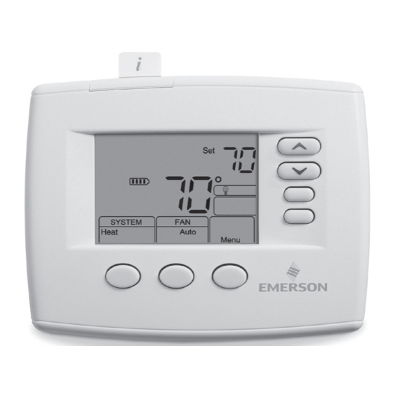
Page 4: Home Screen Display
THERMOSTAT QUICK REFERENCE Home Screen Description Figure 7 – Home Screen Display Room Setting Temperature Temperature Displays the power level of the 2 “AA” batteries: indicates good power level indicates batteries at about half power. “Change ” indicates batteries are low and should be replaced with 2 new premium brand SYSTEM “AA”... -
Page 5: Installer/Configuration Menu
INSTALLER/CONFIGURATION MENU To enter the Configuration Menu, SYSTEM must be set to HEAT, COOL or EMER. Press the Menu button for at least 5 seconds. The display will show item #1 in the table below. Press Menu button to advance to the next menu item. Press to change a menu item. - Page 6 INSTALLER/CONFIGURATION MENU 1 & 2)Keypad Lockout – This menu selection will display If “Save” is not displayed and this feature is OFF, no “Lk” and “OFF” (default, keypad not locked out). The change will occur when the cooling system is continu- are used to toggle the selection between ously running during periods of high demand.
-
Page 7: Troubleshooting
INSTALLER/CONFIGURATION MENU 19) Comfort Alert with Active Protection – Turn this period from 25 to 1975 hours in 25 hours increments. feature ON to enable active protection. This allows the In a typical system, 200 hours (default) of run time is thermostat to identify fault codes sent by the Comfort approximately 30 days. - Page 8 1. Earlier version of thermostat. Refer to Instruction Sheet 37-7149B Menu Screen Numbers HOMEOWNER HELP LINE: 1-800-284-2925 White-Rodgers is a division of Emerson Electric Co. The Emerson logo is a www.white-rodgers.com trademark and service mark of Emerson Electric Co. www.emersonclimate.com...
- Page 9 Electric Emerson servicio www.white-rodgers.com marca comercial marca Emerson logotipo Electric Emerson división White-Rodgers 1-800-284-2925 USUARIO: PARA AYUDA LÍNEA menu pantalla numerous 37-7149B. manual Refiérase termostato. anterior Version tiene termostato restablecerá. teclado bloqueo bloqueo segundos durante MENU botón Presione código Olvidó...
- Page 10 voltaje Bajo parpadeos comodidad. alerta módulo soldado Contactor parpadeos amarillo junto parpadea técnico), servicio abierto funcionamiento Circuito parpadeos (Llamar Service” “Call mensaje muestra comodidad alerta abierto inicio Circuito parpadeos compatible termostato comodidad. termostato-alerta abierto Circuito parpadeos interfaz módulo termostato transmitidos intermitentes códigos comodidad.
- Page 11 demanda. alta períodos durante continua forma funcionando esté enfriamiento sistema cuando cambios realizarán disminuye. referencia temperatura cuando controles mismos OFF, está función esta “Save” palabra aparece proporciona Cool) rápido frío función minutos. seleccionado. ajuste rango dentro diez más durante real temperatura encima más...
- Page 12 terminal como (O/B) inversora válvula terminal Heat Cool salida funcionamiento Selecciona MENÚ anterior. opción (activado) seleccionado aparece sólo menú Este horas. incrementos filtro Cambiar filtro cambio frecuencia Ajusta 25-1975 (200 MENÚ (desactivado). (activado) filtro) Cambio (indicador filtro Cambiar ...
- Page 13 termostato. 37-7149B. manual falla indica calefacción/enfriamiento. sistema require anterior modelo termostato blanco, falla indica técnico) servicio (llamar Service” “Call pantalla. numero indica configuracion, menu menú. bloqueado. esta teclado cuando "LOC" Parpadea Savings Cool opción activado Cool modo está cuando enfriamiento) (ahorro Savings”...
- Page 14 CLASE TRANSFORMADOR VIVO NEUTRO etapa sola frío calor (neutro) (vivo) cables energizado circulador (vivo) Válvula Válvula voltios voltios zonificadas Soplador/Ventilador voltios Constante Abre Cierra válvulas Aplicación Sistema Puente (SPDT) cables solamente calor zonificadas válvulas Cableado – Figura CLASE TRANSFORMADOR CLASE necesario.
-
Page 15: Instalación
calor llamada cuando Energizada – cables zonificada Válvula 6....etapa segunda Compresor ..... calor sólo compresor Relé ....sistema transformador enfriamiento sistema calefacción constantemente transformador secundario lado neutro Cable ....energizada calor bomba para inversora Válvula ....enfriamiento para .....Alimentación enfriamiento constantemente calefacción... -
Page 16: Especificaciones
1117 www.emersonclimate.com www.white-rodgers.com 37-7237A PIEZA N° problemas Solución termostato usar Cómo configuración instalador/de Menú mercurio. contienen termostato rápida referencia Guía productos enviar pueden lugares indican conexiones Diagrama www.white-rodgers.com adecuado. transporte contenedor eléctricas Conexiones colóquelo derramado, mercurio sellado recipiente mercurio contiene producto adecuada forma...