Table of Contents
Quick Links
INDEX
Thermostat Installation
Wiring
Installer Menu
Using the Thermostat
Thermostat Overview
Troubleshooting
Technical Support
SPECIFICATIONS
Electrical Rating:
Input-Hardwire .................................... 20 to 30 VAC, NEC Class II, 50/60 Hz
Terminal Load .......................................... 1.5 A per terminal, 2.5A maximum all terminals combined
Setpoint Range ........................................ 60°F to 85°F (16°C to 29°C)
Rated Differentials (@ 6°F/ Hr):
Heat Pump (Heating) ........................... 0.9°F
Heat Pump (Cooling) ........................... 0.9°F
Auxiliary Heat ...................................... 0.5°F
Operating Ambient .................................. 32°F to +105°F (0° to +41°C)
Display Temperature Range ....................... 32°F to +99°F (0 to 37°C)
Operating Humidity ................................. 90% non-condensing maximum
Shipping Temperature Range ................... -20°F to + 150°F (-29° to +65°C)
Thermostat Dimensions ........................... 3-3/4" H x 6" W x 1-1/8" D
emerson.com/white-rodgers
1F75P-21NP (Non-Programmable)
2-4
Thermostat Applications
2
3-4
Single Stage Cooling, One or Two
Stage Heating
5
Electric only
5
6-7
MERCURY NOTICE: This product does not contain
mercury. However, this product may replace a product
8
that contains mercury. Mercury and products containing
mercury must not be discarded in household trash.
Refer to www.thermostat-recycle.org for information
on disposing of products containing mercury.
Fast
Med
1.2°F
1.2°F
0.75°F
Installation and Operating Instructions
Hardwired with Common
– 1 Stage Aux Heat
Slow
1.7°F
1.7°F
1.9°F
PART NO. 37-7880001
PTAC Thermostat
Maximum
Stages
Heat /Cool
2/1
2241
Table of Contents

Related Manuals for Emerson 1F75P-21NP


Summary of Contents for Emerson 1F75P-21NP
- Page 1 1F75P-21NP (Non-Programmable) Installation and Operating Instructions PTAC Thermostat Hardwired with Common INDEX Thermostat Installation Maximum Thermostat Applications Stages Wiring Heat /Cool Installer Menu Single Stage Cooling, One or Two Stage Heating – 1 Stage Aux Heat Using the Thermostat Electric only...
-
Page 2: Thermostat Installation
THERMOSTAT INSTALLATION WIRING Refer to equipment manufacturer’s instructions for specific system wiring information. After wiring, see INSTALLER MENU for proper thermostat configuration. Wiring table shown are for typical systems and describe the thermostat terminal functions. Terminal Designations Terminal Function Low Speed Fan Relay Power (24V) Changeover Terminal-Energized in Cool (O) or Heat (B) for Heat Pump. -
Page 3: Installer Menu
Jumper wire Instructions: To convert the system from PTHP to PTAC, cut the jumper wire located on the back of the thermostat. Change menu item #20 from default HP to AC. Note: Menu item #32 will not be displayed in AC mode. 1.) O/B Terminal Switch The O/B switch on this thermostat is factory set to the B position. -
Page 4: Test Equipment
TEST EQUIPMENT Turn on power to the system. Fan Operation 1.) Move fan switch to Low position. The blower should begin to operate at low speed . 2.) Move fan switch to Auto Low position. The blower should stop immediately. 3.) Move fan switch to High position. -
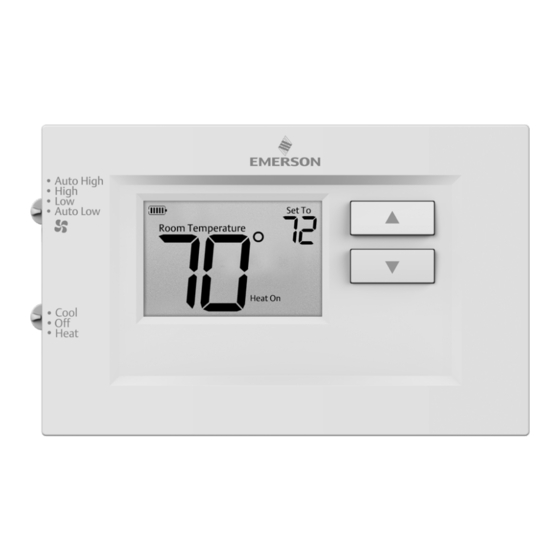
Page 5: Using The Thermostat
USING THE THERMOSTAT THERMOSTAT OVERVIEW Before you begin using your thermostat, you should be familiar with its features, display and the location/operation of the thermostat buttons and switches. THERMOSTAT BUTTONS THE DISPLAY AND SWITCHES 1.) Fan Switch 5.) Thermostat is protecting the equipment from short cycling (5-minute delay) 2.) System Switch 6.) Indicates that the system is running in cool, heat or auxiliary... -
Page 6: Troubleshooting
TROUBLESHOOTING Symptom Possible Cause Corrective Action 1.) Blown fuse or tripped circuit 1.) Replace fuse or reset breaker breaker 2.) Furnace power switch to OFF No Heat/ 2.) Turn switch to ON No Cool/ 3.) Furnace blower compartment 3.) Replace door panel in proper position to No Fan door panel loose or not properly engage safety interlock or door switch... - Page 7 TROUBLESHOOTING (C0ntinued) Symptom Possible Cause Corrective Action Furnace (Air Digital thermostats provide precise control and Conditioner) cycle faster than older mechanical models. The Cycles Too Fast or system turns on and off more frequently, but runs The location of the thermostat and/or Slow (narrow or for a shorter time.
- Page 8 TECHNICAL SUPPORT: 1-888-725-9797...