Table of Contents
Quick Links
Programming
made Simple
See page 7
INDEX
Thermostat Installation
Wiring
Installer Menu
Test Equipment
Using the Thermostat
Thermostat Overview
Thermostat Operation
Thermostat Schedule/Programming
Troubleshooting
Homeowner Help Line
SPECIFICATIONS
Electrical Rating:
Battery Power ..................................... 20 to 30 VAC, NEC Class II, 50/60 Hz
Input-Hardwire .................................... 20 to 30 VAC, NEC Class II, 50/60 Hz
Terminal Load .......................................... 1.5 A per terminal, 2.5A maximum all terminals combined
Setpoint Range ........................................ 45° to 99° F (7° to 37° C)
Rated Differentials (@ 6°F/ Hr): Fast .Med Slow
Heat Pump (Heat)................................ 0.9°F
Heat Pump (Cool) ................................ 0.9°F
Auxiliary Heat ...................................... 0.5°F
Operating Ambient .................................. 32°F to +105°F (0° to +41°C)
Display Temperature Range ....................... 32°F to +99°F (0 to 37°C)
Operating Humidity ................................. 90% non-condensing maximum
Shipping Temperature Range ................... -20°F to + 150°F (-29° to +65°C)
Thermostat Dimensions ........................... 3-3/4" H x 6" W x 1-1/8" D
emerson.com/white-rodgers
Installation and Operating Instructions
Battery Powered or Hardwired with Common
Optional Accessory: Wall
Cover-Up Plate F61-2663,
6 3/4" W x 4 1/2" H
2-4
Thermostat Applications
2
3-4
Single Stage Compressor, Heat Pump
Systems (air source or geothermal) –
4
1 Stage Aux/Emergency Heat, Electric
5-7
or Gas (Dual Fuel)
5
MERCURY NOTICE: This product does not contain
6
mercury. However, this product may replace a product
6-7
that contains mercury. Mercury and products containing
mercury must not be discarded in household trash.
7-8
Refer to www.thermostat-recycle.org for information
on disposing of products containing mercury.
8
1.2°F
1.2°F
0.75°F
1F75H-21PR (Programmable)
Heat Pump Thermostat
1.7°F
1.7°F
1.9°F
PART NO. 37-7843001
Maximum
Stages
Heat/ Cool
2/1
2102
Table of Contents

Related Manuals for Emerson 1F75H-21PR


Summary of Contents for Emerson 1F75H-21PR
- Page 1 1F75H-21PR (Programmable) Installation and Operating Instructions Heat Pump Thermostat Battery Powered or Hardwired with Common Programming made Simple See page 7 Optional Accessory: Wall Cover-Up Plate F61-2663, 6 3/4” W x 4 1/2” H INDEX Thermostat Installation Maximum Thermostat Applications...
-
Page 2: Thermostat Installation
THERMOSTAT INSTALLATION WIRING Refer to equipment manufacturer’s instructions for specific system wiring information. After wiring, see INSTALLER MENU for proper thermostat configuration. Wiring table shown are for typical systems and describe the thermostat terminal functions. Terminal Designations Terminal Function Power (24V) Changeover Terminal-Energized in Cool (O) or Heat (B) for Heat Pump or Damper Systems Heat and Cool Mode 1st Stage Compressor... -
Page 3: Installer Menu
Battery Location Premium AA alkaline batteries are required when C-wire is not available. When C-wire is available, the batteries provide a back-up source of power (this will maintain the clock in the event of a power outage). 1.) W2/E Jumper Wire This thermostat electrically connect the W2 and E terminals so that you do not need to do this with a jumper wire. -
Page 4: Test Equipment
INSTALLER MENU (C0ntinued) Settings Installer’s Menu # Default Setting Description (flashing icons) (Hold Menu 8 Seconds) (Press °F – Fahrenheit Fahrenheit or Celsius °F °C – Celsius Temperature Display Adjustment -5 to +5 (adjust the displayed “Room Temperature”) Continuous Display Light (keep On –... -
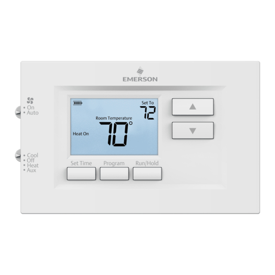
Page 5: Using The Thermostat
USING THE THERMOSTAT THERMOSTAT OVERVIEW Before you begin using your thermostat, you should be familiar with its features, display and the location/operation of the thermostat buttons and switches. THERMOSTAT BUTTONS THE DISPLAY AND SWITCHES 1.) Fan Switch 9.) Thermostat is protecting the equipment from short cycling (5-minute delay) 2.) System Switch 10.) Indicates that the system is running in cool, heat or auxiliary... -
Page 6: Thermostat Operation
THERMOSTAT OPERATION Set Current Time and Day Note: Time icons will flash at initial power up or after a reset. 1.) Press Set Time 2.) Use to adjust the hour 3.) Press Next to advance to set the minutes and day of the week 4.) Press Exit when finished. -
Page 7: Troubleshooting
display. Also displayed are the currently programmed start time for the 1st heating period and the currently programmed temperature (flashing). This display window shows that for the 1st weekday period, the start time is 6:00 AM, and 70° is the programmed temperature (this example reflects factory preprogramming). 3. - Page 8 To conveniently reset only the schedule and user settings back to factory defaults, press and Set Time buttons at the same time and hold until the display goes blank and resets. HOMEOWNER HELP LINE: 1-800-284-2925 Emerson and White-Rodgers are trademarks of Emerson Electric Co. ©2021 Emerson Electric Co. All rights reserved. emerson.com/white-rodgers...