Table of Contents
Quick Links
Programming
made Simple
See page 7
INDEX
Thermostat Installation
Wiring
Installer Menu
Using the Thermostat
Thermostat Overview
Troubleshooting
Homeowner Help Line
SPECIFICATIONS
Electrical Rating:
Battery Power ..................................... 20 to 30 VAC, NEC Class II, 50/60 Hz
Input-Hardwire .................................... 20 to 30 VAC, NEC Class II, 50/60 Hz
Terminal Load .......................................... 1.5 A per terminal, 2.5A maximum all terminals combined
Setpoint Range ........................................ 45° to 99° F (7° to 37° C)
Rated Differentials (@ 6°F/ Hr):
Heat Pump (Heat)................................ 0.9°F
Heat Pump (Cool) ................................ 0.9°F
Auxiliary Heat ...................................... 0.5°F
Operating Ambient .................................. 32°F to +105°F (0° to +41°C)
Display Temperature Range ....................... 32°F to +99°F (0 to 37°C)
Operating Humidity ................................. 90% non-condensing maximum
Shipping Temperature Range ................... -20°F to + 150°F (-29° to +65°C)
Thermostat Dimensions ........................... 3-3/4" H x 6" W x 1-1/8" D
emerson.com/white-rodgers
1F75H-21NP (Non-Programmable)
Battery Powered or Hardwired with Common
Optional Accessory: Wall
Cover-Up Plate F61-2663,
2-4
Thermostat Applications
2
3-4
Single Stage Compressor, Heat Pump
Systems (air source or geothermal) –
5
1 Stage Aux/Emergency Heat
5
6-7
MERCURY NOTICE: This product does not contain
8
mercury. However, this product may replace a product
that contains mercury. Mercury and products containing
mercury must not be discarded in household trash.
Refer to www.thermostat-recycle.org for information
on disposing of products containing mercury.
Fast
Med
1.2°F
1.2°F
0.75°F
Installation and Operating Instructions
Heat Pump Thermostat
6 3/4" W x 4 1/2" H
Slow
1.7°F
1.7°F
1.9°F
PART NO. 37-7842001
Maximum
Stages
Heat /Cool
2/1
2102
Table of Contents

Related Manuals for Emerson White-Rodgers 1F75H-21NP


Summary of Contents for Emerson White-Rodgers 1F75H-21NP
- Page 1 Display Temperature Range ....... 32°F to +99°F (0 to 37°C) Operating Humidity ......... 90% non-condensing maximum Shipping Temperature Range ....-20°F to + 150°F (-29° to +65°C) Thermostat Dimensions ......3-3/4” H x 6” W x 1-1/8” D PART NO. 37-7842001 2102 emerson.com/white-rodgers...
-
Page 2: Thermostat Installation
THERMOSTAT INSTALLATION WIRING Refer to equipment manufacturer’s instructions for specific system wiring information. After wiring, see INSTALLER MENU for proper thermostat configuration. Wiring table shown are for typical systems and describe the thermostat terminal functions. Terminal Designations Terminal Function Power (24V) Changeover Terminal-Energized in Cool (O) or Heat (B) for Heat Pump or Damper Systems Heat and Cool Mode 1st Stage Compressor... -
Page 3: Installer Menu
Battery Location Premium AA alkaline batteries are required when C-wire is not available. When C-wire is available, the batteries provide a back-up source of power (this will maintain the clock in the event of a power outage). 1.) W2/E Jumper Wire This thermostat electrically connect the W2 and E terminals so that you do not need to do this with a jumper wire. -
Page 4: Test Equipment
INSTALLER MENU (C0ntinued) Settings Installer’s Menu # Default Setting Description (flashing icons) (Hold Menu 8 Seconds) (Press °F – Fahrenheit Fahrenheit or Celsius °F °C – Celsius Temperature Display Adjustment -5 to +5 (adjust the displayed “Room Temperature”) Continuous Display Light (keep On –... -
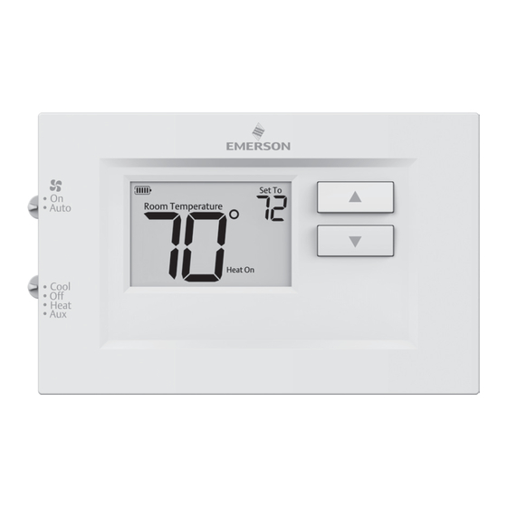
Page 5: Using The Thermostat
USING THE THERMOSTAT THERMOSTAT OVERVIEW Before you begin using your thermostat, you should be familiar with its features, display and the location/operation of the thermostat buttons and switches. THERMOSTAT BUTTONS THE DISPLAY AND SWITCHES 1.) Fan Switch 5.) Thermostat is protecting the equipment from short cycling (5-minute delay) 2.) System Switch 6.) Indicates that the system is running in cool, heat or auxiliary... -
Page 6: Troubleshooting
TROUBLESHOOTING Symptom Possible Cause Corrective Action 1.) Blown fuse or tripped circuit 1.) Replace fuse or reset breaker breaker 2.) Furnace power switch to OFF No Heat/ 2.) Turn switch to ON No Cool/ 3.) Furnace blower compartment 3.) Replace door panel in proper position to No Fan door panel loose or not properly engage safety interlock or door switch... - Page 7 TROUBLESHOOTING (C0ntinued) Symptom Possible Cause Corrective Action Digital thermostats provide precise control and Furnace (Air cycle faster than older mechanical models. The Conditioner) system turns on and off more frequently, but runs The location of the thermostat and/ Cycles Too Fast or for a shorter time.
- Page 8 HOMEOWNER HELP LINE: 1-800-284-2925 Emerson and White-Rodgers are trademarks of Emerson Electric Co. ©2021 Emerson Electric Co. All rights reserved. emerson.com/white-rodgers...