Table of Contents
Save these instructions for future use!
FAILURE TO READ AND FOLLOW ALL INSTRUCTIONS
CAREFULLY BEFORE INSTALLING OR OPERATING THIS
CONTROL COULD CAUSE PERSONAL INJURY AND/OR
PROPERTY DAMAGE.
THERMOSTAT APPLICATION GUIDE
Configuration Options
Gas, Oil, Electric, Heat Only,
Cool Only or Heat/Cool
Systems, 2 or 3 wire Hydronic
Zone (Hot Water or Steam)
Systems, 24 Volt or Millivolt
Single Stage Compressor
Heat Pump Systems - up to 2
Heat Pump (HP1)
Stages Aux./Emergency Heat
Heat Pump 2
Two Stage or Two Compressor
Two Stage or Two
Compressor Heat Pump
Stages Aux./Emergency Heat
Electrical Rating:
Battery Power . . . . . . . . . . . . . . . . . . . . . . . . . . mV to 30 VAC, NEC Class II, 50/60 Hz or DC
Input-Hardwire . . . . . . . . . . . . . . . . . . . . . . . . . 20 to 30 VAC
Terminal Load . . . . . . . . . . . . . . . . . . . . . . . . . . . . . 1.5A per terminal, 2.5A maximum all terminals combined
Setpoint Range . . . . . . . . . . . . . . . . . . . . . . . . . . . . 45 to 99°F (7 to 37°C)
Rated Differentials:
Heat (Single Stage/Multi-Stage) . . . . . . . . . . . .
Cool (Single Stage/Multi-Stage) . . . . . . . . . . . .
Heat Pump . . . . . . . . . . . . . . . . . . . . . . . . . . . .
Emer Heat . . . . . . . . . . . . . . . . . . . . . . . . . . . .
Operating Ambient. . . . . . . . . . . . . . . . . . . . . . . . . . 32°F to +105°F (0 to +41°C)
Operating Humidity . . . . . . . . . . . . . . . . . . . . . . . . . 90% non-condensing max.
Shipping Temperature Range . . . . . . . . . . . . . . . . . -40 to +150°F (-40 to +65°C)
Dimensions Thermostat. . . . . . . . . . . . . . . . . . . . . . 4-9/16"H x 5-13/16"W x 1-3/16"D
CAUTION
!
To prevent electrical shock and/or equipment damage,
disconnect electric power to system at main fuse or
circuit breaker box until installation is complete.
Index
Installation
Blue Universal Touchscreen Thermostat with
Automatic Heat/Cool Changeover Option
Maximum
Thermostat
Stages
Applications
Heat/Cool
1+1
2+2
3+1
4+2
Page
2
3
4
5
9
10
13
white-rodgers.com
emersonclimate.com
Single Stage, Multi-Stage, Heat Pump
Installation and Operating Instructions
Model
Programming Choices
1F95-1277
7 Day
5+1+1 Day
1F95-1277 Touchscreen Thermostat
Fast.
Slow
0.6°F
1.5°F
1.2°F
1.7°F
1.2°F
1.7°F
0.6°F
1.7°F
ATTENTION: MERCURY NOTICE
This product does not contain mercury. However, this
product may replace a product that contains mercury.
Mercury and products containing mercury must not be
discarded in household trash. Do not touch any spilled
mercury. Wearing non-absorbent gloves, clean up any
spilled mercury and place in a sealed container. For proper
disposal of a product containing mercury or a sealed
container of spilled mercury, place it in a suitable shipping
container. Refer to www.thermostat-recycle.org for
location to send the product containing mercury.
Non-Programmable
APPLICATIONS
SPECIFICATIONS
PART NO. 37- 6753E
Replaces 37-6753D
1517
Table of Contents

Related Manuals for Emerson 1F95-1277


Summary of Contents for Emerson 1F95-1277
-
Page 1: Table Of Contents
Programming Choices CAREFULLY BEFORE INSTALLING OR OPERATING THIS CONTROL COULD CAUSE PERSONAL INJURY AND/OR 1F95-1277 7 Day 5+1+1 Day Non-Programmable PROPERTY DAMAGE. APPLICATIONS 1F95-1277 Touchscreen Thermostat THERMOSTAT APPLICATION GUIDE Maximum Thermostat Thermostat Stages Configuration Options Applications Heat/Cool Gas, Oil, Electric, Heat Only,... -
Page 2: Thermostat
7. Carefully line the thermostat up with the base and snap into place. Figure 1 – Thermostat Base Multi-Stage 1F95-1277 Battery Location 2 "AA" alkaline batteries are included in the thermostat at the factory with a battery tag to prevent power drainage. Remove the battery tag to engage the batteries. -
Page 3: No Heat Pump (Ss1)
WIRING DIAGRAMS Figure 2 – Single Stage or Multi-Stage System (No Heat Pump) with Single Transformer System Single Stage 1 Call for cool No Output Call for heat No output Installer (SS1) Configuration Fault or System Menu selects 24 volt Malfunction “O”... -
Page 4: Thermostat Quick Reference
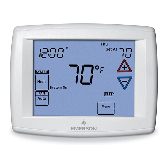
THERMOSTAT QUICK REFERENCE Home Screen Description Figure 8 – Home Screen Display Room Temperature Day of Week Set Temperature Time of Day Note: If is displayed, the Temperature thermostat is battery powered. UP/Down used for System When battery power remaining modifying setpoint Switch is approximately half,... -
Page 5: Installer Configuration Menu
INSTALLER/CONFIGURATION MENU To enter the menu: Press the Menu touch key. Press and hold for 5 seconds the Installer Config touch key. This displays screen reference #1 in the table below. Screen Reference numbers appear in top right corner of display. Press to advance to the next menu item or to return to a previous menu item. - Page 6 INSTALLER/CONFIGURATION MENU CONFIGURATION MENU Screen Displayed Press Press Option Reference Factory Comments to select from Selected Number (Default) listed options (OFF) dF Selects Dual Fuel feature On or OFF (this item appears if HP1 or HP2 is selected above). (35) dF -5 - 50 Selects Dual Fuel setpoint (°F), dF selected On with outdoor sen-...
- Page 7 INSTALLER/CONFIGURATION MENU Power Stealing Switches ON Power Stealing Switches ON Table 1 (Factory Default) (Factory Default) Backlight Option Backlight Option Backlight Option Backlight Option (Factory Default) (Factory Default) Power Method Momentary Battery Only (before thermostat installation or mV heat systems) No Backlight Momentary Backlight No Backlight Backlight...
- Page 8 INSTALLER/CONFIGURATION MENU out allows only the keys to operate within your 35. Select Dual Fuel Setting – With DF selected On and no set temperature limits. outdoor sensor, select the dF setting from 01-09. Fac- "Temperature Limit/Keypad Lockout" prevents chang- tory default is 05.
-
Page 9: Operating Your Thermostat
The cooling system should stop operating. CAUTION Choose the Fan Setting (Auto or On or Prog) There are two fan features on the 1F95-1277 Do not allow the compressor to run unless the compres- sor oil heaters have been operational for 6 hours and the 1. -
Page 10: Programming
OPERATING YOUR THERMOSTAT Manual Operation (Bypassing the Program) override the temperature setting for a (default) four hour Programmable Mode override period. The override period can be shortened by pressing or lengthened by pressing . Program Override Manual operation will bypass the program and allow you to period can range from 15 minutes to 7 days. -
Page 11: Enter The Cooling Program
PROGRAMMING Enter the Cooling Program Cooling Example: 1. In cool, press Auto Schedule once. 1. Press the SYSTEM key until the "Cool" icon appears. 2. Follow Enter Heating Program instructions for entering 2. Press to select a comfortable cooling cooling times and temperatures. temperature (example 75°). -
Page 12: Wired Remote Temperature Sensing
PROGRAMMING Worksheet for Re-Programming 5+1+1 and 7 Day Program Heating Wake Up Leave For Work Return Home Go To Bed Program (Morning) (Day) (Evening) (Night) 6:00 AM 70°F Auto 8:00 AM 62°F Auto 5:00 PM 70°F Auto 10:00 PM 62°F Auto 6:00 AM 70°F... -
Page 13: Troubleshooting
PROGRAMMING Averaging or Weighting Remote Sensors Dual Fuel Temperature Setpoint The thermostat will weight or average the temperature of the When the thermostat is configured for Heat Pump mode indoor remote sensor with the local sensor in the thermostat and the Dual Fuel feature is selected on, the thermostat can for each program period. - Page 14 To access the earlier version instruction sheet (37-6914E) Menu Screen Numbers go to www.white-rodgers.com, enter 1F95-1291 in Model Number Search HOMEOWNER HELP LINE: 1-800-284-2925 White-Rodgers is a business of Emerson Electric Co. The Emerson logo is a white-rodgers.com trademark and service mark emersonclimate.com of Emerson Electric Co.