Table of Contents
Table of Contents

Related Manuals for Jack k4 Series


Summary of Contents for Jack k4 Series
- Page 2 ’ 0 / 51...
- Page 3 1 / 51...
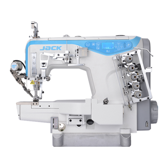
- Page 4 Operatio n panel Silicone oil reservoir Thread (Upper) guide Needle bar guard PLUG sight window Presser foot adjustment screw Thread tension Thread take-up guard Finger guard Eye guard Stitch adjustment Indication knob plate 2 / 51...
- Page 5 3 / 51...
- Page 6 Chain 1 hook Chain 2 4 / 51...
- Page 7 5 / 51...
- Page 8 6 / 51...
- Page 9 7 / 51...
- Page 10 8 / 51...
- Page 11 9 / 51...
- Page 12 10 / 51...
- Page 13 11 / 51...
- Page 14 12 / 51...
- Page 15 13 / 51...
- Page 16 14 / 51...
- Page 17 15 / 51...
- Page 18 Sewing machine adjustment Attention In order to prevent the sudden start of the machine which causing a personal accident, please turn off the power, make sure the motor does stop rotating before operating! 1 Cooler wire guide adjustment. Adjust the release needle thread guide hight to the number below then tightening screw Figure7-1 Accounting to different fabric, we can change thread taking up length by...
- Page 19 17 / 51...
- Page 20 3 Adjustment of spreader thread take up at the top point release set screw make the top of inner guide line fix to the bottom of guider slot, then tight the set screw Figure 8-3 18 / 51...
- Page 21 1 Adjustment of thread cam and thread cam guider Hit thread cam adjustment When needle at the top Figure 8-4 adjust hit thread cam make it at the position that just start hit thread. 19 / 51...
- Page 22 20 / 51...
- Page 23 screw Dividing thread plate Dividing thread plate 21 / 51...
- Page 24 22 / 51...
- Page 25 needle Needle plate 23 / 51...
- Page 26 Lowest Right end point point screw 24 / 51...
- Page 27 25 / 51...
- Page 28 on 1/3 of the right needle hole 26 / 51...
- Page 29 srew over thread 27 / 51...
- Page 30 Needle plate Screw 1 Screw 2 28 / 51...
- Page 31 Screw 2 Screw Feedd needle Needle plate 29 / 51...
- Page 32 pinpoint pinpoint pinpoint 30 / 51...
- Page 33 Front guard needle looper Front guard needle protect device Front guard needle screw 31 / 51...
- Page 34 adjust lower cutter adjust left and right positions of lower cutter 32 / 51...
- Page 35 Moving blade looper 33 / 51...
- Page 36 34 / 51...
- Page 37 The center of the looper 35 / 51...
- Page 38 the eccentric pin set screw 2 36 / 51...
- Page 39 Moving cutter 37 / 51...
- Page 40 is parallel to the fixed cutter. Moving cutter Screw1 Screw3 Screw4 Fixed cutter Screw2 38 / 51...
- Page 41 clip is parallel to the fixed cutter. Pressure sheet clip 39 / 51...
- Page 42 40 / 51...
- Page 43 41 / 51...
- Page 44 42 / 51...
- Page 45 43 / 51...
- Page 46 44 / 51...
- Page 47 45 / 51...
- Page 48 46 / 51...
- Page 49 47 / 51...
- Page 50 48 / 51...
- Page 51 49 / 51...
- Page 52 50 / 51...
- Page 54 8 8 8 8 8 8 8 8...
- Page 56 P 9 9 0/1/2 P 0 1 200~5500 4000 P 0 3 P 0 4 200~3000 1800 P 0 5 200~3000 1800 P 0 7 0~200 P 0 8 0~200 P 0 9 P 1 0 P 1 6 1~3000 P 1 7 0~99 P 2 4...
- Page 57 P 5 0 1~500 P 5 1 0~100 P 5 2 1~800 P 5 3 P 5 4 0~100 P 5 6 P 5 7 0~600 P 6 0 200~5500 4000 P 6 2 P 6 6 P 7 1 0~50 P 7 6 1~500...
- Page 58 0 1 0 0 2 5 0 2 6 0 1 1 0 1 2 0 2 7 0 2 8 0 1 3 0 2 9 0 2 0 0 2 1 0 2 A 0 2 B 0 2 2 0 2 C 0 2 3 0 3 0 - 0 3 7...
- Page 59 E r r - 0 8 E r r - 0 9 E r r - 1 0 E r r - 1 1 E r r - 1 2 E r r - 1 3 E r r - 1 4 E r r - 1 5 E r r - 1 6 E r r - 1 7...
- Page 60 K4 Operation Manual Safety Instruction Please read this manual carefully, also with related manual for the machinery before use the controller. For installing and operating the controller properly and safely, qualified engineers are required. Please stay away from arc welding equipment, in order to avoid electromagnetic interference and malfunction of the controller.
- Page 61 Fig.1-2 Controller Interface Definition 1.3 Wiring and Grounding We must prepare the system grounding project, a qualified electrical engineer is requested for the construction. Product is energized and ready for use; you must ensure that the power outlet the AC input is securely grounded. The grounding wire is yellow and green lines, it must be connected to the grid and reliable security protection on the ground to ensure safe use, and prevent abnormal situation.
- Page 62 Index mark Description Index Icon Description Icon Description Index Icon Description Index Down needle Position W bar tacking sewing(No functtion) Multi-section constant-stitch sewing(No Up needle Position functtion) Automatic trimming The bottom line counter Foot lifting at seam End One-Shot-Sewing in constant-stitch Voice reminder Foot lifting after trimming Presser foot lifting...
- Page 63 2.3 Composite keys that 3 System parameters setting list 3.1 Parameter mode 1 In the standby state ,press key to enter the parameter modes. 2 Press corresponding key and key to adjust the corresponding parameter. When the parameter values have increased and decreased, parameter interface flash. Short press key to save the modified parameters .Long press key to exit parameter interface, return to standby model.
- Page 64 Automatic induction presser foot sensor setting (between the maximum and minimum P 1 7 0~99 value of the 02C parameter display) P 2 4 0~1024 Trimming point of pedal P 2 7 Presser Foot sensor mode setting: 0: off 1: turn on only after trimming 2: always ON 0~31 P 3 0...
- Page 65 time) P 7 6 1~500 Trimming electromagnet full output time ms P 9 8 Mention voice volume (0 to 4) 4 for maximum volume changes (factory default) P 9 9 language selection 0: off, 1: Chinese, 2:English, default language 1 Chinese P A 0 1 9999 The lift foot release down Delay time after remove cloth when sensing turn on.
- Page 66 Power is off alarm Please wait for 30 seconds, then turn on the power switch Please check the trimming cutter is back the original place, after checking still safety alarm, please adjust the sensor holder, if still cannot solved, Safety switch alarm please enter P66 parameter change from 2 to 0.
- Page 67 Initial motor electrical angle - Try 2 to 3 more times after power down E r r - 1 2 failure - if it still does not work, please replace the controller and inform the manufacturer. Turn off the system power, check if the motor sensor plug is loose or dropped off, E r r - 1 3 Motor HALL failure restore it and restart the system.
- Page 124 35AC /35ACFT device...
- Page 125 35AC /35ACFT device Description Parts No. Ref.Part.No. Number...
- Page 126 35AC /35ACFT device...
- Page 127 35AC /35ACFT device...