Table of Contents
Table of Contents

Related Manuals for Jack JK-T781E Series


Summary of Contents for Jack JK-T781E Series
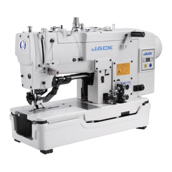
- Page 1 JK-T781E series...
- Page 2 technical parameters and models Model JK-T781E JK-T782E JK-T783E JK-T781EK Purpos (Textile, chemical fiber fabric )buttonhole`s Knitting sewing lock Buttonhole length 22mm 33mm 40mm 22mm Stitch width 2.5~4mm 2.5~5mm 2.5~5mm 2.5~4mm Cutter length 6.4~19mm 6.4~25.4mm 6.4~31.7mm 6.4~19mm (1/4”~3/4”) (1/4”~1”) (1/4”~1 1/4”) (1/4”~3/4”) Speed 100~3600rpm/min...
- Page 3 1.2 adjust needle and hook First way:see the no. of 2 in the first picture, put the ruler like this between the Needle plate and needle bar,move the position of needle bar until the distance between needle bar and the ruler is 0. Adjust the hook to make the tip of the hook from the upper end of the pinhole 1.6 ~ 1.8mm, tighten the screw of Rotary hooks to make that the distance between two Tips of the hook is about 0.05 mm.
- Page 4 2.1、adjust the needle bar height Second way:(observe the hook),Install the needle to make the needle in the middle of the pinhole, move the needle bar to the lowest point, observe and make the upper edge of the pinhole not exceed the needle plate. lowest point,of the needle...
- Page 5 2.2、adjust needle and hook Second way: 1、 Turn the handle,until the the pallet moves to the right baseline, Turn the handwheel until the needle moves to the right baseline,during the period of returning of the needle bar, adjust the Rotary tip util hooking above the pinhole,at the the lowest plat.
- Page 6 3.0、adjust buttonhole width and stitching reference position The movement of the needle is based on the right side of the needle swing. When adjusting, please follow the following steps: 1、Baseline width adjustment: Turn screw 1 and align the baseline pointer to the desired scale on the scale plate.2、Reinforce sewing width adjustment:Tighten screw 2 to align the reinforcement pointer to the baseline pointer.3、Right baseline position: twist screw 3, adjust the cutter to cut the screws when the right baseline is not cut.4、Left position of the baseline: When...
- Page 7 4.0 adjust position of feeding control panel when work finishe ◆ If the control plate position is not correct, whenever you change the sewing size, the knife will malfunction, the position of the presser foot will change, resulting in broken needle, broken thread.
- Page 8 18.0:Adjustment of the button hole length Standard:This adjustment is same as 781D serie. Method: 1. Pull out the part, put up the canning. : 2. Loose the screw, let the pointer front to the number you need. (The number should be same as length of cutter) Then tighten the screw。 Feeding Crank 781E Machine mode and Number Comparison Pointer...
- Page 9 19.0:Adjustment of the position of lower line fixed knife Adjustment stardard: the distance between fixed knife and needle plate hole is 0.3-0.5mm. Adjustment influence: if the distance between the fixed knife and the needle plate hole is too close, the thread breakage will happen when you sew. fixed knife fasten screw Adjustment method: 1.Lose the fixed knife fasten screw.
- Page 10 29.0:The sensor chip of automatic foot-lift position adjustment Adjustment standard: When the machine is in the parked position (the presser foot is in the decentralized state), the motor will automatically find the zero position, so that the mechanical lock between the starting plate and the movement pin left 3mm gap. Adjustment methods:...
- Page 11 31.0:Adjustment and functions of feeding sensor ◆The main function of feeding sensor is:prevent foot lifting during sewing, the sensor lamp goes out when entering the sewing state,press , can not lift the foot,when stop sewing, the sensor lamp lights up and presses presser , lift the presser foot ◆Easy to adjust the presser foot up and down during maintain Adjustment method;Loosen the set screws, adjust the sensor up and down, make sure...
- Page 12 三、Parameters and fault codes 1、Operation button Enter and determine the Enter the parameter content value, any stored content value changes of the value, need to press the to save confirmation. Enter the parameter area 1. In normal boot mode, press the key function key to enter the user parameter mode 2.
- Page 13 2、LED display script and actual script comparison table Digital script part: Actual value: LCD: 3、Display mode of the LCD screen English script part: English alphabet: LCD: English alphabet: LCD: English alphabet: LCD:...
- Page 14 4、Factory reset Press the up and down key and at the Press enter key Press F key and reboot same time boot the to save it machine up, it will show P11.
- Page 15 5、Enter user mode and modify & save(1-10) normal case, Press up and Press enter key to press F to get into down key to change get the value of this user parameter mode. parameter items. parameter. Press up and down Press enter key to key to modify the Press F key to get out...
- Page 16 6、Enter technician mode*(11-25) Press F key Press up and Press enter key to and at the down key to change get the value of this same time boot parameter items. parameter. the machine up Press up and down Press enter key to Press F key to get out key to modify the save the value...
- Page 17 7、System officer mode-limited to item(26-27) Press up and down Press F and Press up key to key to modify the Press F key to enter key find parameter value get out of this and at the P26 (speed and then press mode.
- Page 18 8、Manual up positioning adjustment Press up key Move the hand Press the up to find Press F key to and down key wheel to adjust P27 and the get out of this and press and at the press ENTER to mode.
- Page 19 9、user parameters item description range Initial note value P01 Max speed(rpm) 10~360 Sewing speed(actual speed=display number *10) P02 Start sewing speed 20~360 Start sewing speed(actual speed=display number*10)for 781E, it doesn’t work (rpm) P03 Cutter movement 10- 100 The rotation of head during the cutting(actual speed speed=display number*10)...
- Page 20 Initial item description range note value How many stitched protected if the big board senses Protected stitches 1 - 990 nothing Find the up position 1:Find the up position automatically after booting automatically after 0 - 1 0:function closed booting Up positioning Up positioning adjustment, value decreases means 40 - 180...
- Page 21 11、Error code Error Content Solution code Module driver efforts and head efforts are both closed. Power module error code waiting for restart(check power board)not frequent 2)Abnormal overcurrent and overvoltage Stepper motor communication Check the communication line between stepper motor drive abnormal board and main board.
- Page 22 12、Error code Power on and no positioner Automatically working in no-positioner mode, and cutting thread, inserted tangent, up positioning and all fixed needle sewing pattern sewing functions have no effect. The motor can work normally. (check positioner) Power module overheating Check the power module and cooling fin is good contact protection Encoder signal fault...