Table of Contents
Table of Contents

Related Manuals for Jack JK-T781E


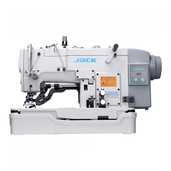
Summary of Contents for Jack JK-T781E
- Page 2 Warning: For your personal safety, when operating the kind of products, please make sure that the ground wire of power plug is connected to ground, otherwise an electric shock may occur. Safety Instruction: Users are required to read the operation manual completely and carefully before installation or operation and keep it properly for reference at any time.
- Page 3 Please avoid operating at dew area or at the humidity below 30% or above 95%. Don’t operate in area with heavy dust, corrosive substance or volatile gas. Avoid power cord being applied by heavy objects or excessive force, or over bend. The earth wire of power cord must be connected to the system ground of the production plant by proper size of conductions and terminals.
- Page 4 Guarantee Time Warranty period of this product is 1 year dated from purchasing, or within 2 years from ex-factory date. Warranty Detail Any trouble found within warranty period under normal operation, it will be repaired free of charge. However, maintenance cost will be charged in the following cases even if within warranty period: will be charged in the following cases even if within warranty period: Product failure or damage caused by unexpected factors or human factors, such as...
- Page 7 INSTRUCTION KEY DESCRIPTION Enter to the parameter value, press key for confirmation 1 Enter and and save if the parameter value adjustment. save the value Normal interface, display panel appears when you press the button without running, under the presser foot put in lockdown 2 lock, start function mode, stampede invalid, anti-riding presser foot lift;...
- Page 8 OPERATIONAL 1.2.1 RESTORE THE FACTORY SETTING ENTER Press up and down key at Press ENTER key Press F key to confirm the same time machine to confirm turn off the machine to restart turn on and display P11 1.2.2: ENTER THE USER MODE TO MODIFY AND SAVE THE PARAMETER ENTER...
- Page 9 Press ENTER key to save Normal mode press F key Press up and down key to value to enter user parameter modify parameter ENTER Press up and down key Press ENTER key to Press F key to confirm and exit to modify parameter confirm modification 1.2.3...
- Page 10 ENTER Press and hold the F key ,then Press ENTER key to save value Press up and down key to turn on the power to enter into modify parameter technician parameter mode ERNTER...
- Page 11 Press and hold up the down Press ENTER Press F key to exit key to modify parameter modification 1.3: THE INSTRUCTION OF DIGITAL TYPE 1.3.1 LCD FONTS AND THE ACTUAL FONTS COMPARISION TABLE Arabic Numerals Actual number Display 1.3.2 THE LCD DISPLAY MODE : English Alphabet Actual Display...
- Page 12 NEEDLE NUMBER CHANG 1.4.1 NEEDLE NUMBER GEAR AND P10 PARAMETER COMPARISON TABLE Needle Number Parameter 1.4.2 NEEDLE NUMBER CHANGE AND INSTRUCTION Each time after start or replace gear, and the program needs to confirm the current pattern of needle number, so after start or replace needle number gear, first two keyhole is confirmed by the current pattern of the actual pin number, please don't stop in order to avoid wrong calculate or wrong needle position...
- Page 13 & USER PARAMETER & TECHNICIAN PARAMERTE 2.1: USER PARAMETER Parameter Instruction Range/ unit Default Description Maximum rotating 10 360 Maximum rotating speed of Speed spm machine sewing the actual speed = display * 10) sewing speed 20 360 speed of machine sewing start sewing actual speed = display * 10)
- Page 14 Parameter Instruction Range/ unit Default Description The fifth needle 10 360 actual speed = display * limited speed Reserve It will automatic come down Presser foot 1 - 120 when foot lifter keep lift Protection time s over setting time. (mechanical lock Cutter moving 0 - 6...
- Page 15 Parameter Instruction Range/ unit Default Description 1 - 250 Setting running time of testing test working time 1 - 250 test stop time Setting stop time of testing C Option of Testing A, keep 0 - 1 testing A speed P01 to continuous running test after...
- Page 16 The speed limit 100~360 To limit the highest speed item sewing, actual speed = display * 10) Adjust angle Presser foot 0 - 400 stepper motor position at the highest position highest point of the presser foot lift Presser foot 0 - 400 Adjust the position point of in middle position...
- Page 17 ERROR CODES TABLE Error Problem Measures Code The module drive output with head power output will Power Module is faulty. be shutting. Abnormal over current or voltage. Waiting power boad each function(Please check the power of each function) Check stepper motor driver board and the control Stepper motor communication error board communication lines Check the stepper motor sensor (photoelectric...
- Page 18 Power on automatically find The motor stops running. (Please check locator is [position], but Locators insertion abnormal). control box, the pin signal is not output. At power is turned on, not inserted Motor still can run, but it automatically starts the locator.
- Page 19 PORT SCHEMATIC DIAGRAM NAMES OF EACH PORT Function Port Foot Board Port FUNCTION PORT CORRESPONDING TABLE 9 +5v 11 +5v 10 +5v 6 13 7 14 Trimming electromagnet 1 8 Sewing machine light 2 signal ground 9 +5v Mechanical lock induction 5 signal ground 11 +5v 12 induced signal End induction of crank set :3 induced signal...
- Page 21 Machine Head Direct-motor electronic control hand wheel ×2 On fastening screws ×2 ×2 Middle fastening screws ×2 ×1 Under fastening screws ×1 Installation Instructions Mounted male three-jaw connector on front-end shaft direct drive motor2, Corresponding spindle mounted on female three-jaw connector and rubber. The direction of motor and outlet is to right.
- Page 22 BEFORE OPERATING YOUR LOCKSTITH MACHINE, PLEASE READ THIS INDTRUCTION MANUAL CAREFULLY IN ORDER TO OPERATE IT IN THE CORRECT AND EFFICIENT MANNERS. CAUTIONS IN OPERATION 1. The machine should rotate counterclockwise as observed from the pulley. Take care not to rotate the machine in the opposite direction. 2.
- Page 57 11、电控关系/CONTROL BOX COMPONENTS...
- Page 59 12、安全保护关系/SAFE PROTECTION COMPONENTS...
- Page 60 - 22 -...
- Page 61 - 25 -...