Table of Contents
Quick Links
Table of Contents

Related Manuals for Sony BVE-700


Summary of Contents for Sony BVE-700
- Page 1 Editing Control Unit BVE-700 Supplement 1 Software Version 1.10 [English] Manual to be supplemented BVE-700 User’s Guide 1st Edition Software Version 1.00 and Later Sony Corporation Printed in Japan BVE-700 (SY) 2000.08.13 © 2000 Communication System Solutions Network Company 3-205-042-01(1)
- Page 2 This User’s Guide describes additional functions and changes in Version 1.10 of the BVE-700. Use the pages of this supplement to replace the corresponding pages in your copy of the User’s Guide. Pages which are not present in the existing User’s Guide are additions.
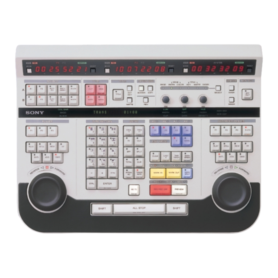
- Page 3 6 Scratchpad Displays data entered from the numeric keypad (see page 1-19). Also displays error messages and setup menu items and settings. 7 TITLE section TITLE 2 EXT KEY button TITLE 1 TITLE (T-TRNS) button T-TRNS 3 MATTE button MATTE Inserts or removes a title key.
-
Page 4: Upper Section
Upper Section 2 EXT KEY (external key) button 3 MATTE button When the TITLE button is lit, press this Press this button, lighting it, to use a color button, lighting it, to use the signal matte signal generated by the built-in color specified in the title key setup menu as the background signal generator as a title key title key source signal. - Page 5 http://getMANUAL.com 4 ENTRY section ENTRY 2 TRIM + 1 (+X) button 1 TRIM – 1 (–X) button TRIM TRIM –1 –X 3 IN button 4 OUT button 5 EFF button 6 SPLIT (T-TIME) button SPLIT T-TIME 7 TOTAL (START) button 8 DUR (SPEED) button TOTAL START...
-
Page 6: Lower Section
Lower Section 1 TRIM – 1 (–X) button 5 EFF (effect) button Trims flashing data in the minus direction. Displays the effect (wipe, dissolve) start TRIM – 1 (trim minus 1): When the point in the R-VTR time counter display displayed data is timecode, subtracts 1 panel. - Page 7 9 PTTRN NO (REEL) button EDIT NO (edit number) (SHIFT + PTTRN NO (wipe pattern number): TRANS TIME): Press this button, Press this button, lighting it, to specify lighting it, to display the 4-digit edit a wipe pattern to use by entering the number of the current edit in the R- pattern number.
- Page 8 Lower Section 5 EDIT MODE section 1 Audio insert buttons 2 A5 to A8 indicators ASMBL EDIT MODE CHG BAS 1ST EDIT 4 ASMBL (1ST EDIT) button 3 V (CHG BAS) button Sets the edit mode. 3 V (CHG BAS) button V (video insert): Press this button, 1 Audio insert buttons lighting it, to conduct video insert...
-
Page 9: System Settings
System Settings Make the following settings on the control panel. MODE buttons • If timecode is already recorded on all the tapes you will be using, press the MODE buttons to light the TC indicators. • If there is no timecode recorded on even one of the tapes, press the MODE buttons to light the CTL indicators. -
Page 10: Status Displays
Status Displays Note Status displays appear only when the video format is 59.94 Hz. When using the optional BKE-701 HD Switcher Board, you can display tape positions and edit data on the main monitor (the video monitor connected to the MONITOR OUT connector of the processor unit). - Page 11 Press the 1ST EDIT (SHIFT + ASSMBL) button. Press the REC/REC OFF button. The ASMBL button starts to flash, and first edit processing is carried out in the following order. 1) A signal generated by the internal background signal generator is recorded for 10 seconds plus the preroll time before the recorder IN point.
-
Page 12: Chapter 4 Editing Operations
Split editing is insert mode editing in which the video and audio IN point are set separately. The BVE-700 allows you to select either the video IN point or the audio IN point as the base point in split editing. However, when you select the video IN point as the base point, separate audio IN points cannot be set on each audio channel. - Page 13 Inserting Titles (Title Key) You can superimpose titles and telop images over the video of your edit. The function that allows you to do this is called title key. Title key source signals and fill signals The signal specified in the title key setup menu is used as the title key source signal.
- Page 14 Inserting Titles (Title Key) Press the TITLE button in the TYPE section, lighting it. The signal input to the TITLE connector of the processor unit is superimposed instantly. The TITLE KEY indicator in the parameter adjustment section lights. If the characters in the title cannot be seen clearly, adjust by rotating knob 1 (CLIP) and knob 2 (GAIN) in the parameter adjustment section.
- Page 15 This interface is enabled when the GPI button on the control panel of the DFS-700/700P is lit. Wipe patterns and transition times set on the control panel of the BVE-700 are set on the DFS-700/700P at the time of recording or preview. 4-59...
- Page 17 Loading Edits From the EDL You can load edits from the EDL into the control panel, modify the edit data, and conduct previews and recording. There are two ways to load edits from the EDL. • Load the edit immediately before or after the current edit. •...
-
Page 18: Chapter 5 Data Management
Edit Data Management To load the edit immediately before or after the current edit Proceed as follows to load the edit immediately before or after the current edit. PLAYER WIPE PATTERN ENTRY RECORDFR/PLAYER EDIT MODE RPLAY RPLY FS (SHIFT + “+”) BS (SHIFT + “–”) To load the previous edit (with an edit number 1 smaller) Press the BS (SHIFT + “–”) button. -
Page 19: System Config
Press the ENTER button. The KEEP ALL EDL message in the scratchpad begins to flash. Press the ALL STOP button. The flashing message in the scratchpad changes to CLR DELETED EDIT. Press the ENTER button. All of the edits that have been targeted for deletion (edits with the letter ‘d’... - Page 20 Edit Data Management Dumping and Loading EDL Data Overview The BVE-700 allows you to dump EDL data to external devices, and to load EDL data from external devices. Dumping EDL data to external devices You can dump EDL data created on the BVE-700 to external devices over the RS-232C interface.
- Page 21 SETUP DATA Menu The SETUP DATA menu is configured as follows. See the pages in parentheses for more information about each item. Level 3 Level 4 Level 2 Level 1 Level 0 (Page 6-10) SETUP DATA SYSTEM CONFIG AUX P3 (Page 6-10) BEEP (Page 6-11)
- Page 22 SETUP DATA Menu (Continued) Level 3 Level 4 Level 2 Level 1 Level 0 SW'ER CONFIG TYPE (Page 6-18) USED BANK (Page 6-21) USED AUX (Page 6-21) (Page 6-21) SRC P1 (Page 6-22) AUDIO MODE MON MODE (Page 6-23) PVW MODE (Page 6-23) CUEUP XPT (Page 6-24)
-
Page 23: Clock Set
(Continued) Level 3 Level 4 Level 2 Level 1 Level 0 PROCESS DELAY P1 IN DELAY (Page 6-34) P2 IN DELAY (Page 6-34) P3 IN DELAY (Page 6-34) (Page 6-34) OUT DELAY (Page 6-35) CLOCK SET DATE YEAR (Page 6-35) MONTH (Page 6-35) DATE... - Page 24 SETUP DATA Menu SETUP DATA Menu Item List This section explains the items in the SETUP DATA menu. SYSTEM CONFIG settings Scratchpad display Status display AUX | P3 = AUX (P3) SETUP DATA When a VTR is connected to the AUX/PLAYER-3 SYSTEM CONFIG.
- Page 25 http://getMANUAL.com SYSTEM CONFIG settings (Continued) Scratchpad display Status display SETUP DATA DMC DIAL = WIDE (NARROW) Specifies the relation between playback speed SYSTEM CONFIG. and angle of rotation when you rotate the search DMC DIAL MODE dial in DMC playback mode. =WIDE (NARROW) WIDE: The angle of rotation needed to vary playback speed from 0% to 100% is about...
- Page 26 SETUP DATA Menu RS-232 PARAMETER settings Scratchpad display Status display SETUP DATA BAUD = 19200 (9600, 38400) RS-232 PARAMETER Sets the communications speed of the RS-232C interface. BAUD RATE 9600: Sets the speed to 9600 bps. =19200 (9600, 38400) 19200: Sets the speed to 19200 bps. 38400: Sets the speed to 38400 bps.
- Page 27 VIDEO MODE settings (Continued) Scratchpad display Status display SETUP DATA PVW MODE = MON (EE, FULL) VIDEO MODE Specifies the operation of the USED BANK and USED AUX BUS during previews, recording, and PREVIEW MODE reviews. = MON (EE, FULL) EE: During previews, transitions between recorder and source video are done by recorder PB/EE control.
- Page 28 SETUP DATA Menu SW’ER CONFIG settings Scratchpad display Status display TYPE = BKE-701 (HDS, DVS, DFS-700) SETUP DATA Selects the type of video switcher. Select the SWITCHER CONFIG switcher in your system. SWITCHER TYPE BKE-701: Specifies control of the BKE-701. =BKE-701 (HDS, DVS, DFS-700) HDS, DVS: Specifies control of the HDS-7000 and compatible.
- Page 29 6-19 Chapter 6 Setup...
- Page 30 6-20 Chapter 6 Setup...
- Page 31 AUDIO MODE settings (Continued) Scratchpad display Status display PVW MODE = MON (EE, FULL) SETUP DATA Specifies the operation of the audio mixer USED AUDIO MODE BANK and USED AUX BUS during previews, PREVIEW MODE recording, and reviews. =MON (EE, FULL) EE: During previews, transitions between recorder and source audio are done by recorder PB/EE control.
- Page 32 SETUP DATA Menu MIXER CONFIG settings Scratchpad display Status display PRTCL = ESAM-II4 (ESAM-II2) SETUP DATA Selects the type of audio mixer. Select the mixer MIXER CONFIGURATION in your system. MIXER TYPE ESAM-II2: Specifies control of the mixer by the =ESAM-II (4CH) (ESAM-II (2CH)) ESAM-II (2CH) protocol.
- Page 33 BKE-701 SETUP Menu The BKE-701 SETUP menu is configured as follows. See the pages in parentheses for more information about each item. Level 0 Level 1 Level 2 BKE-701 SETUP SIGNAL FORMAT FORMAT (Page 6-38) SCREEN (Page 6-38) (Page 6-39) OUTPUT W-CLIP (Page 6-39)
- Page 34 BKE-701 SETUP Menu BKE-701 SETUP Menu Item List This section explains the items in the BKE-701 SETUP menu. SIGNAL FORMAT settings Scratchpad display Status display FORMAT = 1080 (1035) BKE-701 SETUP Specifies the number of effective scanning lines. SIGNAL FORMAT 1080: 1080 effective scanning lines FORMAT 1035: 1035 effective scanning lines...
- Page 35 http://getMANUAL.com MATTE settings Scratchpad display Status display COLOR LIMIT = ON (OFF) BKE-701 SETUP Specifies whether an illegal color limiter is used. MATTE ON: An illegal color limiter is used. COLOR LIMIT OFF: An illegal color limiter is not used. =ON (OFF) Factory default setting: ON LUM MAX = 100 (107)
-
Page 36: Default Setup
BKE-701 SETUP Menu TITLE settings (Continued) Scratchpad display Status display FILL = TITLE (P1, P2, P3/AUX) BKE-701 SETUP Specifies the key fill signal. TITLE P1: Use the signal input to the PLAYER-1 FILL connector as the key fill signal. = TITLE (P1, P2, P3/AUX) P2: Use the signal input to the PLAYER-2 connector as the key fill signal. - Page 38 INIT DATA Menu DUMP/LOAD functions Scratchpad display Status display A BKE-701 SETUP mode message BKE-701 SETUP DUMP: Dumps BKE-701 SETUP menu data from DUMP the backup memory on the CPU board to the external device connected to the EDL connector of the processor unit.
- Page 39 INIT DATA Menu The INIT DATA menu is configured as follows. See the pages in parentheses for more information about each item. Level 0 Level 1 Level 2 Level 3 INIT DATA SHOW START TIME (Page 6-45) 1ST-ED VIDEO SOURCE (Page 6-46) 1ST-ED AUDIO SOURCE (Page 6-46 (2))
- Page 40 INIT DATA Menu (Continued) Level 0 Level 1 Level 2 Level 3 TEST FIRE GPI-1 TEST FIRE (Page 6-51) GPI-2 TEST FIRE (Page 6-51) GPI-3 TEST FIRE (Page 6-51) GPI-4 TEST FIRE (Page 6-51) DEC BASE (Page 6-51) (Page 6-51 (2)) CHANGE BASE MODE OVERFLOW EDIT (Page 6-52)
- Page 41 INIT DATA Menu Item List This section explains the items in the INIT DATA menu. SHOW START TIME setting Scratchpad display Status display STRT = 00 00 00 00 to 23 59 59 29 INIT DATA Sets the default R-VTR IN point value for first SHOW START TIME edits.
- Page 42 INIT DATA Menu 1ST-EDIT VIDEO/SOURCE settings Scratchpad display Status display 1EDVSRC = BLACK (COL BAR, BKGD) INIT DATA Selects the source used in first edits. 1EDVSRC BLACK: When BKE-701 used: Sets the source =BLACK (COL BAR, BKGD VTR, SG) signal to a black signal. When external switcher used: Sets to the cross point set for a black signal.
- Page 43 1ST-ED AUDIO SOURCE settings Scratchpad display Status display 1EDASRC = MUTE (VTR-SG) INIT DATA Specifies the audio signal to use in first edits. 1EDASRC MUTE: Mute. = MUTE (VTR-SG) VTR-SG: Sets the audio signal to a signal generated by the internal signal generator of the VTR.
- Page 45 http://getMANUAL.com PREROLL TIME settings Scratchpad display Status display PRE = ss: ff [absolute value input] INIT DATA ss: ff-ss: ff [relative value input] PREROLL TIME Sets the preroll time, which determines how far =SS: FF VTRs must be rewound past their IN points to achieve synchronization before previews, recording, and so on.
- Page 46 INIT DATA Menu FRAME CONTROL MODE settings Scratchpad display Status display TC MODE = DF (NDF) INIT DATA Specifies whether to process timecode in drop- FRAME CONTROL MODE frame mode or non-drop frame mode. =DF (NDF) If this setting is different for the recorder and players in automatic editing, the recorder’s setting takes priority.
- Page 47 GPI PULSE settings (Continued) Scratchpad display Status display GPI-n TEST FIRE INIT DATA Fires a test GPI pulse from the selected GPI port. GPI PULSE Select a GPI port from among GPI-1 to GPI-4by TEST FIRE pressing the ALL STOP button. >...
- Page 48 INIT DATA Menu CHANGE BASE MODE settings Scratchpad display Status display CHG BASE = CONV (SWAP) INIT DATA Specifies the method used to switch between the CHANGE BASE MODE video or audio signal as the base signal in split editing when the CHG BAS (SHIFT + V) button is = CONV (SWAP) pressed.
- Page 50 INIT DATA Menu SKIP REC settings Scratchpad display Status display SKIP REC = ON (OFF) INIT DATA Specifies whether to use the SKIP REC function. SKIP REC ON: Enable the SKIP REC function. =ON (OFF) OFF: Disable the SKIP REC function. Factory default setting: ON REC MARK settings Scratchpad display...
- Page 51 VTR CONSTANT Menu Item List This section explains the items in the VTR CONSTANT menu. VTR CONSTANT settings Scratchpad display Status display VTR constants are data that define the basic operating conditions of VTRs. Constants for VTRs and other devices likely to be used with this system are stored in system memory as internal data.
- Page 52 VTR CONSTANT Menu To copy VTR constants To copy the VTR constant number for a connected VTR, proceed as follows. Select a user VTR constant number, and press the selection button for the desired VTR. The following message appears in the scratchpad. “COPY XXX CONST.
-
Page 54: Information Menu
INFORMATION Menu The INFORMATION menu displays 7 items of information. The next item appears each time you press the ENTER button or ALL STOP button. Level 0 Level 1 INFORMATION SYSTEM REFERENCE MODE MAIN SOFT VERSION PANEL SOFT VERSION BOOT SOFT VERSION CKG BOARD ID IO BOARD ID MIX BOARD ID... - Page 55 http://getMANUAL.com BOOT SOFT VERSION information Scratchpad display Status display BOOT = xxxxxxxx INFORMATION Displays the version of the boot ROM in the BOOT = xxxxxxxx processor unit. CKG BOARD ID information Scratchpad display Status display CKG BOARD ID = xx INFORMATION Displays the ID of the CKG board.
- Page 56 Storing and Restoring Setup Menus You can store and restore the data of the setup menus listed below, either by storing/ restoring the data for all of the menus at once or by storing/restoring the data for individual menus. SETUP DATA BKE-701 SETUP INIT DATA AUX DATA...
- Page 57 To restore setup menus Proceed as follows. Press the SETUP (SHIFT + DISS) button to put the system into setup mode. To restore an individual menu, navigate to that menu. To restore all of the menus, stay on the current level and proceed to step 3.
- Page 58 Dumping and Loading Setup Menus You can dump setup menu data to the device connected to the EDL (RS-233C) connector, and load the data as required. Data can be dumped and loaded for the following menus. SETUP DATA BKE-701 SETUP INIT DATA AUX DATA To dump setup menus...
- Page 59 Error messages and steps to take (Continued) Error message Description Steps to take R-VTR ERROR (PRE READ) Pre-read editing failed. Check the following. • The recorder is a VTR with a S: CANNOT PRE-READ pre-read function. M: CANNOT PRE-READ • The PRE READ item in the setup menu (INIT DATA) is set to ON.
-
Page 60: Mosaic Effect
Mosaic Effect You can apply a mosaic effect to segments and clips in cut editing. To apply a mosaic effect Proceed as follows. SOURCE TYPE TITLE PATTERN EDGE REMOTE MON OUT COL BAR AUDIO BASE BKGD WIDTH SOFT FADER NEW EDIT BLACK CLIP GAIN... - Page 61 Press the SELECT button or the CTRL + SELECT button so that the indicators for the adjustments you want light or blink. Adjustment Adjustment knobs Button Indicator Cell BKGD blinks 1: Cell aspect ratio CTRL + adjustment SELECT 3: Cell size CTRL + EDGE- 1: Region aspect...
- Page 62 Source Video Adjustment Function (Video Process) You can adjust the luminance and chroma of source video. To apply the video process effect Proceed as follows. SOURCE TYPE TITLE PATTERN EDGE REMOTE MON OUT COL BAR AUDIO BASE BKGD WIDTH SOFT FADER NEW EDIT BLACK...
- Page 63 To turn the video process function on and off, use the A row of the SOURCE section and the EXT KEY button in the TITLE section. Button Function Turns on and off for the signal input to the PLAYER-1 connector Turns on and off for the signal input to the PLAYER-2 connector AUX/P3...
-
Page 64: Wipe Patterns
Wipe Patterns Standard Wipes A-10 Appendix...