
Related Manuals for Sony BKM-17R


Summary of Contents for Sony BKM-17R
- Page 1 4-688-461-11(1) Monitor Control Unit Operating Instructions Before operating the unit, please read this manual thoroughly and retain it for future reference. BKM-17R © 2016 Sony Corporation...
- Page 2 This unit has no power switch. Refer to these numbers whenever you call upon your When installing the unit, incorporate a readily accessible Sony dealer regarding this product. disconnect device in the fixed wiring, or connect the Model No. power plug to an easily accessible socket-outlet near the Serial No.
- Page 3 6. When performing the installation, keep the which case the user will be required to correct the following space away from walls in order to interference at his own expense. obtain proper exhaust and radiation of heat. You are cautioned that any changes or modifications not Lower, Upper: 4.4 cm (1 3/4 inches) or more expressly approved in this manual could void your Right, Left: 1.0 cm (13/32 inches) or more...
- Page 4 H συσκευή δεν πρέπει να εκτίθεται σε σταγόνες ή For the customers in the U.S.A. πιτσιλιές. Αντικείμενα που περιέχουν υγρό, όπως βάζα, SONY LIMITED WARRANTY - Please visit http:// δεν πρέπει να τοποθετούνται επάνω σε αυτήν. www.sony.com/psa/warranty for important information and complete terms and conditions of Türkiye’deki müşteriler için...
-
Page 5: Table Of Contents
Table of Contents Features ............6 Available Monitors and Functions ....7 Location and Function of Parts ..... 9 Front Panel..............9 Rear Panel ............... 12 Handling a USB memory stick ..... 13 Notes on USB memory sticks .......13 Mounting the Unit in a Rack ......14 Connections .......... -
Page 6: Features
Features The BKM-17R is a control unit for the BVM/PVM series business & professional video monitor. Use it to power monitors on and set in sleep mode, perform menu operations, and carry out monitor setup and adjustment. For monitors connectable to this unit and usable functions, see page 7. -
Page 7: Available Monitors And Functions
Available Monitors and Functions For details on how to use each function, refer to the manual of your monitor. Available function Monitor BVM-E251 BVM-X300 PVM-X550 BVM-E series BVM-L series BVM-E171 except PVM-L series BVM-E251/ BVM-E171 BVM-F series ×... - Page 8 Available function Monitor BVM-E251 BVM-X300 PVM-X550 BVM-E series BVM-L series BVM-E171 except PVM-L series BVM-E251/ BVM-E171 BVM-F series × Aspect Blanking-Half × Aspect Blanking-Black × × Side by Side ...
-
Page 9: Location And Function Of Parts
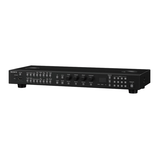
Location and Function of Parts For functions available with your monitor, see page 7. Front Panel OPERATE lamp Factory preset setting The lamp lights when the unit is turned on. BLUE ONLY button CHROMA UP button (USB connector) You can use a USB memory stick (sold separately) to save and load monitor setup and adjustment data. - Page 10 Menu operation buttons The degree of modification is set in the menu of the monitor. MENU button: MONO button: Press to display a monochrome Displays the monitor menu. picture. Press again to clear the menu in the When the button is set to off, the monitor switches main menu.
- Page 11 Monitor selection buttons and lamps PHASE CHROMA BRIGHT CONTRAST When multiple monitors are connected by the network button button button button and connection, one particular monitor, monitor group or all and knob and knob and knob knob monitors are selected by setting the monitor ID number, Group ID number or ALL.
-
Page 12: Rear Panel
Rear Panel DC 12V connector Connect to the DC 12V OUT connector of the monitor by using the supported cables. Supported cables vary depending on the monitor. For BVM-E251/BVM-E171 The output cable of the supplied AC adaptor, SMF- 17R20, or the cable supplied with the controller attachment stand such as BKM-37H For another monitors The output cable of the supplied AC adaptor... -
Page 13: Handling A Usb Memory Stick
– If you eject the USB memory stick, or turn the unit Handling a USB memory off while accessing the data – If you use a USB memory stick near static electricity stick or a magnetic field We recommend backing up important data. ... -
Page 14: Mounting The Unit In A Rack
Attach the rack mount brackets to each side of the prevent cable disconnection. unit with the rack mount bracket attachment screws. BKM-17R (this unit) Rack mount bracket Rack mount bracket attachment screws Screw the rack mount brackets to the rack to mount After connecting the cable to the DC 12V the unit. -
Page 15: Connecting One Monitor
LAN (10/100) DC 12V OUT connector connector SMF-17R20, etc. LAN (10/100) DC 12V connector connector BKM-17R (this unit) NETWORK switch: LAN (10/100) LAN (10/100) Set to PEER TO PEER. connector connector Turn off the power switch of the monitor before connecting the unit. -
Page 16: Specifications
General Connect the output cable on the AC adaptor Power requirements supplied with the unit to the DC 12V connector of BKM-17R the unit. DC IN: 12 V, 0.5 A (supplied with the connected monitor or the connected Note... - Page 17 ANY OTHER MEDIA OR STORAGE SYSTEMS TO RECORD CONTENT OF ANY TYPE. Always verify that the unit is operating properly before use. SONY WILL NOT BE LIABLE FOR DAMAGES OF ANY KIND INCLUDING, BUT NOT LIMITED TO, COMPENSATION OR REIMBURSEMENT ON ACCOUNT OF THE...
-
Page 18: Dimensions
Side Dimensions Unit: mm (inches) Front 1) When using this hole, use a screw which can be inserted into the unit to a depth of 6 to 9 mm ( inches). Dimensions... - Page 19 Sony Corporation...