Table of Contents
Quick Links
Table of Contents

Related Manuals for Sony BVE-700


Summary of Contents for Sony BVE-700
- Page 1 Editing Control Unit BVE-700 Operation Manual 1st Edition (Revised 1) [English]...
- Page 2 This symbol is intended to WARNING alert the user to the presence of important To prevent fire or shock hazard, do not expose the unit to rain or operating and maintenance moisture. (servicing) instructions in the literature accompanying the To avoid electrical shock, do not appliance.
- Page 3 For the customers in Europe AVERTISSEMENT This product with the CE marking complies Afin d’éviter tout risque with both the EMC Directive (89/336/EEC) d’incendie ou d’électrocution, ne and the Low Voltage Directive (73/23/EEC) pas exposer cet appareil à la issued by the Commission of the European pluie ou à...
- Page 4 Für Kunden in Europa Dieses Produkt besitzt die CE- Kennzeichnung und erfüllt sowohl die EMV-Direktive (89/336/EEC) als auch die Direktive Niederspannung (73/23/EEC) der EG-Kommission. Die Erfüllung dieser Direktiven bedeutet Konformität für die folgenden Europäischen Normen: • EN60950: Produktsicherheit • EN55103-1: Elektromagnetische Interferenz (Emission) •...
-
Page 5: Table Of Contents
Table of Contents Overview ..................2 Features of the BVE-700 ............2 Features of the BKE-701 HD Switcher Board (Option) ..3 System Configuration ............. 4 Names and Functions of Parts—Processor Unit ......9 Front Panel ................9 Rear Panel ................10 Connections ................. -
Page 6: Overview
Overview EDL editing The BVE-700 Editing Control Unit is a video editor that enables advanced editing EDLs (Edit Decision Lists) created on this through simple operations. unit can contain up to 100 edits. The unit The BVE-700 is comprised of a control is equipped with an EDL export port, panel and a processor unit. -
Page 7: Features Of The Bke-701 Hd Switcher Board (Option)
Setup menu The title function allows titles and telop The setup menu allows easy configuration images to be superimposed over the video. of the BVE-700 system for your Status displays environment and intended applications. When the 59.94-Hz video format is used,... -
Page 8: System Configuration
Overview System Configuration This section describes the configuration of some editing systems using the BVE-700. Basic system The figure below shows a basic editing system using the BVE-700. This system has one player and one recorder, and allows cut editing in assemble and insert modes. - Page 9 A/B-roll editing systems, one which When the optional BKE-701 HD Switcher uses only HD VTRs, and one which uses Board is installed in the BVE-700 HD VTRs together with a Betacam/ processor unit, HD VTRs can be used to Betacam SP VTR.
- Page 10 Player 2 Audio mixer (HDW-500) HD SDI 4-channel audio Recorder Player 3 (HDW-500) (HDW-500) HD SDI Serial interface (ESAM protocol) HD SDI BVE-700 processor HD SDI unit HD SDI BVE-700 BKE-701 HD control panel Video monitor Switcher Board (main monitor) (option)
- Page 11 Audio mixer (HDW-500) HD SDI Recorder (HDW-500) Player 3 (Betacam/ Betacam SP VTR) Serial interface (ESAM protocol) Up converter HD SDI BVE-700 HD SDI processor HD SDI unit HD SDI BVE-700 BKE-701 control panel Video monitor HD Switcher (main monitor)
- Page 12 Reference sync signal (525 sync) Audio Audio Player Audio mixer Recorder (HDW-500) (HDW-500) Audio Serial interface (ESAM protocol) HD SDI HD SDI (program output) BVE-700 HD SDI processor unit HD SDI BVE-700 control panel BKE-701 Video monitor HD Switcher Board (main monitor) (option)
-
Page 13: Names And Functions Of Parts-Processor Unit
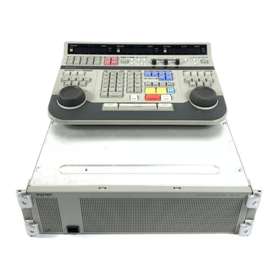
Names and Functions of Parts —Processor Unit This section explains the names and Refer to the User’s Guide for the names functions of the parts of the processor unit. and functions of the parts of the control panel. Front Panel 1 Power indicator 2 Power switch 1 Power indicator... -
Page 14: Rear Panel
Names and Functions of Parts—Processor Unit Rear Panel 1 SDI INPUT section 2 SDI OUTPUT section SDI OUTPUT SDI INPUT MONITOR OUT VIDEO OUT2 VIDEO OUT1 TITLE RECORDER AUX/PLAYER-3 PLAYER-2 PLAYER-1 SWER MIXER RECORDER PLAYER-3 PLAYER-2 PLAYER-1 REF VIDEO IN PANEL AC IN 4 Control connector... - Page 15 The connectors in this section input SDI 4 RECORDER connector (BNC type) (Serial Digital Interface) format signals Connect to the SDI output connector of the from external devices. To use these VTR to be used as the recorder. Signals connectors, the optional BKE-701 HD input to this connector can be output to the Switcher Board must be installed.
- Page 16 1 VIDEO OUT1 (output 1) connector connected to this connector functions as (BNC type) the main monitor. Outputs the video edited on the BVE-700 (program output). Connect to the recorder SDI input connector. 2 VIDEO OUT2 (output 2) connector (BNC type) Outputs the same signals as the VIDEO OUT1 connector.
- Page 17 (D-sub, 9-pin) of the VTR to be used as Connect to the remote control connector Player 1. This enables the BVE-700 to (D-sub, 9-pin) of the VTR to be used as control the VTR remotely. the recorder. This enables the BVE-700 to control the VTR remotely.
- Page 18 BVS This connector is used to transfer EDL cable. data (BVE-9100 format) and BVE-700 setup data between the BVE-700 and 8 GPI (General-Purpose Interface) external devices. connector (D-sub, 15-pin) Connect to the RS-232C connector of the Outputs start pulses for control of telop external device.
-
Page 19: Connections
MIXER RECORDER PLAYER-3 PLAYER-2 PLAYER-1 REF VIDEO IN PANEL AC IN PANEL MIXER REF. VIDEO IN BVE-700 processor unit EDITOR BVE-700 control panel Audio mixer EDITOR Connection cables 75-ohm coaxial cable 9-pin remote control cable BVS cable (supplied) Audio cable... -
Page 20: A/B-Roll Editing System
TITLE RECORDER AUX/PLAYER-3 PLAYER-2 PLAYER-1 SWER MIXER RECORDER PLAYER-3 PLAYER-2 PLAYER-1 REF VIDEO IN PANEL AC IN BVE-700 processor unit MIXER PANEL PLAYER-3 PLAYER-2 REMOTE REF. (9P) VIDEO HD SDI OUT Player 2 Audio mixer REF. VIDEO HD SDI OUT... -
Page 21: Specifications
Specifications Control systems BVE-700 Processor Unit VTR interface and Control Panel 9-pin D-sub connector (× 4), RS-422A Edit functions Controllable VTRs Recorder × 1 Edit modes Insert and assemble editing Player × 3 for video and audio channels Connectable VTR... - Page 22 Specifications General Accessories supplied Power requirements BVS cable (1) 100 to 240 V AC, Operation Manual (1) 50/60 Hz Installation Manual (1) Power consumption User’s Guide (1) Max. 2.5 A Peak inrush current Accessories not supplied (1) Power ON, current probe method: AC power cord 36.0A (240V) For customers in the USA and Canada...
- Page 23 The material contained in this manual consists of information that is the property of Sony Corporation and is intended solely for use by the purchasers of the equipment described in this manual. Sony Corporation expressly prohibits the duplication of any...
- Page 24 Sony Corporation Commnunication System Solutions Network Company Printed in Japan BVE-700 (SY) 2000.07.13 © 2000 3-204-000-02(1)