
Related Manuals for Fujitsu PRIMERGY RX2450 M1


Summary of Contents for Fujitsu PRIMERGY RX2450 M1
- Page 1 Upgrade and Maintenance Manual - English FUJITSU Server PRIMERGY RX2450 M1 Upgrade and Maintenance Manual 09/2021...
-
Page 2: Installing A Gpu Card In Riser Module
All hardware and software names used are trademarks of their respective manufacturers. The contents of this manual may be revised without prior notice. – Fujitsu assumes no liability for damages to third party copyrights or other rights arising from – the use of any information in this manual. - Page 3 Before reading this manual For your safety This manual contains important information for safely and correctly using this product. Carefully read the manual before using this product. Pay particular attention to the accompanying manual "Safety Notes and Regulations" and ensure that these safety notes are understood before using the product.
- Page 4 Please consult the sales staff of Fujitsu if intending to use this product for high safety use. Measures against momentary voltage drop This product may be affected by a momentary voltage drop in the power supply caused by lightning.
- Page 5 HDD, see the following internet address: https://jp.fujitsu.com/platform/server/primergy/harddisk/ Only for Japan: Shielded LAN cables should be used in this product. UK Importer information Fujitsu Services Limited 22 Baker Street, London, W1U 3BW, United Kingdom RX2450 M1 Upgrade and Maintenance Manual...
- Page 6 Version history Issue Issue date Description number V 1.0 03/2021 Initial release V 2.0 09/2021 PDUAL CP100 added Examples for cable routing SATA RAID configurations added Upgrade and Maintenance Manual RX2450 M1...
-
Page 7: Table Of Contents
Content Introduction Concept and target groups of this manual Notational conventions Before you start Basic information 2.1.1 Proceeding 2.1.2 Installing optional components 2.1.3 Replacing a defective component Classification of procedures 2.2.1 Assignment of unit categories 2.2.2 Customer Replaceable Units (CRU) 2.2.3 Upgrade and Repair Units (URU) 2.2.4... - Page 8 Content 3.2.4 Batteries 3.2.5 Modules with Electrostatic-Sensitive Devices (ESD modules) 3.2.6 Transporting the server 3.2.7 Installing the server in the rack 3.2.8 Other important information CE conformity FCC Class A Compliance Statement Environmental protection Basic hardware procedures Using diagnostic information 4.1.1 Locating the defective server 4.1.2...
- Page 9 Content Handling riser modules 4.8.1 Positions of riser modules 4.8.2 Removing a riser module 4.8.3 Installing a riser module Handling the air duct 4.9.1 Positions of riser modules 4.9.2 Removing the air ducts 4.9.3 Installing the air duct Basic software procedures Starting the maintenance task 5.1.1 Backing up the setting information of BIOS or BMC...
- Page 10 Content Hard disk drive (HDD) / solid state disk (SSD) Safety notes Basic information 2.5-inch HDD/SSD configurations 7.3.1 Overview of configurations 7.3.1.1 Configuration with 24 HDD/SSD modules 7.3.2 Installing 2.5-inch HDD/SSD modules 7.3.3 Removing 2.5-inch HDD/SSD modules 7.3.4 Replacing a 2.5-inch HDD/SSD module 7.3.5 Replacing the HDD backplane Fans...
- Page 11 Content GPU cards in riser modules 9.4.1 Installing a GPU card in riser module 1 9.4.2 Removing a GPU card from riser module 1 9.4.3 Replacing a GPU card from riser module 1 9.4.4 Installing a GPU card in riser module 2 9.4.5 Removing a GPU card from riser module 2 9.4.6...
- Page 12 Content Front panel 12.1 Safety notes 12.2 Basic information 12.3 Replacing the front panel System board and components 13.1 Safety notes 13.2 Basic information 13.3 CMOS battery 13.3.1 Replacing the CMOS battery 13.4 System board 13.4.1 Replacing the system board Appendix A 14.1 Mechanical overview...
- Page 13 Content 14.2.4 Acoustic indicators 14.3 Onboard settings 14.4 Minimum startup configuration Appendix B 15.1 Supplied documents RX2450 M1 Upgrade and Maintenance Manual...
- Page 14 Content Upgrade and Maintenance Manual RX2450 M1...
-
Page 15: Introduction
Introduction Concept and target groups of this manual This upgrade and maintenance manual provides instructions for the following procedures: – Upgrading the server configuration by adding optional hardware components. – Upgrading the server configuration by replacing existing hardware components with superior ones. –... - Page 16 Introduction ▶ Describes activities that must be performed in the order shown. [Abc] Indicates keys on the keyboard. Pay particular attention to texts marked with this CAUTION symbol. Failure to observe this warning may endanger your life, destroy the system or lead to the loss of data.
-
Page 17: Before You Start
For Japan: https://www.fujitsu.com/jp/products/computing/servers/primergy/ Please contact your local Fujitsu customer service partner for details on how to order expansion kits or spare parts. RX2450 M1 Upgrade and Maintenance Manual... -
Page 18: Replacing A Defective Component
At the beginning of each procedure, the involved unit category is indicated by one of the symbols introduced in this section. Please ask your local Fujitsu service center for more information. 2.2.2 Customer Replaceable Units (CRU) -
Page 19: Upgrade And Repair Units (Uru)
(Repair Units). For Japan, customer allows only upgrade. For upgrade units as customer replaceable, see: https://www.fujitsu.com/jp/products/computing/servers/primergy/ Server management error messages and diagnostic indicators on the front panel and system board will report defective Upgrade and Repair Units as customer replaceable CSS components. -
Page 20: Field Replaceable Units (Fru)
CAUTION Maintenance procedures involving Field Replaceable Units must be performed exclusively by Fujitsu service personnel or technicians trained by Fujitsu. Please note that unauthorized interference with the system will void the warranty and exempt the manufacturer from all liability. Components that are handled as Field Replaceable Units –... -
Page 21: Average Task Duration
Before you start Please ask your local Fujitsu service center for more information. Average task duration Hardware: 10 minutes The average task duration including preliminary and concluding steps is indicated at the beginning of each procedure next to the procedure class. -
Page 22: Tools You Need At Hand
▶ Ensure to store all printed manuals enclosed with your server in a save place for future reference. ▶ When preparing the maintenance task, ensure that all required manuals are available, see Table 2. If applicable, download the manual from the following address: https://support.ts.fujitsu.com/ For Japan: https://www.fujitsu.com/jp/products/computing/servers/primergy/manual/ Upgrade and Maintenance Manual RX2450 M1... -
Page 23: List Of Documents
Important safety information, available online, Regulations" manual or as a printed copy "安全上のご注意" for Japan "FUJITSU Server Information how to install, set up and operate PRIMERGY RX2450 M1 your server, available online Operating Manual" "FUJITSU Server Instructions for upgrading the server PRIMERGY RX2450 M1... - Page 24 "保証書" for Japan printed copy "Returning used devices" Recycling and contact information, available manual online at https://ts.fujitsu.com/recycling, or as a printed copy "Service Desk" leaflet Not applicable in Japan and other countries that "サポート&サービス" for have different regulations for recycling...
-
Page 25: Important Information
Important information Introduction In this chapter you will find essential information regarding safety when working on your server. Depending on your server or the installed options some information is not valid for your server. CAUTION ▶ Before installing and starting up a server, please observe the safety instructions listed in the following section. -
Page 26: Before Starting Up
Important information ▶ Only valid for non hot-plug components Before installing/removing internal components to/from the server, turn off the server, all peripheral devices, and any other connected devices. Also unplug all power cords from the power outlet. Failure to do so can cause electric shock or damage. - Page 27 Important information ▶ If a DC power cord is used, the server must be connected to a proper DC source and earth ground stud/end. ▶ Ensure that the server is connected to a properly grounded power outlet close to the server. ▶...
- Page 28 Important information ▶ Proper operation of the server (in accordance with IEC 60950-1/62368-1 resp. EN 60950-1/62368-1) is only ensured if the server is completely assembled and the rear covers for the installation slots have been fitted (electric shock, cooling, fire protection, interference suppression). ▶...
-
Page 29: Batteries
Important information ▶ Install the screw removed during installation/detaching internal options in former position. To use a screw of the different kind can cause a breakdown of equipment. ▶ The procedure of installation on this notes might change depending on a configuration of option. - Page 30 Important information Figure 1: ESD label The ESD label can be different. When you handle ESD modules, you must always observe the following points: ▶ Switch off the server and remove the power plugs from the power outlets before installing or removing ESD modules. ▶...
-
Page 31: Transporting The Server
Important information 3.2.6 Transporting the server CAUTION ▶ Only transport the server in its original packaging or in packaging that protects it from impacts and jolts. In Japan and APAC, transporting the server in its original packaging does not apply. ▶... -
Page 32: Installing The Server In The Rack
Important information 3.2.7 Installing the server in the rack CAUTION ▶ For safety reasons, at least 2 people are required to install the server in the rack because of its weight and size. (For Japan, see "安全上のご注意".) ▶ Never lift the server into the rack using the handles on the front panel. -
Page 33: Ce Conformity
▶ Select the subclass, e.g. "Rack server". ▶ Select your server, e.g. "PRIMERGY RX2450 M1". ▶ Select the document, e.g. "CE Cert PRIMERGY RX2450 M1". FCC Class A Compliance Statement If there is an FCC statement on the device, it applies to the products covered in this manual, unless otherwise specified herein. -
Page 34: Environmental Protection
▶ Consult the dealer or an experienced radio/TV technician for help. Fujitsu is not responsible for any radio or television interference caused by unauthorized modifications of this equipment or the substitution or attachment of connecting cables and equipment other than those specified by Fujitsu. The correction of interferences caused by such unauthorized modification, substitution or attachment will be the responsibility of the user. - Page 35 Important information Packaging information This packaging information does not apply in Japan and APAC. Do not throw away the packaging. You may need it later for transporting the server. If possible, the equipment should only be transported in its original packaging. Information on handling consumables Please dispose of printer consumables and batteries in accordance with the applicable national regulations.
- Page 36 More information can be found at: https://ts.fujitsu.com/recycling Details regarding the return and recycling of devices and consumables within Europe can also be found in the "Returning used devices" manual, via your local Fujitsu branch, or at: https://ts.fujitsu.com/recycling Upgrade and Maintenance Manual RX2450 M1...
-
Page 37: Basic Hardware Procedures
Basic hardware procedures Using diagnostic information 4.1.1 Locating the defective server Use the ID indicators for easy identification of the server, especially when working in a datacenter environment or a server room: ▶ Press the ID button on the I/O panel or use the IPMI to switch on the ID identicators. -
Page 38: Disconnecting The Power Cord
Basic hardware procedures ▶ Inform the system administrator that the server will be shut down and put offline. ▶ Terminate all applications. ▶ Perform the required procedures described in the preliminary steps of each upgrade or maintenance task. ▶ Shut down the server. If the system is running an ACPI-compliant operating system (OS), pressing the On/Off button will perform a graceful shutdown. -
Page 39: Getting Access To The Component
Basic hardware procedures Figure 3: Disconnecting the power cord ▶ Disconnect the power cord from the PSU. Getting access to the component 4.4.1 Safety notes CAUTION ▶ Only for non-hot plug components: ● Before removing or attaching covers, turn off the server, all peripheral devices, and any other connected devices. -
Page 40: Extending The Server Out Of The Rack
Basic hardware procedures 4.4.2 Extending the server out of the rack CAUTION ▶ Use the anti-tilt plate to prevent the rack from tipping when installing the rack. Pulling the server out of the rack without having installed the anti-tilt plate may cause the rack to tip over. ▶... -
Page 41: Removing The Server From The Rack
Basic hardware procedures ▶ Pull the server out of the rack until it locks in place (1). CAUTION ▶ Do not use the extended server as a surface on which to put things or as a work surface, and strictly avoid leaning on or against it. - Page 42 Basic hardware procedures For configurations above 55 kg: At least four people are needed to lift the server out of the rack cabinet. Additionally, a lifter is required in the following cases: – The server weighs more than 50 kg. –...
-
Page 43: Removing The Top Cover
Basic hardware procedures 4.4.4 Removing the top cover Tools: Phillips PH2 / (+) No. 2 screw driver Removing the top cover Figure 6: Removing the top cover ▶ Remove one screw on each side (1). ▶ Press the two buttons inward to release the locking mechanism (2). ▶... -
Page 44: Reassembling
Basic hardware procedures Reassembling 4.5.1 Safety notes CAUTION ▶ Before attaching the covers, make sure no unnecessary parts or tools are left inside the server. ▶ The top cover must be replaced as soon as possible for purposes of cooling, to comply with EMC regulations (regulations regarding electromagnetic compatibility) and to prevent fires. -
Page 45: Installing The Server In The Rack
Basic hardware procedures ▶ Place the cover onto the chassis (1). ▶ Push the cover to the front side (2). ▶ Fasten the cover with one screw on each side (3). 4.5.3 Installing the server in the rack CAUTION At least two people are needed to position the server on the rack rails. (For Japan, see "安全上のご注意".) For configurations below 32 kg: At least two people are needed to lift the server into the... - Page 46 Basic hardware procedures Additionally, a lifter is required in the following cases: – The server weighs more than 50 kg. – The server weighs more than 21 kg and is to be installed above the height of 25 U. When using a lifter, this installation procedure needs to be carried out by maintenance personnel.
-
Page 47: Sliding The Server Into The Rack
Basic hardware procedures ▶ Push both extended rack rails to the chassis with a thumb (1). ▶ Set the back-end of both inner rails into the extended rack rails (2). ▶ Push evenly on both sides of the front until the rack rails click into the fully extended position (3). -
Page 48: Connecting The Power Cord
Basic hardware procedures ▶ Fasten the server to the rack cabinet with the knurled screws (see circles). ▶ Connect all cables except the power cord to the server rear. Connecting the power cord 4.6.1 Connecting the power cord CAUTION The AC PSU adjusts automatically to any mains voltage in the range from 100 V - 127 V or 200 V - 240 V. -
Page 49: Switching On The Server
Basic hardware procedures Figure 12: Fixing the power cord and the PSU by cable tie ▶ Loop the cable tie around the power connector and the handle of the PSU (1). ▶ Pull tight the cable tie (2) to secure the power connector. ▶... -
Page 50: Handling Riser Modules
Basic hardware procedures Handling riser modules 4.8.1 Positions of riser modules Figure 13: Positions of riser modules Riser module 1, offers slot 3 and 4 Riser module 2, offers slot 1, 2 and 6 4.8.2 Removing a riser module Figure 14: Position of the locks Upgrade and Maintenance Manual RX2450 M1... - Page 51 Basic hardware procedures Figure 15: Opening the locks ▶ Open the locks (1). ▶ Pull-out the locks (2). Removing the riser module 1 Figure 16: Removing the screw ▶ Remove the screw (see circle). RX2450 M1 Upgrade and Maintenance Manual...
- Page 52 Basic hardware procedures Figure 17: Removing the riser module 1 ▶ Pull out the riser module using the blue touch areas. Avoid to hit the riser card to surroundings while pulling it out. It may cause malfunction. Removing the riser module 2 Figure 18: Removing the screws ▶...
- Page 53 Basic hardware procedures Figure 19: Removing the riser module 2 ▶ Pull out the riser module using the blue touch areas. Avoid to hit the riser card to surroundings while pulling it out. It may cause malfunction. RX2450 M1 Upgrade and Maintenance Manual...
-
Page 54: Installing A Riser Module
Basic hardware procedures 4.8.3 Installing a riser module Installing the riser module 1 Figure 20: Connecting the GPU power cable ▶ If GPU is installed: Connect the power cable of the GPU to the system board connector "GPU PWR3". Upgrade and Maintenance Manual RX2450 M1... - Page 55 Basic hardware procedures Figure 21: Routing the GPU power cable ▶ Route the GPU power cable as shown. CAUTION ▶ Ensure that the GPU is fixed well without any tilting issue. Figure 22: Inserting the riser module 1 ▶ Insert the riser module 1. CAUTION ▶...
- Page 56 Basic hardware procedures Figure 23: Position of the lock (see circle) Figure 24: Locking the lock of riser module 1 ▶ Push in the lock in direction of the arrow (1). ▶ Close the lock (2). ▶ Ensure that the lock is fixed well (3). Figure 25: Fastening the screw ▶...
- Page 57 Basic hardware procedures Installing the riser module 2 Figure 26: Connecting the GPU power cable ▶ If GPU is installed: Connect the power cables of the GPUs to the system board connectors "GPU PWR1" and "GPU PWR2". Figure 27: Routing the GPU power cable ▶...
- Page 58 Basic hardware procedures CAUTION ▶ Ensure that all GPUs are fixed well without any tilting issue. Figure 28: Inserting the riser module 2 ▶ Insert the riser module 2. CAUTION ▶ Ensure that the riser card is securely plugged in the PCIe slot on the system board, and there should not be any significant tilting and gap in the area.
- Page 59 Basic hardware procedures Figure 29: Bracket guide pins ▶ Ensure that the two bracket guide pins match the CSE slot. Figure 30: AOC golden finger and system board guide pin ▶ Ensure that the AOC golden finger matches the system board slot (1). ▶...
- Page 60 Basic hardware procedures Figure 32: Locking the lock of riser module 2 ▶ Push in the lock in direction of the arrow (1). ▶ Close the lock (2). ▶ Ensure that the lock is fixed well (3). Figure 33: Fastening the screw ▶...
-
Page 61: Handling The Air Duct
Basic hardware procedures Handling the air duct 4.9.1 Positions of riser modules Figure 34: Overview: air ducts Air duct 1 (CPU1) Air duct 2 (CPU2) RX2450 M1 Upgrade and Maintenance Manual... -
Page 62: Removing The Air Ducts
Basic hardware procedures 4.9.2 Removing the air ducts Removing the air ducts Figure 35: Removing the air ducts ▶ Remove the two CPU air ducts upward. Upgrade and Maintenance Manual RX2450 M1... -
Page 63: Installing The Air Duct
Basic hardware procedures 4.9.3 Installing the air duct Installing CPU air ducts Figure 36: Preparing air duct ▶ Place the air duct on CPU 1 between P1-DIMM A1 and heat sink, P1- DIMM E1 and heat sink. ▶ Place the air duct on CPU 2 between P2-DIMM A1 and heat sink, P2- DIMM E1 and heat sink. - Page 64 Basic hardware procedures Installing GPU air ducts Only valid for configurations with GPU A100. Figure 38: Placing GPU air duct ▶ Place the air duct on CPU 1 between P1-DIMM C2 and heat sink, P1- DIMM H2 and heat sink. Upgrade and Maintenance Manual RX2450 M1...
- Page 65 Basic hardware procedures Figure 39: Preparing GPU air duct ▶ Remove the marked part of the air duct for CPU 2. RX2450 M1 Upgrade and Maintenance Manual...
- Page 66 Basic hardware procedures Figure 40: Installing GPU air duct ▶ Place the air duct on CPU 2 between P2-DIMM D1 and heat sink, P2- DIMM E2 and heat sink. Upgrade and Maintenance Manual RX2450 M1...
-
Page 67: Basic Software Procedures
For more information on suitable backup software solutions and related documentation, see the Fujitsu web pages. 5.1.3 Switching on the ID indicators For easy identification of the server, switch on the ID indicators, especially when working in a datacenter environment or a server room. -
Page 68: Completing The Maintenance Task
For Japan: https://www.fujitsu.com/jp/products/computing/servers/primergy/downloads/ Fujitsu does not assume responsibility for any damage done to the server or for the loss of any data resulting from BIOS updates. BIOS flash procedure ▶ Perform the BIOS flash procedure as described in the "BIOS Setup Utility"... -
Page 69: Enabling Option Rom Scan
Basic software procedures BMC recovery procedure ▶ Perform the BMC recovery procedure as described in the "BMC User Guide" of your server. 5.2.2 Enabling Option ROM scan In order to configure an expansion card that has been installed or replaced, the Option ROM of the card has to be enabled in the BIOS. -
Page 70: Verifying The System Time Settings
Basic software procedures 5.2.3 Verifying the system time settings This task only applies to Linux environments. After the system board has been replaced, the system time is set automatically. By default, the RTC (Real Time Clock) time standard is set as the local time. If a Linux OS is used and the hardware clock has been configured as UTC (Universal Time, Coordinated) in the OS, the BMC local time may not be mapped correctly. -
Page 71: Updating The Nic Configuration File In A Linux Environment
Basic software procedures You can clear the System Event Log (SEL) using the BMC web interface. Viewing the SEL using the BMC web interface ▶ Log in to the BMC web interface. ▶ Open the Logs & Reports menu. ▶ Click IPMI Event Log to open the System Event Log page. ▶... -
Page 72: Performing A Raid Array Rebuild
Basic software procedures interface card in the related NIC configuration file of the Linux OS. When replacing a network controller or the system board with onboard LAN controllers in a server running Linux OS, the MAC address will change but not automatically be updated in the definition file. -
Page 73: Looking For The Mac Address Of A Lan Controller
Basic software procedures Figure 41: Progress bar (RAID array rebuild) CAUTION The system is now operational, however, data redundancy will not be available until the RAID array rebuild is complete. Depending on the HDD capacity the overall process can take up to several hours, in some cases even days. -
Page 74: Switching Off The Id Identicators
Basic software procedures Using the BIOS ▶ Enter the BIOS. ▶ Select the Configuration menu. The addresses are displayed at the one or more of the following (it depends on the behavior of the UEFI driver included in each controller). 1. -
Page 75: Power Supply Unit (Psu)
Power supply unit (PSU) Safety notes CAUTION ▶ Do not disassemble the PSU. Doing so may cause electric shock. ▶ Areas around the PSU may remain extremely hot after shutdown. After shutting down the server, wait for hot components to cool down before removing the PSU. -
Page 76: Redundant Power Supply
Power supply unit (PSU) PSU configurations PSU 1 PSU 2 Figure 42: PSU bays AC PSU Input Output 100 V - 127 V 1000 W 80 PLUS Platinum 200 V - 240 V 1600 W Assembly rules – Always install a dummy cover into an unused PSU bay to comply with applicable EMC regulations and satisfy cooling requirements. - Page 77 Power supply unit (PSU) A second PSU of the same type as the already existing PSU can be installed while the system is in operation. Preliminary steps No steps needed. Removing the dummy cover Figure 43: Removing the dummy cover ▶...
- Page 78 Power supply unit (PSU) Installing a hot-plug PSU Figure 44: Installing the PSU ▶ Push the handle of the PSU halfway upward in the direction of the arrow (1). ▶ Push the PSU into its bay as far as it will go until the release latch snaps in place (2).
-
Page 79: Removing A Hot-Plug Psu
Power supply unit (PSU) Concluding steps ▶ "Connecting the power cord" on page 6.3.2 Removing a hot-plug PSU Customer Replaceable Hardware: 5 minutes Unit (CRU) Tools: tool-less Preliminary steps ▶ Only when replacing a PSU in a non-redundant configuration: "Shutting down the server"... -
Page 80: Replacing A Hot-Plug Psu
Power supply unit (PSU) CAUTION Excessive temperatures could damage system components. ▶ Never leave the bay for the hot-plug PSU empty for more than two minutes during operation. Installing the dummy cover Figure 47: Installing the dummy cover ▶ Insert the dummy cover into the empty bay with the impressed arrow symbol facing to the left (see circle). - Page 81 Power supply unit (PSU) Tools: tool-less CAUTION ▶ When replacing a PSU in a non-redundant PSU configuration, the server must be switched off first. ▶ Replace the PSU after specifying the one that breaks down at work by revitalization. Preliminary steps ▶...
- Page 82 Power supply unit (PSU) Upgrade and Maintenance Manual RX2450 M1...
-
Page 83: Hard Disk Drive (Hdd) / Solid State Disk (Ssd)
Hard disk drive (HDD) / solid state disk (SSD) Safety notes CAUTION ▶ Before removing several HDD/SSD modules, make sure that all HDD/SSD modules can be reinstalled into their original bay. Otherwise, data may be lost. ▶ Do not touch the circuitry on boards or soldered parts. Hold circuit boards by their metallic areas or edges. -
Page 84: Basic Information
Hard disk drive (HDD) / solid state disk (SSD) Basic information The HDD or SSD and the installation frame together make up the HDD module or SSD module. The server is shipped with one of the following HDD or SSD subsystem: –... -
Page 85: Installing 2.5-Inch Hdd/Ssd Modules
Hard disk drive (HDD) / solid state disk (SSD) Position Component HDD5 HDD6 HDD7 HDD8 HDD9 HDD10 HDD11 HDD12 HDD13 HDD14 HDD15 HDD16 HDD17 HDD18 HDD19 HDD20 HDD21 HDD22 HDD23 7.3.2 Installing 2.5-inch HDD/SSD modules Customer Replaceable Hardware: 5 minutes Unit (CRU) Tools: Phillips PH1 / (+) No. - Page 86 Hard disk drive (HDD) / solid state disk (SSD) Preliminary steps ▶ Locate the correct drive bay, see "Overview of configurations" on page Removing a 2.5-inch HDD/SSD dummy module The dummy module is installed in the installation frame of the HDD/SSD module.
- Page 87 Hard disk drive (HDD) / solid state disk (SSD) Figure 50: Removing a 2.5-inch HDD/SSD module ▶ Pull the HDD/SSD module out of its bay. Figure 51: Removing a 2.5-inch HDD/SSD dummy module (A) ▶ Remove the four screws. These screws are not used to mount the actual HDD/SSD. RX2450 M1 Upgrade and Maintenance Manual...
- Page 88 Hard disk drive (HDD) / solid state disk (SSD) Figure 52: Removing a 2.5-inch HDD/SSD dummy module (B) ▶ Turn around the installation frame. ▶ Remove the 2.5-inch HDD/SSD dummy module upward. CAUTION ▶ Keep the dummy module for future use. ▶...
- Page 89 Hard disk drive (HDD) / solid state disk (SSD) Installing a 2.5-inch HDD/SSD module Figure 53: Installing a 2.5-inch HDD/SSD (A) ▶ Insert the HDD/SSD in the installation frame with the connector end toward the rear of the installation frame. Figure 54: Installing a 2.5-inch HDD/SSD (B) ▶...
- Page 90 Hard disk drive (HDD) / solid state disk (SSD) Figure 55: Installing the 2.5-inch HDD/SSD module ▶ Insert the HDD/SSD module into a drive bay and carefully push back as far as it will go. Figure 56: Closing the locking lever ▶...
-
Page 91: Removing 2.5-Inch Hdd/Ssd Modules
Hard disk drive (HDD) / solid state disk (SSD) Concluding steps No steps needed. 7.3.3 Removing 2.5-inch HDD/SSD modules Customer Replaceable Hardware: 5 minutes Unit (CRU) Tools: tool-less Preliminary steps ▶ If the HDD/SSD module to be removed is combined into a RAID array, please proceed as follows: RAID level Procedure... - Page 92 Hard disk drive (HDD) / solid state disk (SSD) CAUTION All data on all HDDs/SSDs in the array will be lost when deleting the RAID array! ▶ Be sure to back up your data before deleting a RAID array. ▶ For more information, see the "ServerView Suite RAID Management"...
-
Page 93: Replacing A 2.5-Inch Hdd/Ssd Module
Hard disk drive (HDD) / solid state disk (SSD) Figure 57: Installing the 2.5-inch dummy module ▶ Push the dummy module into the empty bay until it engages. Concluding steps No steps needed. 7.3.4 Replacing a 2.5-inch HDD/SSD module Customer Replaceable Hardware: 5 minutes Unit (CRU) Tools:... - Page 94 Hard disk drive (HDD) / solid state disk (SSD) CAUTION ▶ Only remove an HDD/SSD module during operation if the drive is not currently being accessed. Observe the indicators on the corresponding HDD/SSD module, see "Indicators on hot-plug HDD / SSD / PCIe SSD modules" on page 208.
-
Page 95: Replacing The Hdd Backplane
Hard disk drive (HDD) / solid state disk (SSD) Installing the new 2.5-inch HDD module ▶ Install the HDD/SSD module, see "Installing 2.5-inch HDD/SSD modules" on page Concluding steps ▶ If the HDD/SSD is configured using a RAID controller with a RAID level higher than "0", the rebuild will start automatically, see "Performing a RAID array rebuild"... - Page 96 Hard disk drive (HDD) / solid state disk (SSD) Removing the defective HDD backplane Figure 58: Disconnecting all cables ▶ Disconnect all cables from the HDD backplane as shown. ▶ Pull out assembled HDD modules. Figure 59: Removing the HDD backplane ▶...
- Page 97 Hard disk drive (HDD) / solid state disk (SSD) ▶ Remove the HDD backplane. Installing the new HDD backplane Figure 60: Installing the HDD backplane ▶ Place the HDD backplane on the gap on the chassis. ▶ Fasten the upper four screws (see blue circles). ▶...
- Page 98 Hard disk drive (HDD) / solid state disk (SSD) ▶ Connect all cables to the HDD backplane. For the cable plan, see "Appendix B" on page 219. Concluding steps ▶ Insert all HDD/SSD modules, see "Installing 2.5-inch HDD/SSD modules" on page Make sure that you reinstall the HDD/SSD module in the bay it was located before the HDD backplane replacement.
-
Page 99: Fans
Fans Safety notes CAUTION ▶ Do not damage or modify internal cables or devices. Doing so may cause a device failure, fire, or electric shock. ▶ Devices and components inside the server remain hot after shutdown. After shutting down the server, wait for hot components to cool down before installing or removing internal options. -
Page 100: Replacing A Fan Module
Fans Numbering of the fan modules Figure 62: Numbering of the fan modules Fan 1 Fan 3 Fan 2 Fan 4 Replacing a fan module Customer Replaceable Hardware: 10 minutes Unit (CRU) Tools: tool-less Preliminary steps ▶ "Locating the defective server" on page ▶... - Page 101 Fans ▶ "Removing the top cover" on page Removing the defective fan module Figure 63: Removing the fan module ▶ Disconnect the corresponding fan cable from the system board (1). ▶ Lift the system fan out of the chassis (2). RX2450 M1 Upgrade and Maintenance Manual...
- Page 102 Fans Installing the new fan module Figure 64: Installing the fan module ▶ Insert the fan module into the chassis (1). ▶ Connect the corresponding fan cable to the system board (2). Concluding steps ▶ "Installing the top cover" on page ▶...
-
Page 103: Expansion Cards And Riser Cards
Expansion cards and riser cards Safety notes CAUTION ▶ Do not damage or modify internal cables or devices. Doing so may cause a device failure, fire, or electric shock. ▶ Devices and components inside the server remain hot after shutdown. After shutting down the server, wait for hot components to cool down before installing or removing internal options. - Page 104 Expansion cards and riser cards Figure 65: Overview PCIe slots for riser cards PCIe slot for ultra riser card (riser PCIe slot for riser card left (riser module 2) module 1) PCIe slot for riser card right (used for AOC card) Upgrade and Maintenance Manual RX2450 M1...
-
Page 105: Expansion Cards In Riser Modules
Figure 66: Positions of riser modules and AOC card Riser module 2 Riser module 1 AOC card For the latest information on hardware options, see the hardware configurator of your server, available online at the following address: https://www.fujitsu.com/fts/products/computing/servers/primergy/ index.html For Japan: https://www.fujitsu.com/jp/products/computing/servers/primergy/ Expansion cards in riser modules 9.3.1... - Page 106 Expansion cards and riser cards Preliminary steps ▶ "Shutting down the server" on page ▶ "Disconnecting the power cord (AC PSU)" on page ▶ "Getting access to the component" on page ▶ Remove the riser module 1, see "Removing the riser module 1" on page Installing the RAID controller in riser module 1 Figure 67: Removing the slot cover ▶...
-
Page 107: Removing A Raid Controller From Riser Module 1
Expansion cards and riser cards Figure 68: Installing the RAID controller ▶ Carefully insert the RAID controller into the PCIe slot and press down firmly until it is fully seated in the slot. ▶ Fasten the slot bracket with the screw. ▶... - Page 108 Expansion cards and riser cards Preliminary steps ▶ "Shutting down the server" on page ▶ "Disconnecting the power cord" on page ▶ "Getting access to the component" on page ▶ Remove the riser module 1, see "Removing the riser module 1" on page Removing the RAID controller from riser module 1 ▶...
-
Page 109: Replacing A Raid Controller From Riser Module 1
Expansion cards and riser cards ▶ Install the slot cover to slot 4 and fasten the screw (see circle). Concluding steps ▶ Install the riser module 1, see "Installing the riser module 1" on page ▶ "Reassembling" on page ▶ "Connecting the power cord"... -
Page 110: Installing An Expansion Card In Riser Module 2
Expansion cards and riser cards Concluding steps ▶ Install the riser module 1, see "Installing the riser module 1" on page ▶ "Reassembling" on page ▶ If applicable, connect external cables to the expansion card. ▶ "Connecting the power cord" on page ▶... - Page 111 Expansion cards and riser cards Figure 72: Removing the slot cover - example slot 2 ▶ Remove the screw of the slot cover for the desired slot (see circle). ▶ Remove the slot cover. CAUTION ▶ Keep the slot cover for future use. ▶...
- Page 112 Expansion cards and riser cards Example PDUAL CP100 in slot 6 Figure 73: PDUAL CP100 PDUAL CP100 Screws Figure 74: Removing the slot bracket ▶ Remove the two screws (see circles). ▶ Remove the slot bracket. Upgrade and Maintenance Manual RX2450 M1...
- Page 113 Expansion cards and riser cards Figure 75: Installing M.2 SSDs (A) ▶ If applicable, insert the two M.2 SDDs in a slight angle. Figure 76: Installing M.2 SSDs (B) ▶ Fasten each SSD with one screw (see circles). RX2450 M1 Upgrade and Maintenance Manual...
- Page 114 Expansion cards and riser cards Figure 77: Installing the PDUAL CP100 in the riser module 2 ▶ Install the PDUAL CP100 in slot 6. ▶ Fasten the PDUAL CP100 with one screw (see circle). One screw is left over and can be discarded. Concluding steps ▶...
-
Page 115: Removing An Expansion Card From Riser Module 2
Expansion cards and riser cards 9.3.5 Removing an expansion card from riser module 2 Upgrade and Repair Unit Hardware: 10 minutes (URU) Tools: Phillips PH2 / (+) No. 2 screw driver Preliminary steps ▶ "Shutting down the server" on page ▶... -
Page 116: Replacing An Expansion Card From Riser Module 2
Expansion cards and riser cards Figure 79: Installing the slot cover - example slot 2 ▶ Install the slot cover. ▶ Fasten the screw (see circle). Concluding steps ▶ Install the riser module 2, see "Installing the riser module 2" on page ▶... - Page 117 Expansion cards and riser cards ▶ "Disconnecting the power cord" on page ▶ "Getting access to the component" on page ▶ "Locating the defective component" on page ▶ Remove the riser module 2, see "Removing the riser module 2" on page Removing the defective expansion card ▶...
-
Page 118: Examples For Cable Routing
Expansion cards and riser cards 9.3.7 Examples for cable routing 9.3.7.1 SATA RAID configurations of 16 HDDs/SSDs Preparation Figure 80: Preparation for the cable routing (A) Figure 81: Preparation for the cable routing (B) Upgrade and Maintenance Manual RX2450 M1... - Page 119 Expansion cards and riser cards ▶ Remove the cable CBL-SAST-1295-100. ▶ Cut and remove three cable ties (see blue circles). ▶ Disconnect the cable from the HDD backplane and the system board (see orange circles). ▶ Thread the cable through the fan bracket and remove it front ward. Please press latch of cable plug to avoid interference between the cable plug and the fan bracket.
- Page 120 Expansion cards and riser cards Configuration with one RAID controller SAS#2 SAS#3 SAS#4 SAS#5 Figure 84: Routing cables 4x CBL-SAST-0531 (A) Figure 85: Routing cables 4x CBL-SAST-0531 (B) ▶ Connect the four cables to the connectors "SAS#2", "SAS#3", "SAS#4" and "SAS#5"...
- Page 121 Expansion cards and riser cards Configuration with two RAID controllers SAS#2 SAS#3 SAS#4 SAS#5 Figure 86: Routing cables 4x CBL-SAST-0531 (A) Figure 87: Routing cables 4x CBL-SAST-0531 (B) ▶ Connect two cables to the connectors "SAS#2" and "SAS#3" on the HDD backplane and to the connectors "C0"...
-
Page 122: Sata Raid Configurations Of 20 Hdds/Ssds
Expansion cards and riser cards ▶ Fasten the cables with three cable ties (see blue circles). ▶ Fasten the cables with the cable holder (see orange circle). 9.3.7.2 SATA RAID configurations of 20 HDDs/SSDs Preparation Figure 88: Preparation for the cable routing (A) Upgrade and Maintenance Manual RX2450 M1... - Page 123 Expansion cards and riser cards Figure 89: Preparation for the cable routing (B) ▶ Remove the cables CBL-SAST-1295-100 and cable CBL-SAST-1257-100. ▶ Cut and remove four cable ties (see blue circles). ▶ Disconnect the cables from the HDD backplane and the system board (see orange circles).
- Page 124 Expansion cards and riser cards Configuration with two RAID controllers SAS#1 SAS#2 SAS#3 SAS#4 SAS#5 Figure 91: Routing cables 5x CBL-SAST-0531 (A) Figure 92: Routing cables 5x CBL-SAST-0531 (B) Upgrade and Maintenance Manual RX2450 M1...
-
Page 125: Gpu Cards In Riser Modules
Expansion cards and riser cards ▶ Connect four cables to the connectors "SAS#1", "SAS#2", "SAS#3" and "SAS#4" on the HDD backplane and to the connectors "C0", "C1", "C2" and "C3" on the first RAID controller. ▶ Connect one cable to the connectors "SAS#5" on the HDD backplane and to the connector "C0"... - Page 126 Expansion cards and riser cards Figure 93: Removing the slot covers ▶ Remove the screws (see circles) and remove the slot covers. CAUTION ▶ Keep the slot cover for future use. ▶ If the expansion card is removed and not replaced with a new one, the slot cover must be reinstalled due to cooling, to comply with applicable EMC regulations and to protect against fire.
- Page 127 Expansion cards and riser cards Figure 95: Installing the GPU card ▶ Carefully insert the GPU card into the PCIe slot and press down firmly until it is fully seated in the slot (1). ▶ Fasten the slot bracket with two screws (2). Figure 96: Fastening the back side of the GPU ▶...
- Page 128 Expansion cards and riser cards Figure 97: Fastening the top side of the GPU ▶ Fasten the GPU on the top side with two screws (see circles). ▶ Connect the power cable to the GPU. ▶ Connect the power cable to connector "GPU PWR3" on the system board. ▶...
-
Page 129: Removing A Gpu Card From Riser Module 1
Expansion cards and riser cards Concluding steps ▶ "Reassembling" on page ▶ "Connecting the power cord" on page ▶ "Switching on the server" on page 9.4.2 Removing a GPU card from riser module 1 Upgrade and Repair Unit Hardware: 10 minutes (URU) Tools: –... - Page 130 Expansion cards and riser cards Figure 99: Loosening the screws on the back side of the GPU ▶ Loosen the two screws on the back side of the riser module 1 (see circles). Figure 100: Removing the GPU card ▶ Remove the two screws from the top side of the riser module 1 (1). ▶...
- Page 131 Expansion cards and riser cards Figure 101: Fastening the two screws to the riser module 1 ▶ Fasten the two screws on the top side of the riser module 1 (see circles). Figure 102: Installing the slot covers ▶ Install the slot covers and fasten the screws (see circles). Concluding steps ▶...
-
Page 132: Replacing A Gpu Card From Riser Module 1
Expansion cards and riser cards 9.4.3 Replacing a GPU card from riser module 1 Upgrade and Repair Unit Hardware: 15 minutes (URU) Tools: – Phillips PH1 / (+) No. 1 screw driver – Phillips PH2 / (+) No. 2 screw driver Preliminary steps ▶... - Page 133 Expansion cards and riser cards ▶ "Switching on the server" on page 9.4.4 Installing a GPU card in riser module 2 Upgrade and Repair Unit Hardware: 10 minutes (URU) Tools: – Phillips PH1 / (+) No. 1 screw driver – Phillips PH2 / (+) No. 2 screw driver The GPU card can only be installed in slot 1 for riser module 2.
- Page 134 Expansion cards and riser cards ▶ Remove the screws (see circles) and remove the slot covers. CAUTION ▶ Keep the slot cover for future use. ▶ If the expansion card is removed and not replaced with a new one, the slot cover must be reinstalled due to cooling, to comply with applicable EMC regulations and to protect against fire.
- Page 135 Expansion cards and riser cards ▶ Carefully insert the GPU card into the PCIe slot and press down firmly until it is fully seated in the slot. ▶ Fasten the slot bracket with two screws (see circle). Figure 106: Fastening the GPU (A) ▶...
- Page 136 Expansion cards and riser cards Figure 108: Connecting the power cable ▶ Connect the power cable to the GPU. Concluding steps ▶ "Reassembling" on page ▶ "Connecting the power cord" on page ▶ "Switching on the server" on page 9.4.5 Removing a GPU card from riser module 2 Upgrade and Repair Unit Hardware: 10 minutes...
- Page 137 Expansion cards and riser cards Preliminary steps ▶ "Shutting down the server" on page ▶ "Disconnecting the power cord" on page ▶ "Getting access to the component" on page ▶ Remove the riser module 2, see "Removing the riser module 2" on page Removing the GPU card from riser module 2 (slot 1) ▶...
- Page 138 Expansion cards and riser cards Figure 110: Removing the GPU card ▶ Remove the two screws from the top side of the riser module 2 (1). ▶ Remove the screw from the slot bracket (2). ▶ Pull out the GPU card from the PCIe slot (3). Figure 111: Fastening the two screws to the riser module 2 ▶...
-
Page 139: Replacing A Gpu Card From Riser Module 2
Expansion cards and riser cards Figure 112: Installing the slot covers ▶ Install the slot covers and fasten the screws (see circles). Concluding steps ▶ Install the riser module 2, see "Installing the riser module 2" on page ▶ "Reassembling" on page ▶... -
Page 140: Riser Cards
Expansion cards and riser cards ▶ "Disconnecting the power cord" on page ▶ "Getting access to the component" on page ▶ "Locating the defective component" on page ▶ Remove the riser module 2, see "Removing the riser module 2" on page Removing the defective GPU card ▶... - Page 141 Expansion cards and riser cards Preliminary steps ▶ "Locating the defective server" on page ▶ "Shutting down the server" on page ▶ "Disconnecting the power cord" on page ▶ "Getting access to the component" on page ▶ "Locating the defective component" on page ▶...
- Page 142 Expansion cards and riser cards Concluding steps ▶ Install the riser module 1, see "Installing a riser module" on page ▶ "Reassembling" on page ▶ "Connecting the power cord" on page ▶ "Switching on the server" on page 9.5.2 Replacing the riser card from riser module 2 Field Replaceable Unit Hardware: 5 minutes (FRU)
- Page 143 Expansion cards and riser cards Figure 114: Removing the riser card from riser module 2 ▶ Remove the five screws (see circles). ▶ Remove the riser card. Installing the new riser card ▶ Insert the riser card. ▶ Fasten the five screws (see Figure 114).
-
Page 144: Aoc Card
Expansion cards and riser cards AOC card 9.6.1 Replacing the AOC card Field Replaceable Unit Hardware: 5 minutes (FRU) Tools: tool-less Preliminary steps ▶ "Locating the defective server" on page ▶ "Shutting down the server" on page ▶ "Disconnecting the power cord" on page ▶... - Page 145 Expansion cards and riser cards Figure 116: Removing the AOC card ▶ Pull out the AOC card from the PCIe slot (1). ▶ Take out the AOC card (2). RX2450 M1 Upgrade and Maintenance Manual...
- Page 146 Expansion cards and riser cards Installing the new AOC card Figure 117: Installing the AOC card ▶ Insert the AOC card (1). ▶ Push the AOC card in direction of the arrow until it is fully seated in the PCIe slot (2).
-
Page 147: Handling Sfp+ Transceiver Modules
Expansion cards and riser cards Handling SFP+ transceiver modules 9.7.1 Installing SFP+ transceiver modules Upgrade and Repair Unit Hardware: 5 minutes (URU) Tools: tool-less The SFP+ transceiver modules are hot-pluggable. The activation replacement depends on the system configuration. Check it with the customer who is managing the system or the system engineer. - Page 148 Expansion cards and riser cards ▶ Remove the SFP+ transceiver module from its protective packaging. ▶ Remove the protective cap from the new/additional SFP+ transceiver module. CAUTION ▶ Always keep the protective caps attached to the SFP+ transceiver modules and fiber-optic cable connectors until you are ready to make a connection.
- Page 149 Expansion cards and riser cards Figure 120: Inserting the SFP+ transceiver module ▶ Insert and slide the SFP+ transceiver module into the socket connector as far as it will go. RX2450 M1 Upgrade and Maintenance Manual...
- Page 150 Expansion cards and riser cards Figure 121: Latching the locking bail ▶ Carefully fold up and latch the locking bail. Upgrade and Maintenance Manual RX2450 M1...
- Page 151 Expansion cards and riser cards Figure 122: Installing the protective cap ▶ If the SFP+ transceiver module is not immediately connected, attach the protective cap to the SFP+ transceiver module. RX2450 M1 Upgrade and Maintenance Manual...
-
Page 152: Removing Sfp+ Transceiver Modules
Expansion cards and riser cards Figure 123: Installing the secondary SFP+ transceiver module ▶ If applicable, install the secondary SFP+ transceiver module accordingly. 9.7.2 Removing SFP+ transceiver modules Upgrade and Repair Unit Hardware: 5 minutes (URU) Tools: tool-less The SFP+ transceiver modules are hot-pluggable. The activation replacement depends on the system configuration. - Page 153 Expansion cards and riser cards Removing an SFP+ transceiver module Figure 124: Removing the protective cap ▶ If present, remove the protective cap from the SFP+ transceiver module. CAUTION ▶ Keep the protective cap for future use. RX2450 M1 Upgrade and Maintenance Manual...
- Page 154 Expansion cards and riser cards Figure 125: Unlatching the locking bail ▶ Carefully unlatch and fold down the locking bail on the SFP+ transceiver module to eject the transceiver from the socket connector. Upgrade and Maintenance Manual RX2450 M1...
- Page 155 Expansion cards and riser cards Figure 126: Removing the SFP+ transceiver module ▶ Pull the SFP+ transceiver module out of its socket connector. ▶ Attach the protective cap to the SFP+ transceiver module. Place the removed SFP+ transceiver module in an antistatic bag or other protective environment.
- Page 156 Expansion cards and riser cards Upgrade and Maintenance Manual RX2450 M1...
-
Page 157: Main Memory
Main memory 10.1 Safety notes CAUTION ▶ Before removing several memory modules, make sure that all memory modules can be reinstalled into their original slots. Otherwise, data may be lost. ▶ Do not install unsupported third party memory modules. For more information on supported memory modules, see "Basic information"... -
Page 158: Basic Information
Main memory 10.2 Basic information 10.2.1 Slots and features Figure 127: Slots of the main memory CPU 1 memory slots CPU 2 memory slots Upgrade and Maintenance Manual RX2450 M1... -
Page 159: General Memory Population Rules
The notation of the CPUs, memory channels and DIMM sockets correspond to the silk print on the system board. For the latest information on hardware options, see the hardware configurator of your server, available online at the following address: https://www.fujitsu.com/fts/products/computing/servers/primergy/ index.html For Japan: https://www.fujitsu.com/jp/products/computing/servers/primergy/ 10.2.2... -
Page 160: Installing Memory Modules
Main memory – When different rank DIMMs are populated for 2DPC, always populate the higher number rank DIMM first (starting from the black slot), for example, first octal rank, then quad rank, then dual rank, and last single rank DIMM. DIMM Types RDIMM LRDIMM... - Page 161 Main memory Selecting the memory slot ▶ Choose the memory slot according to the configuration rules, see "Basic information" on page 158. Installing a memory module Figure 128: Opening the securing clips ▶ Press the securing clips on both sides of the memory slot concerned outward.
- Page 162 Main memory Figure 130: Correct position of securing clips To improve the contact of the memory module perform the following steps: ▶ Eject the memory module again by pressing out the securing clips at each end of the memory slot. ▶...
-
Page 163: Removing Memory Modules
Main memory 10.4 Removing memory modules Upgrade and Repair Unit Hardware: 5 minutes (URU) Tools: tool-less CAUTION ▶ Use only released configurations to ensure a faultless operation of the system. ▶ Before changing the memory configuration, verify if the configuration is released. Please contact your sales outlet or our customer service center. -
Page 164: Replacing Memory Modules
Main memory Figure 132: Removing memory modules (B) ▶ Remove the ejected memory module. ▶ If applicable, install a dummy module. Concluding steps ▶ "Reassembling" on page ▶ "Connecting the power cord" on page ▶ "Switching on the server" on page 10.5 Replacing memory modules Upgrade and Repair Unit... - Page 165 Main memory ▶ "Disconnecting the power cord (AC PSU)" on page ▶ "Getting access to the component" on page ▶ "Locating the defective component" on page Removing the defective memory module ▶ Remove the memory module, see "Removing memory modules" on page 163.
- Page 166 Main memory Upgrade and Maintenance Manual RX2450 M1...
-
Page 167: Processor (Cpu)
Processor (CPU) 11.1 Safety notes CAUTION ▶ Do not install unsupported CPUs. For more information on supported CPUs, see "Basic information" on page 168. ▶ Circuit boards and soldered parts of internal options are exposed and can be damaged by static electricity. Always discharge static build-up (e.g. -
Page 168: Basic Information
Processor (CPU) 11.2 Basic information CPU 1 CPU 2 Figure 133: CPU slots Upgrade and Maintenance Manual RX2450 M1... -
Page 169: Replacing A Cpu Or Heat Sink
– Two CPU sockets: AMD™Socket SP3 – Supported CPU up to 280 W TDP per 1 slot. For the latest information on hardware options, see the hardware configurator of your server, available online at the following address: https://www.fujitsu.com/fts/products/computing/servers/primergy/ index.html For Japan: https://www.fujitsu.com/jp/products/computing/servers/primergy/ 11.3... - Page 170 Processor (CPU) ▶ "Removing the air ducts" on page Removing the heat sink Figure 134: Removing the heat sink Upgrade and Maintenance Manual RX2450 M1...
- Page 171 Processor (CPU) ▶ Loosen the captive screws (see circles) following the sequence described below and using a Star screw driver (T20): CAUTION ▶ Please do not use an electric screwdriver. There is a possibility the washer on the heat sink mounting screw may be damaged.
- Page 172 Processor (CPU) Removing the CPU Figure 135: Removing the screws ▶ Remove the three screws of the CPU frame in the order from 3 to 1. ▶ Clean residual thermal paste from the CPU and the heat sink surface using a lint-free cloth and store the CPU in a save place.
- Page 173 Processor (CPU) Figure 136: Opening the CPU carrier bracket ▶ Open the CPU carrier bracket using the blue tabs (see circles). RX2450 M1 Upgrade and Maintenance Manual...
- Page 174 Processor (CPU) Figure 137: Removing the CPU ▶ Remove the CPU from the CPU carrier bracket. ▶ Clean residual thermal paste from the CPU and the heat sink surface using a lint-free cloth and store the CPU in a save place. CAUTION CPUs are extremely sensitive to electrostatic discharge and therefore must always be handled with care.
- Page 175 Processor (CPU) Installing the CPU Figure 138: Installing the CPU ▶ Install the CPU in the CPU carrier bracket (1). Ensure that the CPU fits into the guides of the CPU carrier bracket. CAUTION CPUs are extremely sensitive to electrostatic discharge and therefore must always be handled with care.
- Page 176 Processor (CPU) Figure 139: Aligning the CPU ▶ Align the CPU with the CPU carrier bracket (see circle). Ensure that the triangle marker on the CPU matches with the marker on the CPU carrier bracket. Figure 140: Closing the CPU carrier bracket ▶...
- Page 177 Processor (CPU) Figure 141: Fastening the screws ▶ Fasten the three screws of the CPU carrier bracket e in the order from 1 to Applying the thermal paste to the heat sink surface For Japan, the service engineer must follow the instruction provided separately.
- Page 178 Processor (CPU) One thermal compound syringe (X-23-7868-2D-2G-SYRINGE) contains thermal paste for two CPUs. In order to determine the correct amount of thermal paste (equal to 1.0 gram), divide the grey area of the syringe up into two equal segments. Add graduation marks to the syringe using a permanent marker to help you apply the thermal paste.
- Page 179 Processor (CPU) Installing the heat sink Figure 144: Installing the heat sink ▶ Carefully place the heat sink on the four threaded holes as shown. ▶ Fasten the captive screws (see circles) following the sequence described below and using a Star screw driver (T20): CAUTION ▶...
- Page 180 Processor (CPU) Concluding steps ▶ "Installing the air duct" on page ▶ "Installing the top cover" on page ▶ "Reassembling" on page ▶ "Connecting the power cord" on page ▶ "Switching on the server" on page Upgrade and Maintenance Manual RX2450 M1...
-
Page 181: Front Panel
Front panel 12.1 Safety notes CAUTION ▶ Circuit boards and soldered parts of internal options are exposed and can be damaged by static electricity. Always discharge static build-up (e.g. by touching a grounded object) before handling electrostatic-sensitive devices (ESDs). ▶ Do not touch the circuitry on boards or soldered parts. -
Page 182: Replacing The Front Panel
Front panel 12.3 Replacing the front panel Field Replaceable Unit Hardware: 10 minutes (FRU) Software: 5 minutes Tools: Phillips PH2 / (+) No. 2 screw driver Preliminary steps ▶ "Locating the defective server" on page ▶ "Shutting down the server" on page ▶... - Page 183 Front panel ▶ Disconnect the FFC cable (2). Figure 146: Removing the two screws ▶ Remove the two screws (see circles). ▶ Remove the front panel board. RX2450 M1 Upgrade and Maintenance Manual...
- Page 184 Front panel Removing the front panel Figure 147: Removing the two screws ▶ Remove the two screws (see circles). Upgrade and Maintenance Manual RX2450 M1...
- Page 185 Front panel Figure 148: Removing the front panel ▶ Pull out the FFC cable carefully. RX2450 M1 Upgrade and Maintenance Manual...
- Page 186 Front panel Installing the front panel Figure 149: Inserting the FFC cable ▶ Insert the FFC cable carefully into the chassis. Upgrade and Maintenance Manual RX2450 M1...
- Page 187 Front panel Figure 150: Fastening the two screws ▶ Fasten the two screws (see circles). Figure 151: Routing the FFC cable ▶ Route the FFC cable carefully. RX2450 M1 Upgrade and Maintenance Manual...
- Page 188 Front panel Installing the front panel board Figure 152: Installing the front panel board ▶ Install the front panel board and fasten it with the two screws (see circles). Figure 153: Connecting the FFC cable and the front panel cable ▶...
- Page 189 Front panel ▶ Connect the FFC cable (2). Power control cable routing Figure 154: Overview of the system board connector JF1 Figure 155: Routing the power control cable ● The red color line on the cable is used to align the location of JF1 pin 1. ▶...
- Page 190 Front panel ▶ "Switching on the server" on page Upgrade and Maintenance Manual RX2450 M1...
-
Page 191: System Board And Components
System board and components 13.1 Safety notes CAUTION ▶ Devices and components inside the server remain hot after shutdown. After shutting down the server, wait for hot components to cool down before installing or removing internal options. ▶ Circuit boards and soldered parts of internal options are exposed and can be damaged by static electricity. -
Page 192: Cmos Battery
System board and components ● CMOS battery The real-time clock is powered by a lithium coin cell (CMOS battery) when mains get lost. This cell lasts up to five years, depending on ambient temperature and use. If the CMOS battery is depleted or falls below minimum voltage levels, it need to be replaced immediately. - Page 193 System board and components ▶ "Shutting down the server" on page ▶ "Disconnecting the power cord (AC PSU)" on page ▶ "Getting access to the component" on page Replacing the defective CMOS battery Figure 156: Replacing the CMOS battery ▶ Press the locking spring into direction of the arrow (1), so that the CMOS battery jumps out of its socket.
-
Page 194: System Board
System board and components ▶ "Switching on the server" on page ▶ BIOS settings are automatically reloaded. Time and date must be set manually, see "Verifying the system time settings" on page 13.4 System board 13.4.1 Replacing the system board Field Replaceable Unit Hardware: 40 minutes (FRU) - Page 195 System board and components ▶ Remove all memory modules, see "Removing memory modules" on page 163. Before removing the memory modules, take a note on the installation slot number for each memory module. Ensure that you reinstall the memory modules in the slot they were located before the replacement.
- Page 196 System board and components Figure 158: Position of screws and stand-offs ▶ Remove the two stand-offs (see orange circles) from the system board. ▶ Remove the nine screws (see blue circles) from the system board. ▶ Use both hands to lift the system board carefully out of the chassis in a slight angle.
- Page 197 System board and components Installing the new system board ▶ Check the settings on the new system board, see "Onboard settings" on page 215. ▶ Insert the system board by holding it at a slight angle. ▶ Lower the system board carefully into the chassis. ▶...
- Page 198 System board and components ▶ Install all riser modules, see "Installing a riser module" on page ▶ Install all PSUs, see "Installing a hot-plug PSU" on page ▶ "Reassembling" on page ▶ "Connecting the power cord" on page ▶ Connect all external cables. ▶...
-
Page 199: Mechanical Overview
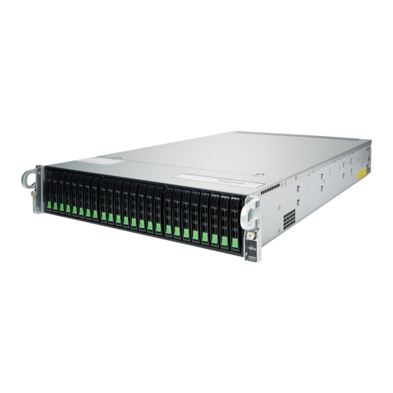
Appendix A 14.1 Mechanical overview 14.1.1 Server front Figure 159: Server front Front panel Up to 24 2.5-inch HDDs or SSDs or ID card with System ID label PCIe SSDs or dummy modules RX2450 M1 Upgrade and Maintenance Manual... -
Page 200: Server Rear
Appendix A 14.1.2 Server rear Figure 160: Server rear PCIe slot 1 (right slot of Ultra riser PCIe slot 4 (lower slot of riser module card) PCIe slot 2 (upper left slot of Ultra riser I/O panel card) PCIe slot 6 (lower left slot of Ultra riser PCIe slot 5 (slot of riser card right), card, only for PDUAL CP100) occupied by Add-on LAN card... -
Page 201: Server Interior
Appendix A 14.1.3 Server interior Figure 161: Server interior PSU (2x) CPUs with heat sink (2x) HDDs/SSDs System board Front panel Riser module 1 HDD backplane Add-on LAN card System fans (4x) Riser module 2 Main memory modules RX2450 M1 Upgrade and Maintenance Manual... -
Page 202: Connectors And Indicators
Appendix A 14.2 Connectors and indicators 14.2.1 System board 14.2.1.1 System board H12DSU-iN Onboard connectors H12DSU-iN REV: DESIGNED IN USA CPU2 CPU1 Figure 162: Connectors on system board H12DSU-iN Upgrade and Maintenance Manual RX2450 M1... - Page 203 Appendix A Pos. Print Description PSU2 Power connector for PSU 2 PSU1 Power connector for PSU 1 JSD1/2 Disk-On-Module Power Connector PWR1 Power connectors for the backplane PWR2 PWR3 PWR4 USB1 USB 3.0 Type A Header SATA8 SATA 3.0 connector SATA9 SATA 3.0 connector P1_NVME0/1...
- Page 204 Appendix A Pos. Print Description P2_NVME1 NVMe connector 1 / SATA 14-17 (CPU2) SATA14-17 P2_NVME2/3 NVMe connector 2/3 (CPU2) USB3/4 USB3/43.0 Front Side Pin Header GPU PWR1 Power connector for GPU 1 GPU PWR2 Power connector for GPU 2 JNCSI1 NCSI JIPMB1 IPMI card connector...
- Page 205 Appendix A Onboard indicators H12DSU-iN REV: DESIGNED IN USA CPU2 CPU1 Figure 163: Indicators on system board H12DSU-iN Indicator Status Description A - UID UID switch off blue on UID switch on BMC controller cannot be detected orproperly initiated. B - BMC Heartbeat green on BMC initialing.
-
Page 206: Server Front
Appendix A Indicator Status Description C - Power System power is not ready. green on System power is ready. 14.2.2 Server front 14.2.2.1 Indicators on the front panel Figure 164: Indicators on the front panel PSU failure indicator Drive activity indicator Power indicator Information indicator PSU failure indicator (1) - Page 207 Appendix A Power indicator (2) Status Description Power is being supplied to the PSUs and the system is operating normally. Drive activity indicator (3) Status Description flashing amber Activity on the HDD When only SAS or NVMe drives are installed, this indicator does not turn on. Information indicator (4) Status Description...
-
Page 208: Indicators On Hot-Plug Hdd / Ssd / Pcie Ssd Modules
Appendix A 14.2.2.2 Indicators on hot-plug HDD / SSD / PCIe SSD modules Figure 165: Indicators on an HDD / SSD / PCIe SSD module Activity indicator Status indicator Activity indicator (1) Status Description blue on SATA drive is being accessed. flashing blue SAS drive or NVMe drive is installed. -
Page 209: Server Rear
Appendix A Status Description green on NVMe device can be removed safely flashing amber at Attention state, do not remove NVMe drive. 1 Hz 14.2.3 Server rear 14.2.3.1 Connectors on the server rear Figure 166: Connectors on the server rear USB 3.0 connector (2x), transfer speed LAN connector (on Add-on LAN card), 5 Gbit/s... -
Page 210: Indicators On The I/O Panel
Appendix A 14.2.3.2 Indicators on the I/O panel Figure 167: Indicators on the I/O panel ID indicator ID indicator (1) Status Description blue on Identification has been activated locally to locate the server in a rack environment. flashing blue Identification has been activated using IPMI to locate the server in a rack environment. -
Page 211: Lan Indicators
Appendix A 14.2.3.3 LAN indicators Figure 168: LAN indicators Link indicator (IPMI) Activity indicator (GLAN) Activity indicator (IPMI) Link indicator (GLAN) Link indicator (1) Status Description No connection or data traffic at a transfer rate of 10 Mbit/s green on Data traffic at a transfer rate of 100 Mbit/s amber on Data traffic at a transfer rate of 1 Gbit/s... -
Page 212: Indicator On Hot-Plug Psu
Appendix A Link indicator (4) Status Description No connection or data traffic at a transfer rate of 10 Mbit/s green on Data traffic at a transfer rate of 100 Mbit/s orange on Data traffic at a transfer rate of 1 Gbit/s 14.2.3.4 Indicator on hot-plug PSU Figure 169: Indicator on hot-plug PSU... - Page 213 Appendix A 14.2.4 Acoustic indicators PEI Beep Codes Pre-EFI Initialization (PEI) - memory Initialization (bootblock) # of Description Action Beep ▶ Check if the memory module is Memory not installed installed. ▶ Check if the memory module is installed correctly. Recovery started Recovery procedure is initialized by jumper settings on the system board and...
- Page 214 Appendix A # of Description Action Beep ▶ Check for the correct password and try Invalid password again. Make sure that the caps lock key is deactivated. No Console Input Booting will continue. devices or Output Serial console redirection is considered devices are found a console output device if enabled.
- Page 215 Appendix A 14.3 Onboard settings JWD1 JBT1 H12DSU-iN REV: DESIGNED IN USA CPU2 CPU1 Figure 170: Position Jumper on system board H12DSU-iN Jumper Status Description Default (place to keep the jumper) Password Skip enabled JBT1 Clear CMOS This jumper setting will permanently delete the current BIOS password and apply default BIOS settings.
- Page 216 Appendix A Jumper Status Description Default JWD1 Watch Dog Disabled 14.4 Minimum startup configuration Field Replaceable Units (FRU) If the server does not start up or other problems occur, it may be necessary to take the system down to its most basic configuration in order to isolate the defective component.
- Page 217 Appendix A ▶ "Shutting down the server" on page ▶ "Disconnecting the power cord (AC PSU)" on page ▶ Take the system down to its minimum startup configuration. ▶ "Connecting the power cord" on page ▶ Connect a display to the server. ▶...
- Page 218 Appendix A Upgrade and Maintenance Manual RX2450 M1...
- Page 219 The following documents are available in this appendix: ● "Cable plan for FUJITSU Server PRIMERGY RX2450 M1 Reference Manual" ● "List of Released Adapters incl. Installation sequence and priority" ● "Screw list for FUJITSU Server PRIMERGY RX2450 M1 Reference Manual" RX2450 M1 Upgrade and Maintenance Manual...
- Page 220 Cable Plan(ver1.0) List of used cables Vendor Part number FUJITSU Part number Naming CBL-PWEX-0673 CA05973-7608 Backplane power cable CBL-SAST-1257-100 CA05973-7609 SATA cable1 CBL-SAST-1295-100 CA05973-7610 SATA cable2 CBL-SAST-0826 CA05973-7612 NVME cable CBL-0088L CA05973-7629 FAN cable to MB CBL-0318L CA05973-7630 FP adapter cable...
- Page 221 Disk Bay : Disk Bay Type is related to Cable Plan. Only HDD/SSD SATA SATA/SAS NVMe Raid configuration is allowed. Raid card is required.
- Page 223 Type1: Default Configuration without HBA and PRAID Disk configuration Max configuration 16x SATA HDD/SSD [Onboard] 4x PCIe SSD [Onboard]...
- Page 224 Mother Board FAN 1 (FAN-0166L4) FAN1 FAN5 FAN 5 (FAN-0166L4) FAN7 FAN 7 (FAN-0166L4) FAN8 FAN 8 (FAN-0166L4) JPW4 JPW1 JPW2 JPW3 JPW3 JPW4 JPW2 JPW5 Mother Board (MBD-H12DSU-IN) JPW6 (CA05973-7603) HDD Backplane SAS#1 P1_NVME0/1 SATA0-7 (BPN-SAS3-216A-N4) (CA05973-7604) SAS#2 P2_NVME0 SATA0-13 SAS#3 SAS#4 P2_NVME1 SATA14-17...
- Page 225 Mother Board Front Panel Adapter Module Board (MCP-290-82918-0V) (FPB-TB826-T) Mother Board (CA05973-7633) (CA05973-7628) (MBD-H12DSU-IN) (CA05973-7603) GPU cable(option) Slot1 GPU PWR1 GPU A100/A40/RTX A6000 Slot3 GPU PWR3 GPU A100/A40/RTX A6000 Mother Board (MBD-H12DSU-IN) (CA05973-7603) Slot1 GPU PWR1 GPU A10 Slot3 GPU PWR3 GPU A10...
- Page 226 Type2: Front 1x CP503i/EP520i Disk configuration 10 11 12 13 14 15 16 17 18 19 20 21 22 23 Onboard Onboard HBA or RAID PCIeSSD Controller Max configuration 12x SATA HDD/SSD [Onboard] 4x SATA HDD/SSD [Controlled by RAID/HBA] 4x SAS HDD or SATA HDD/SSD [Controlled by RAID/HBA] 4x PCIe SSD [Onboard]...
- Page 227 Mother Board FAN 1 (FAN-0166L4) FAN1 FAN5 FAN 5 (FAN-0166L4) FAN7 FAN 7 (FAN-0166L4) FAN8 FAN 8 (FAN-0166L4) JPW4 JPW1 JPW2 JPW3 JPW3 JPW4 JPW2 JPW5 Mother Board (MBD-H12DSU-IN) JPW6 (CA05973-7603) HDD Backplane SAS#1 P1_NVME0/1 SATA0-7 (BPN-SAS3-216A-N4) (CA05973-7604) SAS#2 P2_NVME0 SATA0-13 SAS#3 P1_NVME2/3 NVME#1...
- Page 228 Mother Board Front Panel Adapter Module Board (MCP-290-82918-0V) (FPB-TB826-T) Mother Board (CA05973-7633) (CA05973-7628) (MBD-H12DSU-IN) (CA05973-7603)
- Page 229 SAS cable(option) HDD Backplane (BPN-SAS3-216A-N4) (CA05973-7604) SAS#4 RAID card (EP 520i/ EP 540i/ EP580i/ CP503i) SAS#5 GPU cable(option) Slot1 GPU PWR1 GPU A100/A40/RTX A6000 Slot3 GPU PWR3 GPU A100/A40/RTX A6000 Mother Board (MBD-H12DSU-IN) (CA05973-7603) Slot1 GPU PWR1 GPU A10 Slot3 GPU PWR3 GPU A10...
- Page 230 The configuration for 16 slots RAID support(use RAID card x1) Disk configuration 10 11 12 13 14 15 16 17 18 19 20 21 22 23 Onboard Onboard HBA or RAID PCIeSSD Controller Max configuration 4x SATA HDD/SSD [Onboard] 12x SATA HDD/SSD [Controlled by RAID/HBA] 4x SAS HDD or SATA HDD/SSD [Controlled by RAID/HBA] 4x PCIe SSD...
- Page 231 Mother Board FAN 1 (FAN-0166L4) FAN1 FAN5 FAN 5 (FAN-0166L4) FAN7 FAN 7 (FAN-0166L4) FAN8 FAN 8 (FAN-0166L4) JPW4 JPW1 JPW2 JPW3 JPW3 JPW4 JPW2 JPW5 Mother Board (MBD-H12DSU-IN) JPW6 (CA05973-7603) HDD Backplane SAS#1 P1_NVME0/1 SATA0-7 (BPN-SAS3-216A-N4) (CA05973-7604) SAS#6 P1_NVME2/3 NVME#1 NVME#2 P2_NVME2/3...
- Page 232 Mother Board Front Panel Adapter Module Board (MCP-290-82918-0V) (FPB-TB826-T) Mother Board (CA05973-7633) (CA05973-7628) (MBD-H12DSU-IN) (CA05973-7603)
- Page 233 SAS cable(option) SAS#2 SAS#3 RAID card HDD Backplane (EP540i/ EP580i) (BPN-SAS3-216A-N4) SAS#4 (CA05973-7604) SAS#5 GPU cable(option) Slot1 GPU PWR1 GPU A100/A40/RTX A6000 Slot3 GPU PWR3 GPU A100/A40/RTX A6000 Mother Board (MBD-H12DSU-IN) (CA05973-7603) Slot1 GPU PWR1 GPU A10 Slot3 GPU PWR3 GPU A10...
- Page 234 Type3: Front 2x CP503i/EP520i or 1x EP540i/EP580i Disk configuration 10 11 12 13 14 15 16 17 18 19 20 21 22 23 Onboard Onboard HBA or RAID PCIeSSD Controller Max configuration 4x SATA HDD/SSD [Onboard] 12x SATA HDD/SSD [Controlled by RAID/HBA] 4x SAS HDD or SATA HDD/SSD [Controlled by RAID/HBA] 4x PCIe SSD [Onboard]...
- Page 235 Mother Board FAN 1 (FAN-0166L4) FAN1 FAN5 FAN 5 (FAN-0166L4) FAN7 FAN 7 (FAN-0166L4) FAN8 FAN 8 (FAN-0166L4) JPW4 JPW1 JPW2 JPW3 JPW3 JPW4 JPW2 JPW5 Mother Board (MBD-H12DSU-IN) JPW6 (CA05973-7603) HDD Backplane SAS#1 P1_NVME0/1 SATA0-7 (BPN-SAS3-216A-N4) (CA05973-7604) SAS#6 P1_NVME2/3 NVME#1 NVME#2 P2_NVME2/3...
- Page 236 Mother Board Front Panel Adapter Module Board (MCP-290-82918-0V) (FPB-TB826-T) Mother Board (CA05973-7633) (CA05973-7628) (MBD-H12DSU-IN) (CA05973-7603)
- Page 237 SAS cable(option) SAS#2 RAID card (EP 520i/ CP503i) SAS#3 HDD Backplane (BPN-SAS3-216A-N4) (CA05973-7604) SAS#4 RAID card (EP 520i/ CP503i) SAS#5 GPU cable(option) Slot1 GPU PWR1 GPU A100/A40/RTX A6000 Slot3 GPU PWR3 GPU A100/A40/RTX A6000 Mother Board (MBD-H12DSU-IN) (CA05973-7603) Slot1 GPU PWR1 GPU A10 Slot3 GPU PWR3...
- Page 238 Type4: Front 2x EP540i/EP580i Disk configuration Max configuration 16x SATA HDD/SSD [Controlled by RAID/HBA] 4x SAS HDD or SATA HDD/SSD [Controlled by RAID/HBA] 4x PCIe SSD [Onboard]...
- Page 239 Mother Board FAN 1 (FAN-0166L4) FAN1 FAN5 FAN 5 (FAN-0166L4) FAN7 FAN 7 (FAN-0166L4) FAN8 FAN 8 (FAN-0166L4) JPW4 JPW1 JPW2 JPW3 JPW3 JPW4 JPW2 JPW5 Mother Board (MBD-H12DSU-IN) JPW6 (CA05973-7603) HDD Backplane (BPN-SAS3-216A-N4) (CA05973-7604) P1_NVME2/3 NVME#1 NVME#2 P2_NVME2/3 NVME#3 NVME#4...
- Page 240 Mother Board Front Panel Adapter Module Board (MCP-290-82918-0V) (FPB-TB826-T) Mother Board (CA05973-7633) (CA05973-7628) (MBD-H12DSU-IN) (CA05973-7603)
- Page 241 SAS cable(option) SAS#1 SAS#2 RAID card (EP 540i / EP580i) HDD Backplane SAS#3 (BPN-SAS3-216A-N4) (CA05973-7604) SAS#4 SAS#5 RAID card (EP 540i / EP580i) GPU cable(option) Slot1 GPU PWR1 GPU A100/A40/RTX A6000 Slot3 GPU PWR3 GPU A100/A40/RTX A6000 Mother Board (MBD-H12DSU-IN) (CA05973-7603) Slot1 GPU PWR1...
- Page 242 Installation Vendor Description (Softwarepool) (Softwarepool) Adapter Comment Last change Controller Card - Fujitsu Technology PRAID EP580i S26361-F4042-L508(... HW-9574 7/30/2021 Fujitsu Technology PRAID EP540i S26361-F4042-L504(... HW-9573 7/30/2021 Fujitsu Technology PRAID EP520i S26361-F4042-L502(... HW-9571 7/30/2021 Controller Card - Broadcom PSAS CP503i S26361-F5792-L503(...
- Page 243 Screw Driver Item Photo Description Torque For example,Philips #2, Philips #1, Torx20 etc 10-SC51202N1SRT10101 Philips #2 TOP COVER 6.0+/-1kgf-cm #6-32X5L 10-SC51202N1SRT10101 Philips #2 RISER MODULE 6.0+/-1kgf-cm #6-32X5L 1U_REMOVABLE_PDB_NUT 10-SC8080200SRT10101 Manual fix, torque 9/32" wrench 1U_REMOVABLE_PDB_STDF 10-SC8080300SRT10102 undefined 10-SC8251400SRT10101 Philips #2 EAR_BKT 6.0+/-1kgf-cm I #6-32X4L...
- Page 244 8.0+/-1kgf-cm Hexagon 7mm SC829UT_GUIDE_PIN_NYLOK MCP-290-82915-0N 10-SC8251100SRT10101 Philips #2 MID_FAN_BKT 6.0+/-1kgf-cm #6-32X4L MID_FAN_BKT RISERBKT_R 10-SC5130100SRT10101 Philips #2 MID_FAN_BKT_G 6.0+/-1kgf-cm G #6-32X5L 10-SC8253200SRT10101 Philips #2 3.5+/-1kgf-cm I-T2 #6-32X5L 10-SC8251500SRT10101 RISERBKT_1 Philips #2 6.0+/-1kgf-cm I #6-32X4L RISERBKT_L RISERBKT_R 10-SC93310N1SRT10101 RISERBKT_2 #6-32X5L Philips #2 6.0+/-1kgf-cm (This screw is in the accessory box) RISERBKT_L RISERBKT_R...
- Page 245 RISERBKT_3 10-SC9733200SRT10101 Philips #1 6.0+/-1kgf-cm RISERBKT_L RISERBKT_R CP100 10-SC8253000SRT10101 RISERBKT_R Philips #2 6.0+/-1kgf-cm #6-32X3L 10-SC8250400SRC10101 Rack_Rail1 M4X6L Philips #2 7.0+/-1kgf-cm (This screw is in the accessory box) 10-SC5122400SRC10101 30.0+/-1kgf-cm Rack_Rail2 Philips #2 (This screw is in the accessory box) 10-SC5122800SRC10101 Rack_Rail3 (This washer is in the accessory box)
- Page 246 10-SC8260200SRC10101 Rack_Rail4 Not used in RX2450M1 - - (This screw is in the accessory box) 10-SC8253500SRT10101 8.0+/-1kgf-cm BPN1 Philips #2 B#6-32X6L...