
Related Manuals for Fujitsu PRIMERGY RX2540 M5


Summary of Contents for Fujitsu PRIMERGY RX2540 M5
- Page 1 Operating Manual - English FUJITSU Server PRIMERGY RX2540 M5 Operating Manual March 2019...
- Page 2 – The contents of this manual may be revised without prior notice. – Fujitsu assumes no liability for damages to third party copyrights or other rights arising from the use of any information in this manual. – No part of this manual may be reproduced in any without the prior written permission of Fujitsu.
- Page 3 Before reading this manual For your safety This manual contains important information for safely and correctly using this product. Carefully read the manual before using this product. Pay particular attention to the accompanying manual "Safety Notes and Regulations" and ensure that these safety notes are understood before using the product.
- Page 4 Please consult the sales staff of Fujitsu if intending to use this product for high safety use. Measures against momentary voltage drop This product may be affected by a momentary voltage drop in the power supply caused by lightning.
- Page 5 For more information on the usage and operation conditions of each available type of HDD, see the following internet address: http://jp.fujitsu.com/platform/server/primergy/harddisk/ Operating Manual RX2540 M5...
- Page 6 Operating Manual RX2540 M5...
-
Page 7: Table Of Contents
Content Introduction ......11 Notational conventions ....11 Before you start . - Page 8 Content Starting up ......59 Installation steps, overview ....60 Unpacking the server .
- Page 9 Content Operation ......81 Switching the server on and off ....81 Installing HDD/SSD modules .
- Page 10 Content Operating Manual RX2540 M5...
-
Page 11: Introduction
This operating manual is intended for those responsible for installing the hardware and ensuring that the system runs smoothly. It contains all the information you need to put your PRIMERGY RX2540 M5 into operation. To understand the various expansion options, you will need to be familiar with the fields of hardware and data transmission and you will require a basic knowledge of the underlying operating system. - Page 12 Introduction Operating Manual RX2540 M5...
-
Page 13: Before You Start
Documentation overview To get an overview on all documents for your server, see the following table. All documentation on PRIMERGY hardware and ServerView software is available online from the Fujitsu manuals server at: http://manuals.ts.fujitsu.com For Japan: http://www.fujitsu.com/jp/products/computing/servers/primergy/manual/ The complete PRIMERGY documentation set can also be downloaded as a DVD ISO image at: ftp://ftp.ts.fujitsu.com/images/serverview/manuals... - Page 14 Management (eLCM)" user guide Illustrated Spares catalog Spare parts identification and information system (not valid for Japan), available for online use or download (Windows OS) at http://manuals.ts.fujitsu.com/illustrated_sp ares or from the CSS component view of the ServerView Operations Manager Glossary...
- Page 15 Description "Returning used devices" Recycling and contact information, manual available online at http://ts.fujitsu.com/recycling, or as a "Service Desk" leaflet printed copy " サポー ト &サービ ス " for Japan Not applicable in Japan and other countries that have different regulations for recycling...
- Page 16 Before you start Operating Manual RX2540 M5...
-
Page 17: Product Description
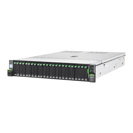
This section provides an overview of the server and information on the features of the PRIMERGY RX2540 M5 server. The PRIMERGY RX2540 M5 server is available as a rack model. Overview of the server Figure 1: Front side 3.5-inch HDDs (up to 8 HDDs) Figure 2: Front side 3.5-inch HDDs (up to 12 HDDs) - Page 18 Product description Figure 3: Front side 2.5-inch HDDs (up to 16 HDDs) Figure 4: Front side 2.5-inch HDDs (up to 24 HDDs) Pos. Component ID card Front panel module Space for LTO drive Space for HDDs (depending on the configuration) Operating Manual RX2540 M5...
-
Page 19: Features
– Expansion cards (not allowed in Japan) – Liquid cooling (not allowed in Japan) For more information on replacing these components, see the "FUJITSU Server PRIMERGY RX2540 M5 Upgrade and Maintenance Manual". CSS indicators on the front panel and I/O panel of the PRIMERGY server provide you with information if a CSS event arises. - Page 20 Product description System board The features of the system board are described in the "FUJITSU Server PRIMERGY RX2540 M5 Upgrade and Maintenance Manual". The setup possibilities are described in the "D3384 BIOS Setup Utility for FUJITSU Server PRIMERGY RX2540 M5 Reference Manual".
- Page 21 Product description Power supply unit (PSU) The server can be equipped with: – with up to two AC PSUs In its basic configuration the server has one PSU that adjusts automatically to any mains voltage in the range of 100 V - 240 V (AC PSU Platinum) or 200 V - 240 V (AC PSU Titanium).
- Page 22 "hides" the defective system components. The Prefailure Detection and Analysis (PDA) technology from Fujitsu analyzes and monitors all components that are critical for system reliability. A RAID controller supports different RAID levels and increase the availability and data security of the system.
- Page 23 ServerView Suite - Out-Of-Band Management). Server management Server management is implemented using the ServerView Operations Manager supplied and the PDA technology from Fujitsu. PDA reports the threat of a system error or overload at an early stage, allowing preventive measures to be taken.
- Page 24 (memory module, CPU, fan or expansion card) is not functioning properly. The Flash EPROM program supplied with the Fujitsu utilities supports a fast BIOS update. With the iRMC on the system board, the server can also be maintained and serviced remotely.
- Page 25 By combining these options, you can also achieve optimum protection for your system. A detailed description of the Security menu and how to assign passwords can be found in the "D3384 BIOS Setup Utility for FUJITSU Server PRIMERGY RX2540 M5 Reference Manual". Operating Manual...
-
Page 26: Connectors, Controls And Indicators
Product description Connectors, controls and indicators 3.3.1 Connectors on the server 3.3.1.1 Server front 3.5-inch HDD versions Figure 5: Connectors on the server front 3.5-inch version 2.5-inch HDD versions Figure 6: Connectors on the server front 2.5-inch version 2x USB 3.0 connectors 1x Front VGA (optional) Operating Manual RX2540 M5... - Page 27 Product description 12x 3.5-inch HDD version and 24x 2.5-inch HDD version For this version there is an USB 2.0 connector on the front panel on QRL instead of the two above mentioned USB3.0 connectors. Figure 7: Front panel on QRL 1x USB 2.0 connector Operating Manual RX2540 M5...
-
Page 28: Server Rear
Product description 3.3.1.2 Server rear Figure 8: Connectors on the server rear Serial connector COM1 Shared LAN connector (LAN1) (optional)* Management LAN connector 2x USB 3.0 connectors (for iRMC S5 server management function) Video connector (VGA) OCP module (optional, different variants) LAN connector (LAN2) The serial connector can be used as the standard interface or for... - Page 29 Product description Depending on the BIOS settings, the shared LAN connector may also be used as a management LAN connector. For more information, see the corresponding BIOS Setup Utility reference manual. Some of the devices connected require special software (e.g. drivers) (see documentation for the connected device).
-
Page 30: Controls And Indicators On The Server Front
Product description 3.3.2 Controls and indicators on the server front 3.3.2.1 Controls on the front panel Figure 10: Controls on the front panel module Figure 11: Controls on the front panel on QRL Operating Manual RX2540 M5... - Page 31 Product description Pos. Label Button Function Reboots the system. Press the reset button with a straightened end of a paper clip. RESET Reset button CAUTION! Risk of data loss! Used to troubleshoot software and device driver errors. Press the NMI button with a straightened end of a paper clip.
-
Page 32: Indicators On The Front Panel
Product description 3.3.2.2 Indicators on the front panel Figure 12: Indicators on the front panel module Figure 13: Indicators on the front panel on QRL Pos. Label Indicator Status Description The server has been highlighted using ServerView Operations indicator, blue on Manager, iRMC web interface or the see also ID button on the front panel for easy... - Page 33 Product description Pos. Label Indicator Status Description No critical event detected (CSS component). Prefailure event detected (CSS component). orange [CSS] For HDDs/SSDs, see also indicator "HDD/SSD prefailure detection" on page flashing CSS component failure detected. orange No critical event detected (non CSS component).
- Page 34 Product description Pos. Label Indicator Status Description – The server is switched off and connected to the mains (standby mode). – The server has been switched on but Power Cycle Delay settings delay it from turning on for a green on specified time.
- Page 35 For more information on the flashing blue flashing orange emergency flash of the iRMC firmware, see the "FUJITSU Server PRIMERGY RX2540 M5 Upgrade and Maintenance Manual". HDD/SSD prefailure detection Depending on your hardware configuration HDD/SSD prefailure detection will be supported.
-
Page 36: Indicator On The Odd
Product description 3.3.2.3 Indicator on the ODD ODDs may have an indicator or not. Figure 14: Example: Indicator on the ODD Pos. Indicator Status Description The ODD is inactive. Activity indicator green on The storage medium is being accessed. Operating Manual RX2540 M5... -
Page 37: Indicators On The Hot-Plug Hdd/Ssd Module
Product description 3.3.2.4 Indicators on the hot-plug HDD/SSD module Figure 15: Indicators on the hot-plug HDD/SSD module Pos. Label Indicator Status Description The HDD/SSD is inactive. Access indicator green on The HDD/SSD being accessed No HDD/SSD error detected. An HDD/SSD error has been detected. -
Page 38: Indicators On The Server Rear
Product description 3.3.3 Indicators on the server rear 3.3.3.1 Indicators on the I/O panel ID, CSS and Global Error indicators Figure 16: ID, CSS and Global Error indicators (visible through the chassis perforation) Operating Manual RX2540 M5... - Page 39 Product description Pos. Label Indicator Status Description The server has been highlighted using ServerView Operations indicator, blue on Manager, iRMC web interface or see also the ID button on the front panel for "iRMC- easy identification. related The server has been highlighted status flashing for easy identification using the...
- Page 40 An emergency flash of the iRMC firmware is in progress. For more information on the flashing blue flashing orange emergency flash of the iRMC firmware, see the "FUJITSU Server PRIMERGY RX2540 M5 Upgrade and Maintenance Manual". Operating Manual RX2540 M5...
- Page 41 Product description LAN indicators Figure 17: Indicators on the connection panel: LAN indicators (example LoM: PLAN EM 4x1GB T) Pos. Indicator Status Description A LAN connection has been green on established. link/transfer LAN is not connected. indicator flashing LAN data transfer is in progress. green yellow on Data traffic at a transfer rate of 1 Gbit/s.
- Page 42 Product description Indication of LAN connection supporting Energy Efficient Ethernet (EEE mode) To configure the EEE mode, it is necessary that the on board LAN or an add in LAN card supports this mode and the connected switch supports this mode as well.
-
Page 43: Indicator On Hot-Plug Psu
Product description 3.3.3.2 Indicator on hot-plug PSU Figure 18: Indicator on hot-plug PSU (AC PSU) Figure 19: Indicator on hot-plug PSU (DC PSU) Pos. Indicator Status Description flashing The server is switched off, but mains green voltage is present (standby mode). The server is switched on and operating green on properly. - Page 44 Product description Operating Manual RX2540 M5...
-
Page 45: Important Information
Important information In this chapter you will find essential information regarding safety when working on your server. Depending on your server or the installed options some information is not valid for your server. CAUTION! Before installing and starting up a server, please observe the safety instructions listed in the following section. - Page 46 Important information Before starting up During installation and before operating the server, observe the instructions ● on environmental conditions for your server. If the server is brought in from a cold environment, condensation may form ● both inside and on the outside of the server. Wait until the server has acclimatized to room temperature and is absolutely dry before starting it up.
- Page 47 Important information Always connect the server and the attached peripheral devices to the same ● power circuit. Otherwise you run the risk of losing data if, for example, the server is still running but a peripheral device (e.g. memory subsystem) fails during a power outage.
- Page 48 Important information The warranty is void if the server is damaged during installation or ● replacement of server expansions. Only set screen resolutions and refresh rates that are specified in the ● operating manual for the monitor. Otherwise, you may damage your monitor. If you are in any doubt, contact your sales outlet or customer service center.
- Page 49 Important information The battery used in this server may present a fire or chemical burn hazard if ● mistreated. Do not disassemble, heat about 100 °C (212F), or incinerate the battery. Replace the lithium battery on the system board in accordance with the ●...
- Page 50 Important information Do not pull on, press hard, or otherwise handle the CD/DVD/BD tray ● roughly. Do not disassemble the ODD. ● Before use, clean the ODD tray using a soft, dry cloth. ● As a precaution, remove disks from the ODD when the drive is not to ●...
- Page 51 Important information – Protect the disks from exposure to heat and direct sunlight. Laser information The ODD complies with IEC 60825-1 laser class 1. CAUTION! The ODD contains a light-emitting diode (LED), which under certain circumstances produces a laser beam stronger than laser class 1. Looking directly at this beam is dangerous.
- Page 52 Important information Do not touch any connectors or conduction paths on an ESD module. ● Place all the components on a pad which is free of electrostatic charge. ● For a detailed description of how to handle ESD modules, see the relevant European or international standards (EN 61340-5-1, ANSI/ESD S20.20).
-
Page 53: Energy Star
Important information If the server/rack is intended for permanent connection to the mains ● only an authorized specialist (electrician) is allowed to work. Please follow the regulation of each country. If the server is integrated into an installation that draws power from an ●... -
Page 54: Ce Conformity
Important information CE conformity The system complies with the requirements of European Regulations. Find the CE declaration on certificate portal: https://sp.ts.fujitsu.com/sites/certificates/default.aspx To open the CE declaration applicable for your system, proceed as follows: Ê Select Industry Standard Servers. Ê Select your model, e.g. Rack server. -
Page 55: Fcc Class A Compliance Statement
Consult the dealer or an experienced radio/TV technician for help. ● Fujitsu is not responsible for any radio or television interference caused by unauthorized modifications of this equipment or the substitution or attachment of connecting cables and equipment other than those specified by Fujitsu. The correction of interferences caused by such unauthorized modification, substitution or attachment will be the responsibility of the user. -
Page 56: Environmental Protection
Important information Environmental protection Environmentally-friendly product design and development This product has been designed in accordance with the Fujitsu standard for "environmentally friendly product design and development". This means that key factors such as durability, selection and labeling of materials, emissions, packaging, ease of dismantling and recycling have been taken into account. - Page 57 More information can be found at: http://ts.fujitsu.com/recycling Details regarding the return and recycling of devices and consumables within Europe can also be found in the "Returning used devices" manual, via your local Fujitsu branch, or at: http://ts.fujitsu.com/recycling Operating Manual RX2540 M5...
- Page 58 Important information Operating Manual RX2540 M5...
-
Page 59: Starting Up
Starting up CAUTION! Follow the safety instructions in chapter "Important information" on ● page Do not expose the server to extreme environmental conditions (see ● "Ambient conditions" on page 106). Protect the server from dust, humidity and heat. Ensure that the server is acclimatized for the time indicated in this ●... -
Page 60: Installation Steps, Overview
Starting up Installation steps, overview Ê First of all, carefully read the safety instructions in "Important information" on page 45 and following. Ê Transport the server to the place where you want to set it up. Ê Unpack the system, check the contents of the package for visible transport damage and check whether the items delivered correspond to the details on the delivery note, see "Unpacking the server"... - Page 61 Installation Manager" on page For more information on installing the server (remote or local), see the "ServerView Installation Manager" user guide at http://manuals.ts.fujitsu.com under x86 Servers - Software - ServerView Suite - Server Installation and Deployment. Installation without ServerView Installation Manager –...
-
Page 62: Unpacking The Server
Ê Remove all scratching protection foils from the front panel, HDD/SSD frames, Fujitsu and PRIMERGY logo, VGA dummy and ODD dummy in case they are still sticked to the server system. Operating Manual... -
Page 63: Installing The Server In The Rack
If several units are simultaneously extended out of the rack, there is a risk that the rack could tip over. Fujitsu rack systems The rack systems from Fujitsu support the installation of PRIMERGY servers: – PRIMECENTER rack – PRIMECENTER M1 rack –... - Page 64 The power is supplied via the multiple socket outlets fitted in the rack (not valid for Japan). The main features of Fujitsu rack systems are as follows: – rail systems that can be mounted without tools – support systems having a linear alignment feature to ensure that they can...
-
Page 65: Installing The Server In The Rack
Starting up 5.3.1 Installing the server in the rack CAUTION! At least two people are needed to position the server on the rack rails. (For Japan, see " 安全上のご注意 ".) For configurations below 32 kg: At least two people are needed to lift the server into the rack cabinet. - Page 66 Starting up Figure 21: Inserting the server into the rack rails Ê Fully extend the rack rails until they lock in place (1). The rack rails must click into place so that they can no longer be moved. Ê At a slight angle, lower the server onto the rear mounting point on the rack rails (2).
- Page 67 Starting up Figure 22: Sliding the server into the rack Ê Release the locking mechanism of both rails (1). Ê Push the server as far as it will go into the rack (2) until the quick-release levers engage (3). CAUTION! Be careful with your fingers.
-
Page 68: Connecting Cables
Starting up Connecting cables 5.4.1 Notes on connecting/disconnecting cables CAUTION! Always read the documentation supplied with the device you wish to connect. Never connect, or disconnect cables during a thunderstorm. Never pull on a cable when disconnecting it. Always take hold of the cable by the plug. -
Page 69: Connecting Devices To The Server
Starting up Information for ensuring electromagnetic compatibility All data and signal cables must have sufficient shielding. The use of cable type S/FTP Cat5 or higher is recommended. Use of unshielded or badly shielded cables may lead to increased emission of interference and/or reduced fault-tolerance of the device. -
Page 70: Connecting The Liquid Cooling (Lc) To The External Cooling Environment (Special Release)
Starting up 5.4.3 Connecting the liquid cooling (LC) to the external cooling environment (special release) A LC configuration is provided on special release request only. The quick connectors to connect the LC to the server system are on the rear of the server. -
Page 71: Connecting The Power Cord
A second PSU can be added to ensure a redundant power supply. If one PSU is defective, the other then guarantees unimpaired operation. Each PSU can be replaced during operation (see the "FUJITSU Server PRIMERGY RX2540 M5 Server Upgrade and Maintenance Manual"). -
Page 72: Using The Cable Clamp (Ac Psu)
Starting up 5.4.4.2 Using the cable clamp (AC PSU) You can secure the power cord with a cable clamp to ensure that the power cord cannot be disconnected from the server by mistake. The cable clamp is included in the accessories pack that is delivered together with the server. Figure 24: Using cable clamps Ê... -
Page 73: Connecting The Power Cord (Dc Psu)
Starting up 5.4.4.3 Connecting the power cord (DC PSU) Example DC PSU -48 V CAUTION! The DC PSU adjusts automatically to any power voltage in the range from -40.5 V - -57 V. You may only operate the server if its rated voltage range corresponds to the local mains voltage. - Page 74 Starting up Example HVDC PSU 380 V CAUTION! The HVDC PSU adjusts automatically to any power voltage in the range from 200 V – 380 V. You may only operate the server if its rated voltage range corresponds to the local mains voltage. Figure 26: Connecting the server to the DC voltage - example HVDC PSU 380 V Ê...
-
Page 75: Switching On The Server For The First Time
"Ambient conditions" on page 106. When operating the server out of the specified temperature range, the server may operate improperly and data loss may occur. Furthermore, Fujitsu cannot be held responsible for any related damage, malfunction, or loss of data, etc. -
Page 76: Configuring The Server With Serverview Installation Manager
When using the ServerView Installation Manager you can configure the onboard controller either before or during installation. Descriptions of operating systems not covered in the RAID controller manual are provided in the corresponding readme files under: http://www.fujitsu.com/global/services/computing/server/ia/driver/index. html For Japan: http://www.fujitsu.com/jp/products/computing/servers/primergy/downloa... -
Page 77: Configuring The Controllers
5.6.1.2 Installing the operating system For more information on installing the server, see the "ServerView Installation Manager" user guide at http://manuals.ts.fujitsu.com under x86 Servers - Software - ServerView Suite - Server Installation and Deployment. Ê Open this manual. Ê For the remote or local installation, follow the instruction in this manual and on the screen. -
Page 78: Configuring The Server Without Serverview Installation Manager
Starting up Configuring the server without ServerView Installation Manager 5.7.1 Configuring the server and installing the operating system 5.7.1.1 Configuring the onboard SAS/SATA controller Ê If applicable, configure the onboard SATA controller, see "Notes on configuring controllers" on page Ê If applicable, configure the SAS/SATA RAID controller with MegaRAID functionality, see "Notes on configuring controllers"... -
Page 79: Notes On Configuring Controllers
A separate utility is available to the controller for MegaRAID configuration. For more information, see the "SAS Software User’s Guide" (on the Fujitsu manuals server under x86 Servers - Expansion Cards - Storage Adapters - LSI Configuration Software). More information on modular RAID controllers is provided in the "Modular RAID Controller Installation Guide"... -
Page 80: Note On Operating System
Open the Windows operating system / Restoring the preinstalled environment For the procedure to open the Windows operation system or to restore the preinstalled environment, see the manuals on the Fujitsu manual download site (http://www.fujitsu.com/jp/products/computing/servers/primergy/manual/) or the attached manuals. Linux operating system support... -
Page 81: Operation
"Ambient conditions" on page 106. When operating the server out of the specified temperature range, the server may operate improperly and data loss may occur. Furthermore, Fujitsu cannot be held responsible for any related damage, malfunction, or loss of data, etc. - Page 82 Operation Switching the server on The AC connected indicator lights up green (standby mode) when the server is connected to the mains. It will take about 60 seconds until the server can be switched on. Ê Press the On/Off button. The server is switched on, performs a system test and boots the operating system.
- Page 83 Operation – Wake up On LAN (WOL) The server is turned on by a command via the LAN (Magic Packet™). – After power failure The server automatically reboots following a power failure (depending on the settings in the BIOS or in iRMC). –...
-
Page 84: Installing Hdd/Ssd Modules
Operation Installi ng HDD/SSD modules 6.2.1 Installing 3.5-inch HDD modules 6.2.1.1 Removing a 3.5-inch HDD dummy module Figure 27: Removing a 3.5-inch dummy module Ê Press both tabs together (1) and pull the dummy module out of its bay (2). CAUTION! Keep the dummy module for future use. -
Page 85: Installing A 3.5-Inch Hdd Module
Operation 6.2.1.2 Installing a 3.5-inch HDD module Figure 28: Opening the 3.5-inch HDD module locking lever Ê Pinch the green locking clip (1) and open the locking lever (2). Figure 29: Installing the 3.5-inch HDD module Ê Insert the HDD module into a drive bay and carefully push back as far as it will go (1). -
Page 86: Installing 2.5-Inch Hdd/Ssd Modules
Operation Configuring the RAID array, see the documentation of the RAID controller, used in your configuration, see section "Documentation overview" on page 6.2.2 Installing 2.5-inch HDD/SSD modules 6.2.2.1 Removing a 2.5-inch HDD/SSD dummy module Figure 30: Removing a 2.5-inch HDD/SSD dummy module Ê... -
Page 87: Installing A 2.5-Inch Hdd/Ssd Module
Operation 6.2.2.2 Installing a 2.5-inch HDD/SSD module Figure 31: Opening the 2.5-inch HDD/SSD module locking lever Ê Pinch the green locking clip (1) and open the locking lever (2). Figure 32: Installing the 2.5-inch HDD/SSD module Ê Insert the HDD/SSD module into a drive bay and carefully push back as far as it will go (1). -
Page 88: Installing A Second Psu
Operation Ê When using a RAID array, add the additional HDD/SSD to the RAID array. Configuring the RAID array, see the documentation of the RAID controller, used in your configuration, see section "Documentation overview" on page Installing a second PSU 6.3.1 Removing the dummy cover Figure 33: Removing the PSU dummy cover... -
Page 89: Installing A Psu
Operation 6.3.2 Installing a PSU Figure 34: Folding up the handle Ê Push the handle of the PSU halfway upward in the direction of the arrow. Figure 35: Installing a PSU Ê Push the PSU into its bay (1) as far as it will go until the release latch snaps in place. -
Page 90: Cleaning The Server
Operation Figure 36: Installing the cable tie Ê Only for AC-PSU: Push the cable clamp into the corresponding hole until it clicks in. Ê Connecting the power cord to the PSU, see section "Connecting the power cord" on page Ê If applicable, configure the redundant power supply. Cleaning the server CAUTION! Switch off the server and disconnect the power plugs from the properly... - Page 91 Operation Wipe the server and monitor casing with a dry cloth. If particularly dirty, use a cloth that has been moistened in a mild domestic detergent and then carefully wrung out. Operating Manual RX2540 M5...
- Page 92 Operation Operating Manual RX2540 M5...
-
Page 93: Troubleshooting And Tips
Ê Contact our customer service team. The meaning of the error message is explained in the documentation for the relevant components and programs, available online at http://manuals.ts.fujitsu.com. Power-on indicator remains unlit after you have switched on your device Cause Troubleshooting Power cable Ê... - Page 94 Troubleshooting and tips The system will not boot after installing a new HDD Cause Troubleshooting SAS configuration Ê Check the settings for the HDDs (SAS Device incorrect Configuration) and the additional settings in the SAS configuration menu. Screen remains blank Cause Troubleshooting Monitor is switched off Ê...
- Page 95 Troubleshooting and tips Server switches itself off Cause Troubleshooting Server Management Ê Check the error list of System Event Log in has detected an error ServerView Operations Manager or in the iRMC web interface, and attempt to eliminate the error. No mouse pointer displayed on screen Cause Troubleshooting...
- Page 96 Ê If the date and time are still wrong after the server discharged has been switched off and back on again, replace the lithium battery (see the "FUJITSU Server PRIMERGY RX2540 M5 Upgrade and Maintenance Manual") or contact our customer service team.
- Page 97 Ê Remove and reinstall the drive while the system is switched on. If the HDD/SSD continues to be shown as defective, then replace it (see the "FUJITSU Server PRIMERGY RX2540 M5 Server Upgrade and Maintenance Manual"). Operating Manual RX2540 M5...
- Page 98 RAID controller configuration program. For more information, see the "Integrated RAID for SAS User’s Guide" available online http://manuals.ts.fujitsu.com under x86 Servers - Expansion Cards - Storage Adapters - LSI SAS / SCSI RAID Contollers or in the "Modular RAID Controller Installation Guide"...
- Page 99 Troubleshooting and tips ODD cannot read data Cause Troubleshooting ODD cannot read data Ê Check to see whether the CD/DVD/BD is inserted properly. If the CD/DVD/BD is not inserted, correctly insert the disk so that the label is facing Ê Check to see whether the CD/DVD/BD is not dirty. If the CD/DVD/BD is dirty, wipe it in a radial way with a soft, dry cloth.
- Page 100 Troubleshooting and tips Operating Manual RX2540 M5...
-
Page 101: Technical Data
Please be forewarned. The data sheets for this server contain more technical data. The data sheets are available online at: http://www.fujitsu.com/fts/products/computing/servers/primergy For more information, see the Documents tab under e.g. Rack Servers. For Japan: http://www.fujitsu.com/jp/products/computing/servers/primergy... - Page 102 Technical data Interfaces Rear: 2 x USB 3.0 (not on 12x 3.5-inch Front: 2 x USB 3.0 HDDs and 24x 2.5-inch Internal: 1 x USB 3.0 HDD/SSD version) Rear: 2 x USB 3.0 (for up to 12x 3.5-inch Front: 1x USB 3.0 (on QRL) HDDs and 24x 2.5-inch Internal: 1 x USB 3.0 HDD/SSD version)
- Page 103 Technical data Onboard or integrated controllers RAID controller PSAS CP400i with "Integrated RAID" (IR) RAID levels 0 and 1 are supported for internal HDD configurations. PRAID EP4x0 (based on LSI SAS3108) SAS/SATA HDD/SSD up to 12 Gbit/s SAS, 6 Gbit/s SATA, 8 ports internal/external RAID level: 0, 1, 1E, 10, 5, 50, 6, 60 1/2/4 GB cache, optional FBU...
- Page 104 Technical data Slots Slot 1, 2: PCIe Gen3 x8 notched, up to 130 mm length, low profile (mechanical x8) Slot 3: PCIe Gen3 x24 up to 130 mm length, low profile (mechanical x24) Slot 4: PCIe Gen3 x16 up to 312 mm length (mechanical x16) Slot 5: PCIe Gen3 x8 notched, up to 312 mm length...
- Page 105 Technical data Drive bays HDD bay configuration Front: – up to 12x 3.5-inch HDD – up to 24x 2.5-inch HDD/SSD – up to 8x 2.5-inch HDD/SSD + 8x 2.5-inch PCIe Rear: – up to 4x 2.5-inch SAS HDD/SSD or PCIe SSD Accessible drive bay 1 x 5.25/0.5-inch for ODD drive (not on 12x 3.5-inch...
- Page 106 Technical data Ambient conditions All temperature ratings shown are valid for sea level. An altitude derating of 1°C per 300m to 3048 m is applicable. Environment class 3K2 EN 60721 / IEC 721 Part 3-3 Environment class 2K2 EN 60721 / IEC 721 Part 3-2 Temperature: Operation (3K2) 10 °C ...
- Page 107 Technical data Electrical data: 800 W Platinum Rated voltage range 100 V - 240 V Frequency 50 Hz - 60 Hz Max. rated current 9.0 A - 3.5 A Electrical data: 800 W Titanium Rated voltage range 200 V - 240 V Frequency 50 Hz - 60 Hz Max.
- Page 108 Technical data Compliance with standards Product safety and ergonomics International IEC 60950-1 2nd Edition am 1 + am 2 IEC 62368-1:2014 (Second Edition) Europe Safety EN 60950-1 2nd Edition EN 62368-1:2014 EN 62479 Ergonomics ISO 9241-3xx EN 9241-3xx EK1-ITB 2000:2018 USA / Canada CSA-C22.2 No.
- Page 109 Technical data Korea KN 32 / KN 35 CE marking to EU directives Europe Low Voltage Directive 2014/35/EU Electromagnetic Compatibility 2004/30/EU RoHS Compliance Europe EN 50581 Taiwan CNS 15663 CAUTION! This device meets the requirements of Class A CISPR 22/32. This device can cause radio interference in residential areas.
- Page 110 Technical data Operating Manual RX2540 M5...
-
Page 111: Warranty And Service
Warranty and service Warranty The warranty regulations can be found online at:http://manuals.ts.fujitsu.com under x86 Servers - Safety / Eco / Warranty For Japan: http://www.fujitsu.com/jp/products/computing/servers/primergy/support/ For the warranty regulations select " 製品保証ご案内 ( 無償修理期間 )" Service Telephone numbers of the local service partner can be found online at: http://ts.fujitsu.com/support/servicedesk.html... - Page 112 Warranty and service Operating Manual RX2540 M5...