Table of Contents
YA-1W/YA-1Z/YA-2E/YA-2G Series
Model No.
Before operating this product, please read the instructions carefully and save this manual for future use.
Please read the operating instructions of peripheral equipment together with it.
First of all, please read "Safety precautions".
English version is the original instructions.
Operating Instructions
Arc Welding Robot Controllers
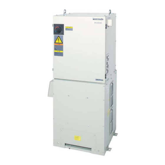
TAWERS WGH Ⅲ 450 A Type
- The Arc Welding Robotic System -
Model No.
YA-1WAR61T**
YA-1WAR61Y**
YA-1WAR61E**
YA-1WAR61U**
(TM-1400/TM-1100/TM-1600)
YA-1WAR81T**
YA-1WAR81Y**
YA-1WAR81E**
YA-1WAR81U**
(TM-1800/TM-2000)
YA-1ZAR81T**
YA-1ZAR81Y**
YA-1ZAR81E**
YA-1ZAR81U**
(TL-1800/TL-2000)
YA-2EAR81T**
YA-2EAR81Y**
YA-2EAR81E**
YA-2EAR81U**
(TS-800/TS-950)
YA-2GA261T**
YA-2GA261Y**
YA-2GA261E**
YA-2GA261U**
(LA-1800)
OM1305066E26
2010
Table of Contents

Related Manuals for Panasonic YA-1W Series


Summary of Contents for Panasonic YA-1W Series
- Page 1 Operating Instructions Arc Welding Robot Controllers YA-1W/YA-1Z/YA-2E/YA-2G Series Model No. Model No. YA-1WAR61T** YA-1WAR61Y** YA-1WAR61E** YA-1WAR61U** (TM-1400/TM-1100/TM-1600) YA-1WAR81T** YA-1WAR81Y** YA-1WAR81E** YA-1WAR81U** (TM-1800/TM-2000) YA-1ZAR81T** YA-1ZAR81Y** YA-1ZAR81E** YA-1ZAR81U** (TL-1800/TL-2000) YA-2EAR81T** YA-2EAR81Y** YA-2EAR81E** YA-2EAR81U** (TS-800/TS-950) YA-2GA261T** YA-2GA261Y** YA-2GA261E** YA-2GA261U** (LA-1800) TAWERS WGH Ⅲ 450 A Type - The Arc Welding Robotic System - ...
-
Page 2: Introduction
Introduction Introduction Thank you for purchasing our Panasonic arc welding robot For operation of the controller, please refer to the operating TAWERS series. This manual is the Operating Instructions instructions of “Teach Pendant for Arc Welding Industrial of robot controllers. -
Page 3: Table Of Contents
6.1.1 Spare emergency stop input ...... 31 Table of Contents 6.1.2 External emergency stop input ....32 6.1.3 Door stop input........... 32 6.1.4 Protective stop 1 input ....... 33 Introduction ......... 2 6.1.5 Protective stop 2 input ....... 33 6.1.6 External enabling input ...... -
Page 4: Safety Precautions
Safety Precautions 1.Safety Precautions Please read the “Safety manual” (separate volume) for detail safe handling. In case of using the product in a system, please also read the operating instructions of peripheral equipment. Signal Words and Safety Symbols Signal Words Safety Symbols Indicates a potentially hazardous WARNING... - Page 5 (5) Do not conduct welding at a site where degreasing, breakdown. cleaning or spraying is performed. Conducting welding (1) Contact Panasonic sales representatives for repair work. near the area where any of these types of work is per- (2) As for inspection of the inside the product if needed, formed can generate toxic gases.
- Page 6 Safety Precautions CAUTION (2) In case of using a torch cable with the resin liner, Rotating Parts straighten the torch cable and reduce the preset feed amount (current) to half or less before applying the Rotating parts can cause injury. wire inching.
-
Page 7: Specifications
Remodeling and/or modifying this product not in accordance with the manufacturers specification then this declaration will loose its validity. Authorised Representative: Panasonic Testing Centre Panasonic Marketing Europe GmbH Winsbergring 15, 22525 Hamburg, Germany The robot is designed in accordance with the following safety regulations and standard applied in the US and Canadian markets. -
Page 8: Technical Data
Specifications 2.2 Technical data 2.2.1 Structure and control method Item Specifications Structure and IP class Closed box type, IP32 or equivalent Cooling method Indirect air cooling (Circulating internal air), Direct air cooling (Welding power supply) Input power source 3-phase, 200 VAC ±20 VAC, 30.5 kVA (28 kW), 50/60 Hz ± 2 % (T/Y specifications only: Switchable to 220 VAC.) Maximum current: 246 A/5.6 ms(during servo ON) Grounding... -
Page 9
Specifications Dimensions T / Y spec. U spec.
4xφ14 (Unit: mm) (Unit: mm) E spec. 138: Other than LA-1800 178: LA-1800 4xφ14 (Unit: mm) OM1305066E26... -
Page 10: Inputs, Outputs And Communications
Specifications 2.3 Inputs, outputs and communications Items Input and output Specifications 1. Start 2. Hold Input 3. Error release 4. Teaching mode 5. Operating mode 6. Servo ON Status I/O 1. Running 2. Hold status 3. Error 4. Operating mode Output 5. -
Page 11: Specifications Of Digital Welding
Specifications 2.4 Specifications of digital welding Item Specifications Built-in welding power source type YA-1TD451T00 Welding method , MAG, Stainless steel MIG, Pulsed MAG/MIG Control method Inverter Max. no-load voltage 65 VDC Output current adjustable range 30 - 450 ADC Output voltage adjustable range 12 - 42 VDC Rated duty cycle (10 min. -
Page 12: Teach Pendant
Specifications 2.6 Teach Pendant Item Specifications Model number AUR01060 Environmental protection class IP42 or equivalent Display 7 inches wide TFT color graphic LCD Memory in TP IC memory SD memory card slot 1 slot USB 2.0 port 2(Hi-Speed: not supported), Bus power: 150 mA Enabling switch 3 points action Emergency stop switch... -
Page 13: Operation Box
Specifications 2.7 Operation Box T / Y spec. Optional E / U spec. Standard Item Specifications Environmental protection class IP40 or equivalent “AUTO mode” switch 1 (Connect to the “PNL” connector of the sequencer card.) Emergency stop switch 1 (Mechanical self-holding type. Connect to the “PNL” connector of the safety card.) Software If the operation box is purchased as an optional unit, the initial setup by... -
Page 14: Accessories For The Controller
Specifications 2.8 Accessories for the controller Repair parts order Safety Description Part number Q’ty Note number part TP hook AKC41237 AKC41237 For Teach Pendant TM14-1L500 YAB47 Ball chain 2 pcs/set AS6-SK-132 YAB178 1 set Mode select switch key Fuse (12 A anti-rush type) CES14-12AN2 YABD264 Fuse (8 A anti-rush type) -
Page 15: Connecting Cable (Sold Separately)
Two pieces of ground cable; AWC42164LN (5 m in length, 14 mm in sectional area (AWG6)) are included in the connect- ing able unit. Note • For other cable lengths, please consult Panasonic representatives. • Install manipulator and controller so that the distance between two is 30 m or shorter. -
Page 16: Transportation
Hook the wires to the provided eyebolts. About eyebolts Eyebolts are important safety parts. When they are lost or broken, purchase Panasonic genuine eyebolts for your safety. (3) In case it is necessary to use folk lift for transportation, pack and fix the controller in the transportation package before moving it. -
Page 17: Installation
Installation 4. Installation CAUTION The installation shall be made by qualified installation personnel and should conform to all national and local codes. 4.1 Choosing an installation site • Locate indoors with ambient temperature 0 °C to 40 °C. • IP code •... - Page 18 Installation (2) Installation method Fix the fixing plates of the controller to the ground or bedplate with M12 anchor bolts. (3) Teach pendant Hook the teach pendant on the provided TP hook. Hook for teach pendant TP hook should be installed outside of both the safety fence and the work envelope of the manipulator so as to prevent possible danger due to mode change inside the safety fenced area.
-
Page 19: Connection
Connection 5. Connection CAUTION The installation shall be made by qualified installation personnel and should conform to all national and local codes. 5.1 Connecting the controller to the manipulator 5.1.1 Connecting cable for the manipulator (1) Connect the motor cable and RE cable to the connec- tors for controller and manipulator respectively. -
Page 20: Connecting Cables For The Built-In Welding Power Source
Connection 5.1.2 Connecting cables for the built-in welding power source (1) Connect the output cable (customer preparation) from welding power source to the output terminal (-) for “BASE METAL” with attached M8 bolt. (Recom- mended clamping torque: 10.1 N•m-13.4 N•m) Terminal cover (2) Connect the welding power cable to the output termi- nal (+) for “TORCH”... -
Page 21: Connecting Teach Pendant
Connection 5.2 Connecting teach pendant Note Teach pendant Do not bend the TP cable near the connector and connect it to the controller. Otherwise, connecting pins may be damaged. TP cable Teach pendant Connect the TP cable to the connector of the teach pen- dant. -
Page 22: Connection Of Ground Wire
Connection 5.3 Connection of ground wire CAUTION Provide grounding to the protective earth terminal (PE) of the controller exclusively. Check the grounding work before operation. 5.3.1 Grounding Two 14 mm (AWG6) Green/yellow wires are supplied for Grounding Size of protective grounding. -
Page 23: Connecting Primary Power Source
Connection 5.4 Connecting primary power source 5.4.1 Wiring primary power cable Input power Cable size capacity 3-phase, 200 VAC 30.5 kVA 14 mm or more (28 kW) AWG6 or more (1) Be sure to provide no-fuse breaker (earth leakage breaker) or switch with fuse of specified capacity for each controller separately. -
Page 24: Wiring Primary Cables (For T*/Y* Specification)
Connection 5.4.2 Wiring primary cables (For T*/Y* specification) * the input power cable is customer preparation. (1) Remove the cover of the terminal box. (four M4 screws) Pass input power cables through the cord lock and then connect it to the input terminals. ... -
Page 25: Wiring Primary Cables (For E*/U* Specification)
Connection 5.4.3 Wiring primary cables (For E*/U* specification) * the input power cable is customer preparation. (1) Remove the cover of the breaker box. (four M4 screws) Pass input power cables through the cord lock and then connect it to the breaker. ... -
Page 26
Connection ( ) Loosen the four screws that hold the rack. Then open the rack. Rack opening direction
(4) Disconnect the primary side harness connector “200 VAC” of the transformer (UTU5315) located at Transformer the back of the rack of the controller from the connector UTU5315 “200 VAC”... -
Page 27: Door Handle
Connection 5.4.5 Door handle Normally the door handle is in the ON state during opera- tion. The door handle is used to turn ON/OFF the switch. Note • Allow 3 seconds interval after turning off the door handle and before back ON again. the alarm “Accidental If the interval is not long enough, power failure is detected.”... -
Page 28: Lock Switches With Padlock
Connection 5.4.6 Lock switches with padlock 1) Lock the door handle switch Use a padlock (customer preparation) to lock the door handle at the OFF position. Hasp part (a) Set the door handle to the OFF position. for padlock (b) Push the end of the handle, then the hasp for a padlock comes out. -
Page 29: Connecting And Control Method Of External Device
Connection 5.5 Connecting and control method of external device CAUTION Observe the following instructions in case of connecting external equipment. Apply a radio shield wire as I/O connecting cable between an external device and robot I/O circuit in order to protect the controller from noise. ... -
Page 30: Using Noise Filter Unit
• Check if the clamp filter is attached to the input/output signal cable. • Disconnect all input/output signal wires and then check if the above phenomena still occur. If the same error occurs, please consult your local Panasonic distributor. OM1305066E26... -
Page 31: Safety I/O Specifications
Safety I/O Specifications 6. Safety I/O Specifications CAUTION The product is delivered in emergency stop state. (Open Installation input) Confirm total safety of robot system and then short-circuit the external emergency stop input after the completion of the installation and start-up of the system. CAUTION About safety circuit •... -
Page 32: External Emergency Stop Input
Safety I/O Specifications 6.1.2 External emergency stop input (1) An input terminal to turn off the servo power of the manipulator from an external device. Emergency stop switch (2) Prepare a switch with two normally closed contacts. Emergency Connect one set of contacts between “EXTEMG1+” stop input and “EXTEMG1-”, and the other set between (Normally closed) -
Page 33: Protective Stop 1 Input
Safety I/O Specifications 6.1.4 Protective stop 1 input If the terminal is opened, driving force for all robot axes is stopped in terms of hardware, which stops all operation parts at once. If the terminal is short-circuited, the safety circuit goes into the ready-to-operate state in terms of hardware. -
Page 34: Input Of The Safety Circuit
Safety I/O Specifications 6.1.7 Input of the safety circuit Spare emergency stop (Short-circuited at the shipping from the factory.) Panel emergency stop (With operation box.) Teach pendant emergency stop switch Protective stop1 (Short-circuited at the shipping from the factory.) Teach pendant Enabling switch For Cooperative robot1 (Short-circuited at the... -
Page 35: Emergency Stop Output
Safety I/O Specifications 6.1.8 Emergency stop output An output terminal to output the emergency stop state. (No-voltage relay contact output, Contact ratings: 5 A, 30 VDC, minimum load 100 mA 5 VDC) Open the terminals in an emergency state. There are four kinds of emergency stop outputs as follows How connectors 1 Emergency stop output “OUTMD0”... - Page 36 Safety I/O Specifications Short connectors and emergency stop The following show the relationships between emergency < Safety card > stop input type and emergency stop output when each OUTMD0 connector is shorted. OUTMD1 OUTMD2 OUTMD3 Note OUTMD4 OUTMD3 is factory short-circuited at shipment. OUTMD5 OUTMD6 “Emergency stop output...
-
Page 37: Other Safety Input/Output
Safety I/O Specifications 6.2 Other safety input/output Ensure a safe work environment by using the safety I/O equipped with the safety card. 6.2.1 Safety holder input Input terminals for safety holder cable, which is not included in the safety circuit. The input is always monitored by software. -
Page 38: Terminal Location Of The Sequencer Card38
External Control Signal Connection 7. External Control Signal Connection 7.1 Terminal location of the sequencer card Note Specifications Part number Output type • Allocation of User I/O terminals vary with start method. T / Y / U ZUEP5789 Open collector (NPN) •Terminals marked with ZUEP5826 Open collector (PNP) -
Page 39: External Control Signal Connection38
External Control Signal Connection Sequencer card COM terminal for I/O Terminal or connector Application Common. 24 VDC power supply for maintenance (T/Y/U spec.) Maintenance use. U24V (E spec.) 24 VDC input for I/O 7.2 Serial interface The backplane card is provided with serial connectors to connect optional units and/or welding power source. -
Page 40: I/O Terminal Equivalent Circuit
External Control Signal Connection 7.3 I/O terminal equivalent circuit Spec. Input terminal equivalent circuit +24 VDC • To receive no-voltage ON/OFF contact signal from an external equipment. • External relay contact to be connected... 1 ohm or less, Chattering ..10 ms or less •... -
Page 41: Auto Start Settings
External Control Signal Connection 7.4 Auto start settings For details of settings and usage of the auto start, please refer to the operating instructions (Teach pendant for arc welding industrial robots.) 7.5 Status IN/OUT Dedicated input/output terminals to send signals when the robot is in specified state or to change robot status according to the signal received. -
Page 42: Status Output
External Control Signal Connection 7.5.2 Status OUTPUT Status OUTPUT Description Alarm output • The signal is output when the robot goes into an alarm condition. (At that time servo power is turned OFF) • Unless power is turned OFF, the output signal remains in ON state. Error output •... -
Page 43: Flowchart Of Status Outputs
External Control Signal Connection 7.6 Flowchart of Status Outputs 7.6.1 Operating and Holding output AUTO mode ON command is kept after completing PRG if OFF command is not executed ON command ON command OFF command Restoration Output terminal (Setting-HOLD:OFF, EMG STOP: OFF) ON command OFF command ON command... -
Page 44: Emergency Stop 1
External Control Signal Connection 7.6.3 Emergency stop 1 The following chart shows output terminal status to the emergency stop operation when it is set to the safety PCB connector OUTMB1. Power ON Power OFF AUTO mode ON command is kept after completing PRG ON command If OFF command is not executed. -
Page 45: Error Output
External Control Signal Connection 7.6.5 Error output AUTO mode ON command OFF command OFF command ON command Restoration Output terminal (Setting - HOLD: OFF, EMG STOP: OFF) ON command OFF command OFF command ON command Restoration Output terminal (Setting - HOLD: LOCK, EMG STOP: OFF) OFF command ON command ON command... -
Page 46: External Interface, External Memory
Open the cover at the bottom of the teach pendant to access the SD memory card slot. Open the cove and attach the memory card to it to use. SD memory card Recommended product: (Product of Panasonic) Part No.: RP-SDL series Cover It supports SD memory (maximum capacity 2 GB) and SDHC memory (maximum capacity 32 GB). -
Page 47: Welding Voltage/Current Monitor
External Control Signal Connection 7.9 Welding voltage/current monitor In case of using welding voltage/current monitor function, use the provided welding voltage/current monitor terminals. Connecting to the monitor terminals (1) Remove the terminal cover at the lower part of the con- troller front panel. -
Page 48: Maintenance And Inspection
Every 10 000 hours (or every fifth year) inspection contract with our company, our periodical inspections will start with a 2 000-hour (annual) inspec- tion. Note Inspection of the product is available as fare-paying ser- vice. For details, please contact Panasonic representa- tives. OM1305066E26... -
Page 49: Daily Check
“Temperature error”. In that case, clean the cooling fan. (If the error recurs after cleaning the cooling fan, please consult Panasonic representatives.) Filters at both (L/R) sides (4 pcs.) ... -
Page 50: Periodical Check
Maintenance and Inspection Inspections after turning on the power Check to confirm that no personnel are present within the robot work CAUTION envelope before turning on the power. Parts Item Service Remarks After turning on the servo If not, power, the servo power goes •... -
Page 51: Precautions For Withstand Voltage Test And Insulation Resistance Measurement
8.4 Precautions for withstand voltage test and insulation resistance measurement This product uses semiconductor components such as transistor. Executing withstand voltage test or insulation resistance measurement casually may cause serious phys- ical injury or mechanical failure. In case of necessity, con- tact our sales distributors or Panasonic representatives. OM1305066E26... -
Page 52: Disposal Of This Product
Disposal of this product 9. Disposal of this product After disposal of this product, data in the controller might go to third parties. To prevent this, perform All Clear in Memory clear menu before disposal. For details, refer to “Operating Instructions [Operation]”. OM1305066E26... -
Page 53: Repair Parts List
Repair Parts List 10. Repair Parts List 10.1 Controller E spec. OM1305066E26... - Page 54 Repair Parts List Repair part order Safety Description Part number Q’ty Note Class number part Anti-surge Parts AEB41080 AEB41080 T / Yspec. B32AA3P30WAR YAB112 Breaker U spec. MTNC000040AA MTNC000040AA MTNC000024AA MTNC000024AA E spec. Handle BZ6V10D YAB113 2 pcs/set, Terminal cover BW9BTAAS3W YAB114 Attach to the breaker...
- Page 55 C: Important electric parts. (*2) Eyebolts are important safety parts. When they D: Parts rather long replacement cycle. are lost or broken, purchase Panasonic genuine eyebolts for your safety. List of fuses (Safety parts) Installation...
-
Page 56: Teach Pendant
Repair Parts List 10.2 Teach pendant OM1305066E26... - Page 57 Repair Parts List Repair parts Safety Description Part number Q’ty Note Class order number part Case body AKH41014 AKH41014 Dial AKC31006 AKC31006 AKC31061 AKC31061 Jog cover AKC31060 AKC31060 Cover Trigger AKC31009 AKC31009 Lever 1 AKC31002 AKC31002 Lever 2 AKC31003 AKC31003 AKC41238 AKC41238 TP hanger...
-
Page 58: Operation Box
Repair Parts List 10.3 Operation Box T / Y spec. Optional E / U spec. StandardA: Consumable parts, rather short replacement cycle. B: Assemblies and parts of high frequency in motion. C: Important electric parts. D: Parts rather long replacement cycle. Repair parts Safety Description... -
Page 59: Critical Raw Material (Crm) List
Critical Raw Material (CRM) List 11. Critical Raw Material (CRM) List Description Part number Note Light Rare Earth Elements Motor TS4602N3030 Included in feeder (50 W). TS4606N3337 Included in feeder (100 W). TS4604N3022 Included in feeder (150 W). MTNM000185AA Included in feeder (200 W). OM1305066E26... -
Page 60: Circuit Diagram
Circuit Diagram 12. Circuit Diagram 12.1 Controller 1 OM1305066E26... -
Page 61: Controller 2
Circuit Diagram 12.2 Controller 2 OM1305066E26... -
Page 62: Welding Power Source
Circuit Diagram 12.3 Welding power source OM1305066E26... -
Page 63: Label Location
Label location 13.Label location 13.1 Location of labels Caution label Warning label (Y spec.) ANT41192 Warning label Caution label UNT00002 Type label ANT41505 (U spec. only) ANT41693(U spec.) ANT41228 (Y spec.) Windows CE Type label License Caution label ANM3**** Caution label WSANM00*** ANT30022 ANT41180... - Page 64 Label location • Only for U specifications Warning label UNT00002 Caution label Warning label WSANT00059 WSANT00053 Caution label Warning label WSANT00051 UNT00002 OM1305066E26...
- Page 65 Label location Only for E specifications (Other than LA-1800) • Only for E specifications (LA-1800) • OM1305066E26...
-
Page 66: Labels
Label location 13.2 Labels(LA-1800 U spec. only) (*Y spec. only) Smart Factory Solutions Co., Ltd. 2-7 Matsuba-cho, Kadoma City, Osaka 571-8502, Japan (*E spec. - Page 67 Label location < Warning label - WSANT00214 > < Warning label - ANT30022 > < Caution label - WSANT00052> < Warning label - WSANT00048 > < Caution label - WSANT00050 > (U spec. only) (U spec. only) (U spec. only) <...
- Page 68 Label location < Warning label - UNT00002 > < Caution label - ANT41505 > < Caution label - ANT41444 > < Caution label - ANT41366 > < Caution label - ANT40119 > < Warning label - ANT41228 > < Caution label - ANT41542 > <...
- Page 69 Label location < Warning, Caution label -ANT32063 > < Caution label - ANT41589> < Caution label - WSANT00199 > (U spec. only) (U spec. only) (U spec. only) < Caution label - WSANT00054> (U spec. only) < Caution label - ANT41588> (U spec.
- Page 70 Label location < Caution label - WSANT00055> < Warning label - ANT32065> (U spec. only) (U spec. only) < TUV mark - WSANH00048 > < Warning label - DNH00603> (U spec. only) (U spec. only) < Caution label - WSANT00029> <...
- Page 71 OM1305066E26...
- Page 72 Panasonic Smart Factory Solutions Co., Ltd. 2-7 Matsuba-cho, Kadoma City, Osaka 571-8502, Japan © Panasonic Smart Factory Solutions Co., Ltd. 2013 Printed in Japan OM1305066E26...