Table of Contents
Modular High Speed Placement Machine CM202
Maintenance Manual
Thank you for purchasing CM202, the modular high speed placement machine.
Before placing the machine in service, be sure to read the instruction manual for
proper usage.
After that, store it carefully and it if necessary.
Operating Instructions
Model No.
KXF-4U4C
KXF-D24C
KXF-E54C
(2/2)
4U4C-E-MMAB-0010
Table of Contents

Related Manuals for Panasonic CM202 Series


Summary of Contents for Panasonic CM202 Series
- Page 1 Modular High Speed Placement Machine CM202 Operating Instructions KXF-4U4C Model No. KXF-D24C KXF-E54C Maintenance Manual (2/2) Thank you for purchasing CM202, the modular high speed placement machine. Before placing the machine in service, be sure to read the instruction manual for proper usage.
- Page 3 This machine shall be operated by professional, specially trained operators. It shall not be operated by non-professional, not specially trained operators. For the training coursed you, make contact with Panasonic Factory Solutions Co., Ltd., PFAE or PIEL.” WARNING DO NOT ALLOW ANY PERSON WHO HAS NOT RECEIVED SPECIAL TRAINING TO OPERATE THE MACHINE.
- Page 4 SPECIFICATIONS Model Item 0 ° ° °) a l i 1 “ ” a 1 “ ” n ∗ ∗ ∗ ∗ ∗ 1 ± ± ± × × × × × × × × 2 ∗2 ∗2 ∗2 ∗2 ∗ °...
- Page 5 ORGANIZATION OF MANUALS This machine is accompanied by four manuals (CM201-DU, CM202-DU, CM202-DHU: five manuals). They are classified into three types (CM201-DU, CM202-DU, CM202-DHU: four types). Use each manual according to the working purpose. The production data of the line including this machine are programmed on PT. Refer to the instruction manuals accompanied with PT.
- Page 6 = MEMO = 4U4C-E-MMA00-B01-00...
- Page 7 Maintenance O N S C A U T I Manual Y P R E A N C E S A F E T I N T E N A R M A R E G U L R A M E T I N E P A R O R M A C H...
-
Page 8: Table Of Contents
SAFETY PRECAUTIONS ..............REGULAR MAINTENANCE Chapter Outline of Maintenance ................1-2 1-1-1 Checking the Operating Period, Contents and History Information ....1-2 1-1-2 Maintenance Motions ..................1-5 1-1-3 Regular Check Items for Period ................1-6 1-1-4 Regular Check Items for Each Unit ..............1-8 1-1-5 Machine Information .................. - Page 9 1-7-5 Tape Feeder Base : Replacing the Air Cylinder ..........1-85 1-7-6 Color Touch Panel : Replacing the Back Light ..........1-85 Check Every 12000 Hours (Once Two Years) .......... 1-86 1-8-1 Transfer Head : Replacing the valve (For the Vacuum Change) ...... 1-86 1-8-2 XY Unit : Replacing (Replacing Kit) the Valve (For Selecting the Nozzle, For the Cylinder) .
- Page 10 SOLUTIONS FOR ERROR Chapter Error Messages (Error List) ................ 3-2 3-1-1 Use of Error Message List ...................3-2 3-1-2 Errors during PT Network ..................3-2 3-1-3 Errors during Self-diagnosis ................3-3 3-1-4 Single Stop Error ....................3-4 3-1-5 Emergency Stop Error ..................3-4 Check and Solutions ..................
- Page 11 I/O MAP Appendix LOAD WIRING DIAGRAM Appendix LOAD WIRING DIAGRAM LOAD WIRING DIAGRAM (FEEDER PART) LOAD WIRING DIAGRAM (HEAD PART) LOAD WIRING DIAGRAM (CONVEYOR WIRING) LOAD WIRING DIAGRAM (EXTENSION CONVEYOR 1) LOAD WIRING DIAGRAM (EXTENSION CONVEYOR 2) LOAD WIRING DIAGRAM (ONLY FOR DHU SPECIFICATIONS) CONTROL BOX Appendix CPU BOX...
- Page 12 = MEMO = 4U4C-E-MMA00-A02-01...
- Page 13 SAFETY PRECAUTIONS Be sure to observe The precautions that must be observed in order to prevent injury to the user or another person, or damage to property, are as follows. The degree of danger or injury resulting from incorrect use due to failure to read an indica- tion is classified and described as follows.
- Page 14 SAFETY PRECAUTIONS Be sure to observe DANGER DO NOT TOUCH AC- DO NOT OPEN THE TIVE PART WHEN COVER WHEN OPER- OPERATING. ATING. You will have serious injury if You will have serious injury if you touch the active part. you touch the active part inside.
- Page 15 SAFETY PRECAUTIONS Be sure to observe WARNING If you sense any danger or abnormality, press an emergency stop button to stop the machine. If you continue to operate the machine in a dangerous or abnormal state, a breakdown or an accident will occur.
- Page 16 SAFETY PRECAUTIONS Be sure to observe WARNING If you sense any danger or abnormality, press an emergency stop button to stop the machine. If you continue to operate the machine in a dangerous or abnormal state, a breakdown or an accident will occur.
- Page 17 SAFETY PRECAUTIONS Be sure to observe WARNING If you sense any danger or abnormality, press an emergency stop button to stop the machine. If you continue to operate the machine in a dangerous or abnormal state, a breakdown or an accident will occur.
- Page 18 SAFETY PRECAUTIONS Be sure to observe WARNING Observe the following items before placing your hand or other part of your body in an active part of the machine in order to feed production material, change machine set-up, or adjust machine settings. You may be injured if the machine is actuated.
- Page 19 SAFETY PRECAUTIONS Be sure to observe WARNING Observe the following items before placing your hand or other part of your body in an active part of the machine in order to feed production material, change machine set-up, or adjust machine settings. You may be injured if the machine is actuated.
- Page 20 SAFETY PRECAUTIONS Be sure to observe WARNING Observe the following items before placing your hand or other part of your body in an active part of the machine in order to feed production material, change machine set-up, or adjust machine settings. You may be injured if the machine is actuated.
- Page 21 SAFETY PRECAUTIONS Be sure to observe WARNING 444C-E-XXA00-A03-02 Page 9...
- Page 22 SAFETY PRECAUTIONS Be sure to observe WARNING DO NOT DISABLE ELECTRIC SHOCK. WATCH YOUR HANDS SAFETY SENSOR. OR FINGERS. You will have serious injury by You will have serious electric You will have serious injury if active part if you disable safety shock if you touch electric you touch active part.
- Page 23 SAFETY PRECAUTIONS Be sure to observe WARNING DO NOT PLACE YOUR HANDS OR ONLY THE PERSON IN CHARGE OF BODY INSIDE ACTIVE PART OF THE MAINTENANCE MUST REPAIR OR MACHINE WHEN IT IS IN A SINGLE ADJUST THE MACHINE. STOP OR CYCLE STOP CONDITION. The machine may be incorrectly repaired or ad- The machine has been stopped only temporarily.
- Page 24 SAFETY PRECAUTIONS Be sure to observe WARNING DO NOT DAMAGE POWER AND PERIODICALLY REMOVE DUST OTHER CORDS OR PLUGS. FROM POWER PLUG. Never damage, remake, bring close to heating appliances, bend forcibly, twist, pull, put heavy objects on, and bundle up. Damaged cord and plug may cause electric shock, Dust on the plug may result in fire caused by short circuit or fire.
- Page 25 SAFETY PRECAUTIONS Be sure to observe CAUTION BE CAREFUL WITH DO NOT PLACE ANY DO NOT PLACE ANY YOUR HANDS AND OBJECT AROUND OBJECTS ON THE FINGERS WHEN EMERGENCY STOP COVER. BUTTONS. CLOSING THE COVER. The cover may break due to the weight of the objects and injure You will be unable to press a you.
- Page 26 SAFETY PRECAUTIONS Be sure to observe CAUTION DO NOT GIVE A DO NOT DISAS- BE CAREFUL OF THE SHOCK TO THE ELEC- SEMBLE THE CAM- WEIGHT OF THE TRICAL EQUIPMENTS. ERA UNIT. FEEDER. There is a risk of an electric You may be injured or the A large feeder is so heavy that shock, leak or malfunction of...
- Page 27 SAFETY PRECAUTIONS Be sure to observe The labels for safety pasted on the product CM202-DS(Danger labels) The following danger labels are pasted on this machine. Follow the instructions on each label. If a label has come off, put a new one on a proper position. To order a label from the manufacturer, refer to PARTS LIST. Label part No.
- Page 28 SAFETY PRECAUTIONS Be sure to observe The labels for safety pasted on the product CM202-DS (Warning labels) The following warning labels are pasted on this machine. Follow the instructions on each label. If a label has come off, put a new one on a proper position. To order a label from the manufacturer, refer to PARTS LIST. Label part No.
- Page 29 SAFETY PRECAUTIONS Be sure to observe The labels for safety pasted on the product CM202-DS (Warning labels) The following warning labels are pasted on this machine. Follow the instructions on each label. If a label has come off, put a new one on a proper position. To order a label from the manufacturer, refer to PARTS LIST. Label part No.
- Page 30 SAFETY PRECAUTIONS Be sure to observe The labels for safety pasted on the product CM202-DS (Caution labels) The following warning labels are pasted on this machine. Follow the instructions on each label. If a label has come off, put a new one on a proper position. To order a label from the manufacturer, refer to PARTS LIST. Label part No.
- Page 31 SAFETY PRECAUTIONS Be sure to observe The labels for safety pasted on the product CM201-DS (Danger labels) The following danger labels are pasted on this machine. Follow the instructions on each label. If a label has come off, put a new one on a proper position. To order a label from the manufacturer, refer to PARTS LIST. Label part No.
- Page 32 SAFETY PRECAUTIONS Be sure to observe The labels for safety pasted on the product CM201-DS (Warning labels) The following warning labels are pasted on this machine. Follow the instructions on each label. If a label has come off, put a new one on a proper position. To order a label from the manufacturer, refer to PARTS LIST. Label part No.
- Page 33 SAFETY PRECAUTIONS Be sure to observe The labels for safety pasted on the product CM201-DS (Warning labels) The following warning labels are pasted on this machine. Follow the instructions on each label. If a label has come off, put a new one on a proper position. To order a label from the manufacturer, refer to PARTS LIST. Label part No.
- Page 34 SAFETY PRECAUTIONS Be sure to observe The labels for safety pasted on the product CM201-DS (Caution labels) The following danger labels are pasted on this machine. Follow the instructions on each label. If a label has come off, put a new one on a proper position. To order a label from the manufacturer, refer to PARTS LIST. Label part No.
- Page 35 SAFETY PRECAUTIONS Be sure to observe The labels for safety pasted on the product CM201-DH (Danger labels) The following danger labels are pasted on this machine. Follow the instructions on each label. If a label has come off, put a new one on a proper position. To order a label from the manufacturer, refer to PARTS LIST. Label part No.
- Page 36 SAFETY PRECAUTIONS Be sure to observe The labels for safety pasted on the product CM201-DH (Warning labels) The following warning labels are pasted on this machine. Follow the instructions on each label. If a label has come off, put a new one on a proper position. To order a label from the manufacturer, refer to PARTS LIST. Label part No.
- Page 37 SAFETY PRECAUTIONS Be sure to observe The labels for safety pasted on the product CM201-DH (Warning labels) The following warning labels are pasted on this machine. Follow the instructions on each label. If a label has come off, put a new one on a proper position. To order a label from the manufacturer, refer to PARTS LIST. Label part No.
- Page 38 SAFETY PRECAUTIONS Be sure to observe The labels for safety pasted on the product CM201-DH (Caution labels) The following danger labels are pasted on this machine. Follow the instructions on each label. If a label has come off, put a new one on a proper position. To order a label from the manufacturer, refer to PARTS LIST. Label part No.
- Page 39 SAFETY PRECAUTIONS Be sure to observe The labels for safety pasted on the product CM201-D/DU (Danger labels) The following danger labels are pasted on this machine. Follow the instructions on each label. If a label has come off, put a new one on a proper position. To order a label from the manufacturer, refer to PARTS LIST. feeder tables will have serious injury.
- Page 40 SAFETY PRECAUTIONS Be sure to observe The labels for safety pasted on the product CM202-D/DU (Danger labels) The following danger labels are pasted on this machine. Follow the instructions on each label. If a label has come off, put a new one on a proper position. To order a label from the manufacturer, refer to PARTS LIST. feeder tables will have serious injury.
- Page 41 SAFETY PRECAUTIONS Be sure to observe The labels for safety pasted on the product CM202-DH/DHU/DK(Danger labels) The following danger labels are pasted on this machine. Follow the instructions on each label. If a label has come off, put a new one on a proper position. To order a label from the manufacturer, refer to PARTS LIST. feeder tables will have serious injury.
- Page 42 SAFETY PRECAUTIONS Be sure to observe The labels for safety pasted on the product CM201-D (Warning labels) The following warning labels are pasted on this machine. Follow the instructions on each label. If a label has come off, put a new one on a proper position. To order a label from the manufacturer, refer to PARTS LIST. feeder tables will have serious injury.
- Page 43 SAFETY PRECAUTIONS Be sure to observe The labels for safety pasted on the product CM201-DU (Warning labels) The following warning labels are pasted on this machine. Follow the instructions on each label. If a label has come off, put a new one on a proper position. To order a label from the manufacturer, refer to PARTS LIST. feeder tables will have serious injury.
- Page 44 SAFETY PRECAUTIONS Be sure to observe The labels for safety pasted on the product CM202-D (Warning labels) The following warning labels are pasted on this machine. Follow the instructions on each label. If a label has come off, put a new one on a proper position. To order a label from the manufacturer, refer to PARTS LIST. feeder tables will have serious injury.
- Page 45 SAFETY PRECAUTIONS Be sure to observe The labels for safety pasted on the product CM202-DU (Warning labels) The following warning labels are pasted on this machine. Follow the instructions on each label. If a label has come off, put a new one on a proper position. To order a label from the manufacturer, refer to PARTS LIST. feeder tables will have serious injury.
- Page 46 SAFETY PRECAUTIONS Be sure to observe The labels for safety pasted on the product CM202-DH/DK (Warning labels) The following warning labels are pasted on this machine. Follow the instructions on each label. If a label has come off, put a new one on a proper position. To order a label from the manufacturer, refer to PARTS LIST. serious injury.
- Page 47 SAFETY PRECAUTIONS Be sure to observe The labels for safety pasted on the product CM202-DHU (Warning labels) The following warning labels are pasted on this machine. Follow the instructions on each label. If a label has come off, put a new one on a proper position. To order a label from the manufacturer, refer to PARTS LIST. feeder tables will have serious injury.
- Page 48 SAFETY PRECAUTIONS Be sure to observe The labels for safety pasted on the product When the Cutting Unit is Installed The following warning labels are pasted on the machine. Follow the instructions on each label. If a label has come off, put a new one on a proper position. To order a label from the manufacturer, refer to PARTS LIST.
- Page 49 SAFETY PRECAUTIONS Be sure to observe About Interlock About Safety Cover Interlock 1. Basic feature of safety cover interlock Before starting regular automatic production on this machine, close all safety covers. Since a screen displays the message prompting you to supply a member when it needs to be supplied, open the corresponding cover according to the member to be supplied and then conduct the work.
- Page 50 HANDLING FLOPPY DISK Data and program for this machine, basically managed by PT, are saved to and loaded from a floppy disk. This section describes the protection and handling of such floppy disks. NOTICE Only 3.5-inch 2HD floppy disks (1.44 MB format) can be used for this machine. 2DD disks cannot be used.
- Page 51 HANDLING FLOPPY DISK Precautions for Handling Disks CAUTION OBSERVE THE FOLLOWING ITEMS WHEN HANDLING FLOPPY DISKS. Floppy disks and the data in them can be destroyed. M37E Do not bring a magnet close to the Do not attach a new label over an old one. disk.
- Page 52 SERIAL PLATE The serial plate attached to this machine indicates the model name and production number. CM201-D CM201-D KXF-4F4C 4F4C-AB00 Actual numbers are shown on the plate instead of ∗. CM201-DU y y y y y CM201-DU y y y y y KXF-4R4C y y y y y y y y y y y y y y y y y y y y y y y y y y CM201-902E...
- Page 53 SERIAL PLATE CM202-D CM202-D KXF-444C 444C-AB00 Actual numbers are shown on the plate instead of ∗. CM202-DU CM202-DU KXF-4Q4C 4Q4C-902E Actual numbers are shown on the plate instead of ∗. 444C-E-XXA00-A05-02 Page 41...
- Page 54 SERIAL PLATE CM202-DH CM202-DH KXF-4U4C 4U4C-AB01 Actual numbers are shown on the plate instead of ∗. CM202-DHU CM202-DHU KXF-D24C 4U4C-902EU Actual numbers are shown on the plate instead of ∗. 444C-E-XXA00-A05-02 Page 42...
- Page 55 SERIAL PLATE CM202-DK CM202-DK KXF-E54C 4U4C-AB01 Actual numbers are shown on the plate instead of ∗. CM201-DH CM201-DH KXF-4V4C 4V4C-AB00 Actual numbers are shown on the plate instead of ∗. 444C-E-XXA00-A05-02 Page 43...
- Page 56 SERIAL PLATE CM202-DS CM202-DS KXF-E24C E24C-AB01 Actual numbers are shown on the plate instead of ∗. CM201-DS CM201-DS KXF-E14C E14C-AB00 Actual numbers are shown on the plate instead of ∗. Page 44 444C-E-XXA00-A05-02...
- Page 57 DISPOSING OF THE AIR SPRING This machine uses the air spring to open/close covers. It is very dangerous to dispose of it as it is, because high-pressure air is sealed into it. Before disposing of it, be sure to bleed it of the air. Position to use the air spring Bolt with hexagonal hole Air spring...
- Page 58 HOW TO SEE DESCRIPTION FOR OPERATION The description depends on each page, but the basic structure is as follows. T i t l e T i t l e 1-1-1 Starting Production 1. Press Actual operation Actual operation Production • “Return to origin” for all axes are carried out. Operation step number Operation step number Supplementary description...
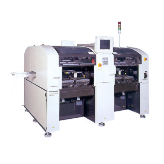
- Page 59 HOW TO SEE DESCRIPTION FOR OPERATION NOTICE This manual is created for CM201-D, CM201-DU, CM201-DH, CM201-DS, CM202-D, CM202-DU, CM202-DH, CM202-DHU, CM202-DK, CM202-DS. Therefore it mainly uses the illustrations and screens of CM202-DH for description. External view Features CM201-D It has a set of mounting stage. •...
- Page 60 HOW TO SEE DESCRIPTION FOR OPERATION External view Features CM202-DH/DK It has two sets of mounting stage. • It mounts two boards at the same time. • Up to 104 feeders can be set. 4U4C-AA00 4U4C-AB01 Front view Rear view CM202-DS 444C-102E E24C-AA00...
- Page 61 HOW TO SEE DESCRIPTION FOR OPERATION Maintenance position This manual is for CM201 and CM202 in common. The operating procedure is mainly described for CM202 AF. Basically, carry out the same maintenance as CM202 AF for CM202 BF, AR, and BR and CM201 AF and AR. Screen display Machine display Flow direction...
- Page 62 = MEMO = 444C-E-XXA00-A05-00 Page 50...
- Page 63 Chapter REGULAR MAINTENANCE Regular maintenance This chapter describes the regular maintenance of this machine. The characteristics of the regular maintenance of this machine are that you can carry out the maintenance based on the run time. It enables the machine to run in a more stable condition. This chapter is constructed as follows.
-
Page 64: Outline Of Maintenance
Outline of Maintenance This machine automatically estimates the time for the regular maintenance by the period time set in advance and the run time, and informs it to the user. Enter the maintenance end after it to save the operation date in the history. You can use the information to estimate the next maintenance period. - Page 65 Outline of Maintenance Select the button which corresponds to the blinking item at the “Main Menu” screen. ∗ For “Regular Maintenance by KME,” select “Routine Maintenance.” Using the arrows on the right side of the touch panel, move the cursor to the line item which is blinking and press Manual .
- Page 66 Outline of Maintenance Press Finish . • The message for checking appear. 444C-EEn-MpMmRm-002 Press Yes . • “Run Time” is reset, and the run time item to the next period is calculated. • “History” is renewed. 444C-EEn-MpMmRm-002 ∗ Past maintenance history can be checked. Press History .
-
Page 67: Maintenance Motions
Outline of Maintenance 1-1-2 Maintenance Motions This machine has “Maintenance Motions” in the program of the machine. Using this mode makes such maintenance as cleaning or lubricating easier and more effective. Entering the maintenance motions Press Maintenance motions . 444C-EEn-MpMm-001 START UNLOCK →... -
Page 68: Regular Check Items For Period
Outline of Maintenance 1-1-3 Regular Check Items for Period This section divides check items and consumable parts requiring exchange for period, and de- scribes them in a list. For detailed procedures, turn to the section under specified “Reference.” ∗ When either the operation hours or the period of time is exceeded, perform the checks. 1. - Page 69 Outline of Maintenance 3. Regular check items every 560 hours (once a month) — — 444C-403TE 4. Regular check items every 3000 hours (once a six months) — — 444C-404TE 5. Regular check items every 6000 hours (once a year) —...
-
Page 70: Regular Check Items For Each Unit
Outline of Maintenance 1-1-4 Regular Check Items for Each Unit Regular check items are divided for unit name. Make use of it for reference. List of regular check items for unit n i l ) t i t l i ) t i ) t i ) t i... - Page 71 Outline of Maintenance Regular check items are divided for the unit and illustrated. Make use of it for reference. = Check = Clean = Apply grease or lubricate (or exchange) = Exchange 2. NG parts discharge box 1. MR unit 1) Pressure gauge 2) Water receiver 1) Tray Cl...
- Page 72 Outline of Maintenance 7. Color touch panel 6. Transfer head 1) Touch panel face 2) Air pass 1) Nozzle shaft support bearing ∗ ∗ ∗ ∗ ∗ This illustration shows the one for CM202-DH. ∗ ∗ ∗ ∗ ∗ This illustration shows the one for CM202-DH. 4U4C-AA00 010DC0AA 8.
-
Page 73: Nozzle Changer
Outline of Maintenance 11. Used tape box (option) 10. Line camera 1) Inside 1) Cover glass 100NC0AA 444C-403P 13. Unit for double tape feeder (option) 12. Cutting unit (option) CM201-D/DU and CM202-D/DU are options. 2) Fixed blade 1) Left-side slide block 1) Linear bearing 2) Movable blade... -
Page 74: Machine Information
Outline of Maintenance 1-1-5 Machine Information You can check each type of information related to the machine at the “Machine Information” screen. Press Machine information at the “Machine maintenance menu” screen. Machine information Machine information The machine name, machine serial number, and the setup date are displayed. -
Page 75: Component Unit Update (Update Of Each Board System)
Outline of Maintenance Version history The updated history of the machine system and recognition system is displayed. The machine system or recognition system is displayed at the line item, and the date when it is updated and that version No. appears in descendent order. 1-1-6 Component Unit Update (Update of Each Board System) Press Compo unit update at the “Ma-... -
Page 76: Action Check
Outline of Maintenance Press Yes . • The update is started. • The message “Update complete“ is displayed when the update finishes successfully. ∗ The message “Restart the system“ is displayed when the installation is complete successfully. Turn on the power of the machine again. 1-1-7 Action Check The feeder sending can be checked. -
Page 77: Lubricating
Lubricating This section describes how to set the cartridge of the grease gun included with the machine as an option, how to supply grease, and the precautions for a lubricating. The structure of a grease gun The grease gun consists of following 4 parts. Make sure of firm setting of the nozzle to the main body, before use. -
Page 78: Loading And Using The Grease Gun
Lubricating 1-2-1 Loading and Using the Grease Gun Loading the grease gun Remove the cap from the cartridge, and screw it into the grease gun. ∗ The looseness may cause leak of the grease. 433C-038P Pull out the chain and lock it to the groove of the oil cylinder. - Page 79 Lubricating Using the grease gun Insert the nozzle tip into the grease nipple. Pump the lever several times. ∗ Make sure of full opening and closing of the lever completely. Insufficient movement of the lever does not pump the grease in the car- tridge.
-
Page 80: Greasing Point
Lubricating 1-2-2 Greasing Point NOTICE Use proper quantity of grease for each greasing point. Extra oil will spread and stick to the camera. Be careful not to contaminate the belt with grease. Remaining grease will deterio- rate the belt early. Main parts requiring lubrication Linear bearing Ball screw... -
Page 81: Setting And Removing The Feeder Base Cover (Only For Du/Dhu Specifications)
Lubricating 1-2-3 Setting and Removing the Feeder Base Cover (Only for DU/DHU Specifications) As for DU/DHU specifications, some operations cannot be performed unless the cover is not removed, depending upon the maintenance item. Remove the cover if necessary. ∗ Make sure of turning off the servo switch, and open the safety cover before these operations. ∗... -
Page 82: Check Every 24 Hours (Routine)
Check Every 24 Hours (Routine) 1-3-1 Checking the MR Unit (before Operation) Tools Philips driver Required time 1 minute Check the air pressure of MR unit and clean the water receiver. ∗ The MR unit is put at lower right of the machine rear side. This operation is for AR only. Open the cover at lower right of the machine rear side. -
Page 83: Cleaning The Cover Glass For The Line Camera (Before Operation)
Check Every 24 Hours (Routine) 1-3-2 Cleaning the Cover Glass for the Line Camera (before Operation) Tools Cloth Required time 1 minute NOTICE This maintenance is current-carrying operation. When you open the safety cover, the power of XY motor is cut. So be sure to open the safety cover to operate. Clean the cover glass for the line camera. -
Page 84: Cleaning The Ng Chip Discharge Box (After Operation)
Check Every 24 Hours (Routine) 1-3-4 Cleaning the NG Chip Discharge Box (after Operation) Tools Required time 1 minute After the production, clean the NG chip discharge box. Turn OFF the power. Open the safety cover. Empty chips in the NG chip discharge box. - Page 85 Check Every 24 Hours (Routine) Draw out the used tape box. CM201-DH, CM202-DH/DHU/DK Used tape box Cast off the used tape in the used tape box. 4H4C-503P CM201-DS, CM202-DS Used tape box E24C-402P 2. The cutting unit is not set Cut off the tape coming out of the outlet of the used tape duct.
-
Page 86: Check Every 140 Hours (Once A Week)
Check Every 140 Hours (Once a Week) 1-4-1 Cleaning the Color Touch Panel Tools Cloth Required time 1 minute Clean the color touch panel. Dirt on it may cause the fault operation. Turn OFF the power. Clean the color touch panel with a cloth. -
Page 87: Cleaning And Lubricating The Tape Feeder Table
Check Every 140 Hours (Once a Week) 1-4-2 Cleaning and Lubricating the Tape Feeder Table Tools Cloth Required time 5 minutes Clean and lubricate the tape feeder table. ∗ For DU/DHU specifications, it is necessary to remove the feeder base cover for the maintenance. “1-2-3 Setting and Removing the Feeder Base Cover (Only for DU/DHU Specifications)”... - Page 88 Check Every 140 Hours (Once a Week) Apply grease to the linear bearing beside the tube feeder table. ∗ Apply grease to the rail which shows the front side. Linear bearing 444C-509P Close the safety cover. SERVO OFF ( ) ON ( Turn ON the servo switch.
- Page 89 Check Every 140 Hours (Once a Week) SERVO Turn OFF the servo switch. ) ON ( OFF ( Open the safety cover. Apply grease to the linear bearing beside the tape feeder table. ∗ Apply grease to the inner side of the rail. Linear bearing 444C-460P Close the safety cover.
-
Page 90: Cleaning And Lubricating The Nozzle
Check Every 140 Hours (Once a Week) 1-4-3 Cleaning and Lubricating the Nozzle Tools Required time 30 minutes Cloth, air ejector, grease gun, syringe and tweezers This part describes changing the nozzle holder set on the transfer head, the nozzles and the vacuum filter, and also describes cleaning and lubricating the optional nozzle changer and the nozzles set on it. - Page 91 Check Every 140 Hours (Once a Week) Rolls of parts Nozzle Nozzle taper face This is the part to be chucked by the nozzle holder of the transfer head. The taper face or chucking groove with dust or dirt will cause air leakage or false chucking.
- Page 92 Check Every 140 Hours (Once a Week) Nozzle changer (option) This unit stocks the nozzle. You can set each nozzle corresponding to the production. The transfer head exchanges the nozzle by chucking it from this unit for the device exchange, and it saves the operation time.
- Page 93 Check Every 140 Hours (Once a Week) UNLOCK Press + Chip Eject pos . • The transfer head moves to the nozzle ex- change position. Transfer head 444C-401P ∗ ∗ ∗ ∗ ∗ When the nozzle changer (option) installed UNLOCK Nozzle changer Press Open...
- Page 94 Check Every 140 Hours (Once a Week) Remove the nozzle holder from the transfer head. Hold the nozzle a little and push it upward. Keeping it pushed up, turn it to the right. Pull it out slowly downward. ∗ For pulling the nozzle holder, be careful not to take off the spring for nozzle cushion.
- Page 95 Check Every 140 Hours (Once a Week) Removing the vacuum filter Insert the pulling jig from the oppo- Filter site side, and remove the dirty filter. (Push it firmly.) Pulling jig 444C-457E Cleaning a. Cleaning the nozzle holder and the nozzle-holder shaft Clean the inside of the nozzle holder with the air ejector and wipe the in- side of the nozzle holder with the...
- Page 96 Check Every 140 Hours (Once a Week) Clean dirt on the outer circumference of the nozzle holder with a cloth. 444C-426P Clean dirt on the spring for nozzle cushion with a cloth. 444C-471P . Soak a swab in alcohol, insert it into the nozzle holder, and turn it in θ...
- Page 97 Check Every 140 Hours (Once a Week) b. Cleaning the nozzle Remove dust in the air pass of the nozzle with the air ejector. Air ejector ∗ Blow the air to the nozzle tip. At this time, be careful not to touch the nozzle tip with an air ejector.
- Page 98 Check Every 140 Hours (Once a Week) ∗ When the nozzle changer (option) is installed, clean it. Shutter Clean the top face of the nozzle changer with a cloth which is soaked with absolute alcohol. ∗ Be careful not to contaminate the contact faces of it and the nozzle reflector.
- Page 99 Check Every 140 Hours (Once a Week) Cleaning the holder of the transfer head Clean the fixing groove (which is reverse L-shaped) on the transfer head with a swab. Wipe the circumference of the tip of the guide shaft section on the nozzle holder with a cloth.
- Page 100 Check Every 140 Hours (Once a Week) b. Checking the nozzle arrangement Check the position to set the nozzle holder. The screen to be displayed and the procedures depend upon the nozzle changer (option). Press Nozzle arrangement at the “Maintenance Motions” screen. •...
- Page 101 Check Every 140 Hours (Once a Week) c. Setting the nozzle holder to the transfer head Fit the positioning projection of the nozzle holder to the positioning groove of the transfer head, for setting it. Transfer head Nozzle holder positioning groove positioning projection 444C-462P 444C-461P...
- Page 102 Check Every 140 Hours (Once a Week) Put away the container put under the transfer head. 444C-419P Close the safety cover. SERVO ) ON ( OFF ( Turn ON the servo switch. ∗ ∗ ∗ ∗ ∗ The nozzle changer is not installed ; proceed to “7. Rechecking the nozzle arrangement.” ∗...
- Page 103 Check Every 140 Hours (Once a Week) Rechecking the nozzle arrangement Ensure that the set nozzle is properly arranged. The nozzle arrangement on the transfer head can be verified by the machine by using the line camera. UNLOCK Press + Nozl set chk . •...
-
Page 104: Cleaning The Support Pin Batch Exchange Table
Check Every 140 Hours (Once a Week) 1-4-4 Cleaning the Support Pin Batch Exchange Table Required time 5 minutes Cleaning brush Tools NOTICE This maintenance is current-carrying operation. When you open the safety cover, the power of XY motor is cut. So be sure to open the safety cover to operate. Clean the support pin batch exchange table. - Page 105 Check Every 140 Hours (Once a Week) Pull out the support pin batch ex- change table. ∗ Pull it slowly by both hands. ∗ Be careful not to fall the foreign body in the LED light (line camera) nor hit it. .
-
Page 106: Checking And Lubricating The Board Conveyor
Check Every 140 Hours (Once a Week) 1-4-5 Checking and Lubricating the Board Conveyor Tools Push-pull gauge and broom Required time 10 minutes NOTICE This maintenance is current-carrying operation. When you open the safety cover, the power of XY motor is cut. So be sure to open the safety cover to operate. Ensure that no trouble on the board transfer belt and roller on the board conveyor. - Page 107 Check Every 140 Hours (Once a Week) Checking the belt tension Measuring position Measure it at the middle of the span. 0306C0AA 0305C0AA Measuring method Measure deflection (δ) of the belt by pressing it at the specified tension (F) with a push-pull gauge.
- Page 108 Check Every 140 Hours (Once a Week) Cleaning and lubricating the board conveyor Clean the surroundings of the board holder and the support pin receiver and directly apply the grease to the width adjustment ball screw and width adjustment linear shaft on the board conveyor. SERVO Ensure that the safety cover is ) ON (...
- Page 109 Check Every 140 Hours (Once a Week) Close the safety cover. SERVO OFF ( ) ON ( Turn ON the servo switch. UNLOCK Pin change Press Down • The board holder moves down to the origin. UNLOCK Press + Conveyor Mid posi . •...
- Page 110 Check Every 140 Hours (Once a Week) Close the safety cover. SERVO OFF ( ) ON ( Turn ON the servo switch. Press Width adjust . UNLOCK Press + continuous moving . • The movable side rail of the board conveyor goes back and forth on the width adjustment axis at full stroke, and spreads the grease over whole area of the width adjustment ball screw...
- Page 111 Check Every 140 Hours (Once a Week) Close the safety cover. SERVO OFF ( ) ON ( Turn ON the servo switch. UNLOCK Pin change Press Down • The board holder moves down to the origin. 444C-E-MMA01-A06-03 Page 1-49...
-
Page 112: Lubricating The X-Y Unit And Z Unit
Check Every 140 Hours (Once a Week) 1-4-6 Lubricating the X-Y Unit and Z Unit Tools Cloth and grease gun Required time 15 minutes NOTICE This maintenance is current-carrying operation. When you open the safety cover, the power of XY motor is cut. So be sure to open the safety cover to operate. Lubricate the linear bearing and ball screw of the X-Y unit and Z unit. - Page 113 Check Every 140 Hours (Once a Week) Lubricate the Z-axis ball screw Grease nipple through the grease nipple. [Grease : SHELL STAMINA GREASE RL2] ∗ Be careful not to infuse too much grease. Otherwise, grease can drop on a board or a motor-overload error during wintertime can occur.
- Page 114 Check Every 140 Hours (Once a Week) Lubricate the Y-axis linear bearing and Y-axis ball screw on the front side through the grease nipple. [Grease : Stamina Grease RL2] Grease nipple for linear bearing 444C-418E 4H4C-511P Grease nipple for ball screw Grease nipple for linear bearing 4H4C-512P...
- Page 115 Check Every 140 Hours (Once a Week) SERVO Close the safety cover. OFF ( ) ON ( Turn ON the servo switch. Press Z axis . UNLOCK Press + Continuous moving . • The Z-axis ball screw of the head repeats to go back and forth at full stroke, and spreads the grease over whole area of it.
- Page 116 Check Every 140 Hours (Once a Week) Procedure for CM201-DH/DS, CM202-DH/DHU/DK/DS Select the operation table. UNLOCK Press + Grease up posi . • Each axis moves to the grease application position. Transfer head 444C-418E Ensure that there is nothing put under the head and press Yes .
- Page 117 Check Every 140 Hours (Once a Week) Lubricate the Z-axis ball screw Grease nipple through the grease nipple. [Grease : SHELL STAMINA GREASE RL2] 444C-523P 444C-418E UNLOCK Press + Run . 444C-EEn-MpMmMm-015 Lubricate the Y-axis linear bearing Grease nipple for and Y-axis ball screw on the rear side linear bearing through the grease nipple.
- Page 118 Check Every 140 Hours (Once a Week) Lubricate the Y-axis linear bearing and Y-axis ball screw on the front side through the grease nipple. [Grease : Stamina Grease RL2] Grease nipple for linear bearing 4H4C-509P 444C-418E 4H4C-510P Grease nipple for Grease nipple for ball screw linear bearing...
- Page 119 Check Every 140 Hours (Once a Week) Lubricate the X-axis linear bearing and X-axis ball screw on the front and rear sides through the grease nipple. [Grease : SHELL STAMINA GREASE RL2] CM201-DH, CM202-DH/DHU/DK X-axis ball screw 444C-418E 4H4C-511P Linear bearing CM201-DS, CM202-DS Linear bearing 444C-418E...
- Page 120 Check Every 140 Hours (Once a Week) SERVO Close the safety cover. OFF ( ) ON ( Turn ON the servo switch. Press Z axis . UNLOCK Press + Continuous moving . • The Z-axis ball screw of the head repeats to go back and forth at full stroke, and spreads the grease over whole area of it.
-
Page 121: Cleaning The Line Camera Lens
Check Every 140 Hours (Once a Week) 1-4-7 Cleaning the Line Camera Lens Tools Blower brush Required time 5 minutes If such as chips and dust adhere to the lens of the line camera, a nozzle looks as if it tapered or a recognition error of chip components can occur. -
Page 122: Cleaning The Forced-Chip-Ejecting Unit
Check Every 140 Hours (Once a Week) 1-4-8 Cleaning the Forced-Chip-Ejecting Unit Tools Required time 5 minutes ∗ The forced-chip-ejecting unit is standard equipment for DS, but an option for DH. . Turn OFF the power supply. . Disengage a catch, open a cover, and remove a brush. -
Page 123: Check Every 560 Hours (Once A Month)
Check Every 560 Hours (Once a Month) 1-5-1 Cleaning the Lubricating the Transfer Head Tools Philips driver, cotton bud, syringe, and vacuum gauge Required time 30 minutes Clean and lubricate the nozzle shaft support bearing and check the vacuum pressure at the nozzle tip. - Page 124 Check Every 560 Hours (Once a Month) Discharge the air. Valve Close the main air valve. Pull up the regulator knob, and turn it to the left until it stops. Make sure the exhaust sound disappears and the gauge shows 0 MPa. Lock the valve lever.
- Page 125 Check Every 560 Hours (Once a Month) Apply a bit of grease to the bearing and groove using a syringe. [Grease : BARRIERTA IEL/V] Push the nozzle holder upward. ∗ Carry out cleaning and lubricating in steps 8 to 11 for all nozzles. 444C-445P Checking the vacuum pressure Ensure that the vacuum pressure is within the specified value.
- Page 126 Check Every 560 Hours (Once a Month) Press in the “Main menu” Machine adjust screen. • The “Machine Adjustment” screen appears. Press Output check . • The “Output Check” screen appears. 444C-EEn-Ma-001 Select the operation table (the one with the transfer head of which the vacuum pressure is measured.) UNLOCK Vacuum pump...
- Page 127 Check Every 560 Hours (Once a Month) Select the nozzle position to be measured, and measure. (Here we start with position 1 as an example.) Turn OFF the vacuum for the nozzle position that will not be measured and pos1 to pos6 of the facing head. UNLOCK Vacuum ∗...
- Page 128 Check Every 560 Hours (Once a Month) Raise the nozzle which has been measured. UNLOCK Nzl Extend ∗ Press for pos 1. Turn OFF the vacuum for the nozzle position which has been measured. UNLOCK Vacuum ∗ Press for pos 1. Measure the nozzle at other position.
- Page 129 Check Every 560 Hours (Once a Month) 1-5-2 Cleaning and Lubricating the Cutting Unit For D/DU, the cutting unit is an option. The cutter consists of the fixed blade and movable blade. ∗ For DU/DHU specifications, it is necessary to remove the feeder base cover for the maintenance. “1-2-3 Setting and Removing the Feeder Base Cover (Only for DU/DHU Specifications)”...
-
Page 130: Cleaning And Lubricating The Cutting Unit
Check Every 560 Hours (Once a Month) 1-5-2 Cleaning and Lubricating the Cutting Unit For D/DU, the cutting unit is an option. The cutter consists of the fixed blade and movable blade. ∗ For DU/DHU specifications, it is necessary to remove the feeder base cover for the maintenance. “1-2-3 Setting and Removing the Feeder Base Cover (Only for DU/DHU Specifications)”... - Page 131 Check Every 560 Hours (Once a Month) Valve Discharge the air. Close the main air valve. Pull up the regulator knob, and turn it to the left until it stops. Make sure the exhaust sound disappears and the gauge shows 0 MPa. Lock the valve lever.
- Page 132 Check Every 560 Hours (Once a Month) Apply the grease to the fulcrum part of the movable blades. Fulcrum part [Grease : SHELL STAMINA GREASE RL2] Fixed blade ∗ Ensure that the blade is not broken. Fulcrum part Movable blade 444C-426E 444C-467P Set the tape chute.
- Page 133 Check Every 560 Hours (Once a Month) Procedure of CM201-DS and CM202-DS Turn OFF the power. Remove the cutting cover. Cutting cover E24C-402P Lubricate through the grease nipples for the cutting unit. [Grease : SHELL STAMINA GREASE RL2] Left (Two locations) Right (One location) E24C-403P E24C-405P...
-
Page 134: How To Check The Setting Of The Blow Pressure
Check Every 560 Hours (Once a Month) 1-5-3 How to Check the Setting of the Blow Pressure Tools Required time 5 minutes Press Machine adjust • The “Machine adjustment menu” screen appears. Press Output check . • The “Output check” screen appears. Select the operation position (the table with the transfer head of which the vacuum pressure is to be mea-... - Page 135 Check Every 560 Hours (Once a Month) UNLOCK Air blow Press • The display turns to be ON, and the air flows into the pass. ∗ Ensure that the air is jetting from the tip of the nozzle. Release the lock of the A valve and adjust the indicating pointer of the B regulator graduation to within the indicating range.
-
Page 136: Check Every 3000 Hours (Once Six Months)
Check Every 3000 Hours (Once Six Months) 1-6-1 Exchanging the Board Transfer Belt and Roller Tools Allen wrench and push-pull gauge Required time 15 minutes The board transfer belt and board transfer roller on the board conveyor must be exchanged regu- larly. - Page 137 Check Every 3000 Hours (Once Six Months) Exchanging the board transfer roller. Hold the nut on the rear side and exchange the board transfer roller of the board conveyor. Remove the board transfer roller using a hexagon wrench. Set the new board transfer roller. 3Y3C-082P ∗...
-
Page 138: Check Every 6000 Hours (Once A Year)
Check Every 6000 Hours (Once a Year) 1-7-1 Exchanging the Cutter Blade Tools Philips driver and allen wrench Required time 30 minutes The fixed and the movable blade mounted in the cutting unit need to be replaced as consumable parts if they are worn because of the cutting of dropped chips. (For D/DU, the cutting unit is an option.) ∗... - Page 139 Check Every 6000 Hours (Once a Year) Press Address . 444C-EEn-MaOc-015 Display “63. AstFront tape cutter Open”, and turn it ON. ∗ If the cover of the cutter parts is not closed, it is impossible to operate. (No.64 should be OFF) Release the air pressure inside the machine.
- Page 140 Check Every 6000 Hours (Once a Year) Turn OFF the power. ∗ Lock the main switch. A worker should carry the key. (DU/DHU only) 444C-457E Remove the 4 fixing bolts, and re- move the chute. Remove the cover positioning bolt of 444C-512P Chute the fixed blade, and set the bolt for...
- Page 141 Check Every 6000 Hours (Once a Year) Remove the fixed blade holding the bolt for lifting. 4H4C-518P Remove the bolt for lifting from the fixed blade, set it to the movable blade. (See the picture on the left) Remove the fixing bolt by using the exclusive tool.
- Page 142 Check Every 6000 Hours (Once a Year) Press the movable blade against the spring pin on the front side. ∗ At this time, take care not to touch the blade parts. Tighten the fixing bolt by using the exclusive tool. Remove the bolt for lifting.
- Page 143 Check Every 6000 Hours (Once a Year) Return the chute to the original posi- tion. • Adjust the position so that the positioning bolt will fit to the 2 positioning holes of the chute (See the picture). Set the 3 fixing bolt, tighten it. Open the air valve.
-
Page 144: Replacing The Vacuum Pump
Check Every 6000 Hours (Once a Year) 1-7-2 Replacing the Vacuum Pump Tools Philips driver, allen wrench Required time 60 minutes The fall of the vacuum pressure will cause the miss of the chip pick-up. For the stability of the vacuum pressure, the replacement of the vacuum pump is required regularly. - Page 145 Check Every 6000 Hours (Once a Year) Notice Before opening the distributor, ensure that the power of the machine is certainly OFF. Remove the 3 wiring connected to the distribution part. Write down the wiring order not to mistake. The mistaken order will cause the reverse of the vacuum pump.
-
Page 146: Replacing The Indicator
Check Every 6000 Hours (Once a Year) 1-7-3 Replacing the Indicator Tools Philips driver Required time 15 minutes If the bulb of the indicator burns out, you will misunderstand the indiction, eventually proper produc- tion is hinderd. And regular replacement is required for the immediate response when the trouble occurs. -
Page 147: Transfer Head : Replacing The Air Cylinder (Replacing Kit)
Check Every 6000 Hours (Once a Year) 1-7-4 Transfer Head : Replacing the Air Cylinder (Replacing Kit) The air cylinder that raises and lowers the nozzle is the most important parts on picking up and mounting. The replacement of the air cylinder means the replacement of the kit, and replace the 6 cylinders at the same time. -
Page 148: Check Every 12000 Hours (Once Two Years)
Check Every 12000 Hours (Once Two Years) 1-8-1 Transfer Head : Replacing the valve (For the Vacuum Change) Tools Philips driver Required time 120 minutes The valve for the vacuum change is an important parts that control the vacuum change while picking and mounting. - Page 149 Check Every 12000 Hours (Once Two Years) Wipe out the flange dirt on the pack- ing or setting part at the lower part of the valve with a soft cloth soaked with alcohol. 444C-497P Align the packing with the bolt hole of the new valve, and set it to the flange.
-
Page 150: Xy Unit : Replacing (Replacing Kit) The Valve (For Selecting The Nozzle, For The Cylinder)
Check Every 12000 Hours (Once Two Years) 1-8-2 XY Unit : Replacing (Replacing Kit) the Valve (For Select ing the Nozzle, For the Cylinder) Tools Philips driver, allen wrench Required time 30 minutes The bad motion owing to the abrasion of the valve leads to the bad motion of the cylinder, and occurs the miss of the picking and mounting. - Page 151 Check Every 12000 Hours (Once Two Years) Remove the wiring connected to the valve. ∗ Write down the setting position and wiring name. The setting working will be smooth. 444C-500P Remove the pipe (tube) connected to the valve (manifold). ∗ Write down the setting position and order. The setting work will be smooth.
- Page 152 Check Every 12000 Hours (Once Two Years) Connect the pipe and wiring as be recorded. Set the head cover. Turn ON the power. Press Machine adjust • The “Machine adjustment menu” screen appears. Press Return to origin . • Returning to origin is performed. To the next page 444C-E-MMA01-A09-05 Page 1-90...
- Page 153 Check Every 560 Hours (Once a Month) UNLOCK START Press Press Output check . • “Output check” screen is displayed. Select the operation position (the table with the transfer head of which the vacuum pressure is to be mea- sured). To the next page 444C-E-MMA01-A09-04 Page 1-91...
-
Page 154: Tape Feeder Base : Replacing The Valve (For Cylinder Of The Tape Feeder)
Check Every 12000 Hours (Once Two Years) Ensure that the arrangement of the nozzles is the same as the nozzle positions of the head arrangement, starting form the position1. UNLOCK Nzl Extend ∗ Press in order from pos 1, and check the nozzle come out. 1-8-3 Tape Feeder Base : Replacing the Valve (For Cylinder of the Tape Feeder) If bad motion owing to the abrasion of the valve, the motion of the tape feeder will not be accurate,... -
Page 155: Check Every 18000 Hours (Once Three Years)
Check Every 18000 Hours (Once Three Years) 1-9-1 Transfer Head : Replacing the Shaft Abrasion of the shaft will cause an unsmooth nozzle motion. That will be the major factor of pick-up/ mount trouble. So the parts need to be replaced regularly. ∗... -
Page 156: Replacing Consumable Parts
1-10 Replacing Consumable Parts 1-10-1 Replacing Color Touch Panel Back Light Back Light Built-in Color Touch Panel Position The color touch panel of this machine has a back light built-in. Back light Color touch panel Screw Cover 444C-463E WARNING CUT OFF THE POWER SUPPLY BEFORE CARRYING OUT ANY WORK FOR THE MACHINE. - Page 157 Replacing Consumable Parts . Remove one M3 countersunk screw, and remove the hatch (plate) for back light replacement. One M3 countersunk screw Hatch (Plate) for back light replacement 493C-024P . Raise the bending 1 with a needle- nose plier and the like, and pull out the power supply connector.
- Page 158 = MEMO = 444C-E-MMA01-A09-00 Page 1-96...