Panasonic PAW-160MAH2L Installation Instructions Manual
Air handling unit kit
Hide thumbs
Also See for PAW-160MAH2L:
- Installation instructions manual (102 pages) ,
- Installation instructions manual (31 pages) ,
- Installation instructions manual (114 pages)

Related Manuals for Panasonic PAW-160MAH2L


Summary of Contents for Panasonic PAW-160MAH2L
- Page 1 Air Handling Unit Kit Installation Instructions PAW-160MAH2(L/M) PAW-280PAH2(L/M) PAW-280MAH2(L/M) PAW-560MAH2(L/M) PAW-280PAH3M AHU Kit – Installation Instructions – 2021...
- Page 2 Notes:...
- Page 3 The copyright of this Manual remains with the manufacturer. No part of this Manual may be reproduced or processed using electronic systems, or distributed in any form without the written consent of Panasonic Marketing Europe GmbH. Infringements which conflict with the above-mentioned information will render you liable for damages.
-
Page 4: Table Of Contents
Table of Contents General information and safety notes General information Safety notes Instructions for the safe handling of R32 1.3.1 Calculating the density limit 1.3.2 Preventing leakages 1.3.3 Detecting leaks 1.3.4 Repairing leaks Warranty policy Ventilation theory and air handling units Purpose of air-conditioning Mechanical ventilation systems Air handling units... - Page 5 Wiring layout Wiring system diagrams Connection of external signal lines Test Run Control Remote controller Thermostat 7.2.1 Control and display elements 7.2.2 Operation 7.2.3 Initial Settings 7.2.4 Error Codes 7.2.5 Maintenance and Service AHU Kit – Installation Instructions – 09/2021...
-
Page 6: General Information And Safety Notes
This document contains the installation instructions for the Panasonic AHU Kits. Intended use The intended use of AHU Kits is to connect Panasonic ECOi, ECO G, PACi and PACi NX outdoor units to third-party air handling unit systems, using the same refrigerant circuit as the outdoor unit. - Page 7 General information and safety notes Important: Validity of this document Due to the ongoing development and innovation of Panasonic products, this document and all the information contained herein may not reflect the current status of the relevant products. Preliminary or missing information will be updated and added on an ongoing basis and published at the discretion of Panasonic.
-
Page 8: Safety Notes
General information and safety notes Safety notes To avoid possible harm to persons or damage to products, read and follow these safety notes. WARNING The following precautions need to be followed strictly, in order to avoid hazardous situations, which could result in death or serious injury. Electric shock or fire may result from inadequate or incorrect installation or wiring procedures. -
Page 9: Instructions For The Safe Handling Of R32
General information and safety notes Incorrect installation can result in falling equipment causing damage, injuries or other accidents. ► Install in a location that is fully strong enough to support the weight of the equipment. ► Perform installation that is secure enough to withstand earthquakes, tornadoes, storms and other strong winds. -
Page 10: Calculating The Density Limit
General information and safety notes WARNING The following precautions need to be followed strictly, in order to avoid hazardous situations, which could result in death or serious injury. A fire or explosion hazard and the generation of poisonous gas may result if R32 refrigerant gas comes into contact with open flames. - Page 11 General information and safety notes While there are no floor area limitations for refrigerant charges of less than 1.23 kg, the minimum floor area [A ] for larger refrigerant charge amounts can be calculated by the following formula: ceiling-mounted 2.5 x LFL = minimum floor area (m refrigerant charge (kg) wall-mounted...
- Page 12 General information and safety notes Density limit diagrams The following diagrams roughly demonstrate the relation between the amount of refrigerant charged for the relevant R32 PACi or PACi NX outdoor units ([mc]) and the required minimum installation space floor area. AHU units For the AHU units, the density limit diagram shows three different “Density Limit Lines”, where each line applies to a different AHU unit installation height and installation orientation (horizontal/vertical)
- Page 13 General information and safety notes Line 1 Line 2 Line 3 Line 1 Line 2 Line 3 Line 1 Line 2 Line 3 1.22 12.8 11.7 105.1 21.5 32.1 288.6 14.5 12.4 111.2 22.3 33.2 298.7 16.8 13.1 117.5 23.0 34.4 308.9 19.3...
- Page 14 General information and safety notes U-60PZ2E5, U-71PZ2E5, U-36PZH2E5, U-50PZH2E5, U-60PZH2E5 10.0 * U-36PZH2E5, U-50PZH2E5 Can not be installed Can be installed Cannot be installed ]: refrigerant charge (kg) of the outdoor unit 1.22 1.35 1.80 Standard Elite U-60PZ2E5 U-36PZH2E5 U-60PZH2E5 U-71PZ2E5 U-50PZH2E5 ] (kg)
- Page 15 General information and safety notes U-100PZ2E5, U-100PZ2E8, U-125PZ2E5, U-125PZ2E8, U-140PZ2E5, U-140PZ2E8 20.0 18.0 16.0 * U-100PZ2E5, U-100PZ2E8 14.0 Cannot be installed Can be installed 12.0 10.0 Cannot be installed ]: refrigerant charge (kg) of the outdoor unit 1.22 3.50 3.88 Standard U-100PZ2E5 U-125PZ2E5...
- Page 16 General information and safety notes Installation height of indoor unit (h Indoor unit type Density limit line ≥ 2.2 m AHU unit Line 1 1.8 m ≤ h < 2.2 m AHU unit Line 2 < 1.8 m AHU unit Line 3 U-36PZ3E5, U-50PZ3E5, U-60PZ3E5A, U-71PZ3E5A Refrigerant charge amount (i.e.
- Page 17 General information and safety notes 15.0 140.0 14.0 Line 3 Line 2 13.0 120.0 12.0 100.0 11.0 10.0 80.0 Line 1 60.0 40.0 20.0 2.40 3.70 ]: refrigerant charge (kg) of the outdoor unit 2.40 3.70 ]: refrigerant charge (kg) of the outdoor unit Standard U-100PZ3E5 U-125PZ3E5...
-
Page 18: Preventing Leakages
General information and safety notes U-71PZH3E5, U-71PZH3E8, U-100PZH3E5, U-100PZH3E8, U-125PZH3E5, U-125PZH3E8, U-140PZH3E5, U-140PZH3E8 Installation height of indoor unit (h Indoor unit type Density limit line ≥ 2.2 m AHU unit (horizontal installation) Line 1 1.8 m ≤ h < 2.2 m AHU unit (horizontal installation) Line 2 <... -
Page 19: Detecting Leaks
General information and safety notes 1.3.3 Detecting leaks ● If a leak is suspected, remove or extinguish all naked flames and ventilate the space immediately. ● To search for and detect any refrigerant leaks, never use potential sources of ignition like e.g. -
Page 20: Ventilation Theory And Air Handling Units
Ventilation theory and air handling units Ventilation theory and air handling units Purpose of air-conditioning The purpose of air-conditioning is to provide comfortable indoor air conditions for the room occu- pants and to provide energy saving potentials for the owner. Comfort If room occupants feel “comfortable“... -
Page 21: Mechanical Ventilation Systems
Ventilation theory and air handling units Mechanical ventilation systems Main components of mechanical ventilation systems The main components of a mechanical ventilation system are the following: ● Air handling unit (AHU) ● Air ducts ● Air distribution elements Outside air Exhaust air Return air Supply air... - Page 22 Connecting AHU systems via the AHU Kit to ECOi/ECO G or PACi outdoor units The following graphic shows an example for connecting a third-party air handling unit via the Pana- sonic AHU Kit to Panasonic ECOi/ECO G or PACi outdoor units. AHU Kit – Installation Instructions – 09/2021...
- Page 23 Ventilation theory and air handling units Air handling unit control by external 0–10 V signal External control system Air Handling Unit Kit ºC ºC PACi or ECOi/ECO G outdoor unit Air Handling Unit 1 This schematic layout applies only to the advanced and medium AHU Kit versions (MAH2/PAH2/PAH3) only, because they feature an in-built CZ-CAPBC2 interface handling the 0–10 V control.
-
Page 24: Product Description
Product description General description The Panasonic AHU Kits offer a wealth of connectivity possibilities so that they can be easily inte- grated into many systems. The AHU Kits are part of an on-going development process aiming at constant improvement of the product to better meet customer demand. -
Page 25: Scope Of Supply
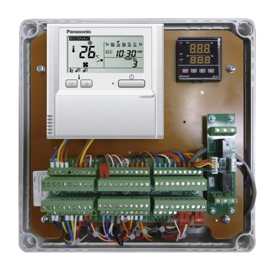
Control unit including transformer Relays Terminal boards Remote controller (CZ-RTC5B) – Remote controller (CZ-RTC6BL) – – – – – – Compatibility with Panasonic H&C Control App – – – – – – Compatibility with Panasonic H&C Diagnosis App – – – –... - Page 26 Product description Medium version: PAW-280PAH2M* Remote controller (CZ-RTC5B) Terminal board with 6 connectors CZ-CAPBC2 interface (on rear side) * Shown as an example and with transparent front cover removed. Layout also applicable for ECOi and ECO G, see table above, → 3.2 Scope 25, for details.
- Page 27 Product description Control functions provided as standard by integral components CZ-RTC5B / CZ-RTC6BL remote controller ● Operation-ON/OFF ● Mode selection ● Temperature setting ● Parameter settings TR-16 / TR-16e Additional Thermostat (advanced version only) ● Target temperature setting based on ambient temperature with proportional integral logic* ●...
- Page 28 Product description PAW-T10 PCB to connect to T10 connector (light and advanced versions only) ● Dry contact PCB for easy control of the unit ● Operation ON/OFF input signal > PAW-T10 terminal I(1); I(2). ● Remote control prohibition > PAW-T10 terminal I(3); I(4). ●...
- Page 29 Product description Mounting boards MAH2/PAH2 Upper mounting board – front side 1 Remote controller (CZ-RTC5B) 2 Thermostat (TR-16 / TR-16e) 3 External signal control PCB (PAW-T10) 4 Terminal board with 6 connectors (labelled Section A to Section F) each with 20 con- tacts MAH2/PAH2 Upper mounting board –...
- Page 30 Product description PAH3 Mounting board 1 Remote controller (CZ-RTC6BL) 2 Main control board (PCB name: ACXA73-38670) 3 Terminal board 4 Fan relay 5 Fan control board (PCB name: ACXA73-39890) 6 CZ-CAPBC2 interface for 0-10 V control (PCB name: ACC-SP1A) 1 Not available in all versions. 2 For details see →...
-
Page 31: System Lineup
Product description System lineup System lineup – ECOi systems Capacity Outdoor unit combination AHU Kit combination U-... PAW-... HP kW all Mini ECOi/ECOi outdoor units 160MAH2(L/M) – – – all Mini ECOi/ECOi 2-pipe and 3-pipe outdoor units with 280MAH2(L/M) – –... - Page 32 Product description System lineup – ECO G systems Capacity Outdoor unit AHU Kit PAW-160MAH2(L/M) all ECO G outdoor units PAW-280MAH2(L/M) all ECO G 2-way outdoor units all ECO G 2-way outdoor units PAW-560MAH2(L/M) 1 PAW-160MAH2(L/M): ● Like any other standard indoor unit, PAW-160MAH2(L/M) can be installed in combination with all ECO G outdoor units.
-
Page 33: System Overview
Product description System lineup – PACi NX systems Capacity Outdoor unit AHU Kit (kW) PACi NX Standard PACi NX Elite Single-phase Three-phase Single-phase Three-phase units units units units U-36PZ3E5 – U-36PZH3E5 – U-50PZ3E5 – U-50PZH3E5 – U-60PZ3E5A – U-60PZH3E5 – U-71PZ3E5A –... - Page 34 Product description System example for ECOi single-connection system ºC ºC PAW-280MAH2 ECOi outdoor unit Piping Air Handling Unit Multi-connection system Note: The following restrictions apply only if PAW-560MAH2(M/L) is used alone or in combination with other AHU Kits. For all other AHU Kits and AHU Kit combinations without PAW-560MAH2(M/L) no such restrictions apply.
- Page 35 Product description System example for ECOi multi-connection system (140 kW capacity) Fan operation signal 28 kW heat ECOi outdoor units exchanger RC group wiring motor control PAW-280MAH2 56 kW heat exchanger PAW-560MAH2 56 kW heat 16 HP 16 HP 18 HP exchanger Air inlet temperature sensor Gas tube...
- Page 36 Product description System Overview – PACi and PACi NX systems Single-connection system only Strainer (liquid pipe & gas pipe) min. Ø 25.4 mm (field supplied) AHU Kit enclosure (complete) Thermistor for liquid pipe (E1) AHU system (field supplied) Thermistor for heat exchanger pipe middle (E2) Remote controller (integrated in AHU Kit enclosure) Thermistor for suction air (TA) Outdoor unit...
-
Page 37: Technical Data
Product description Technical data Technical data – AHU Kit MAH2/PAH2 generation PAH3 generation Power source V / ph / Hz 220 ... 240 / 1 / 50 220 ... 240 / 1 / 50 Rated current consumption Rated power consumption (max.) 18.0 18.0 Dimensions (enclosure) - Page 38 Product description PAH3 generation Right side view Front view Left side view Rear view Top view Important Apart from the technical data and limitations given in the following tables, the technical data and limitations of the relevant outdoor units, local wiring and piping design regulations and approved best practices need to be observed in installation procedures.
- Page 39 Product description Technical data and limitations – ECOi and ECO G systems – R410A (cont.) AHU Kit HP 50¹ 60¹ 70¹ 80¹ AHU Kit model PAW-560MAH2(L/M) + PAW-560MAH2(L/M) + PAW-560MAH2(L/M) + PAW-560MAH2(L/M) + PAW-560MAH2(L/M) + PAW-560MAH2(L/M) + PAW-560MAH2(L/M) + PAW-560MAH2(L/M) + PAW-280MAH2(L/M) PAW-560MAH2(L/M) PAW-560MAH2(L/M) +...
- Page 40 Product description Technical data and limitations – PACi systems – R410A (cont.) AHU Kit PAW-280PAH2(L/M) or PAW-280PAH3M Outdoor unit – PACi Elite U-36PE2E5A U-50PE2E5A U-60PE2E5A U-71PE1E5A U-100PE1E5A U-125PE1E5A U-140PE1E5A Nominal cooling capacity 10.0 12.5 14.0 Nominal heating capacity 11.2 14.0 16.0 Piping connections Liquid pipe...
- Page 41 AND an ambient air temperature limit above which it may not be possible to pump down the complete refrigerant charge (including all additional refrigerant) into the outdoor unit. Note: The AHU DX coil must be designed according to Panasonic specification. Calculation example for total additional refrigerant charge (R410A)
- Page 42 Product description Technical data and limitations – PACi systems – AHU Kit PAW-280PAH2(L/M) or PAW-280PAH3M Outdoor unit – PACi Standard U-60PZ2E5 U-71PZ2E5 U-100PZ2E5 U-125PZ2E5 U-140PZ2E5 U-100PZ2E8 U-125PZ2E8 U-140PZ2E8 Nominal cooling capacity 10.0 12.5 14.0 10.0 12.5 14.0 Nominal heating capacity 10.0 12.5 14.0...
- Page 43 AND an ambient air temperature limit above which it may not be possible to pump down the complete refrigerant charge (including all additional refrigerant) into the outdoor unit. Note: The AHU DX coil must be designed according to Panasonic specification. Calculation example for total additional refrigerant charge (R32)
- Page 44 Product description AHU DX coil additional refrigerant charge: 0.83 kg/dm Refrigerant charge at shipment is sufficient for AHU DX coil volume up to 1,4 dm Total additional refrigerant charge calculation ((1.7 dm – 1.4 dm ) x 0.83 kg/dm ) + (10 m x 0.035 kg/m) = 0.249 kg + 0.35 kg = 0.599 kg Calculation example for number of passes in the heat exchanger The minimum number of passes in the AHU heat exchanger is restricted.
- Page 45 AND an ambient air temperature limit above which it may not be possible to pump down the complete refrigerant charge (including all additional refrigerant) into the outdoor unit. Note: The AHU DX coil must be designed according to Panasonic specification. Calculation example for total additional refrigerant charge (R32)
- Page 46 Product description Pipes additional refrigerant charge: 0.045 kg/m AHU DX coil additional refrigerant charge: 0.83 kg/dm³ Refrigerant charge at shipment is sufficient for AHU DX coil volume up to 1.8 dm³ Total additional refrigerant charge calculation ((2.0 dm³ – 1.8 dm³) x 0.83 kg/dm³) + (10 m x 0.045 kg/m) = 0.166 kg + 0.45 kg = 0.616 kg Calculation example for number of passes in the heat exchanger The minimum number of passes in the AHU heat exchanger is restricted.
-
Page 47: Installation
Installation Installation Installation of AHU Kit WARNING Electric shock from live power supply cords Electric shock may result from contact with live power supply cords. ► Wiring installation must only be performed by a qualified electrician. ► Before starting to work on any machines or devices, always switch off the power supply and lock it in switched-off position. - Page 48 Installation 3. Loosen the 4 screws in the corners of the enclosure and remove the cover from the enclosure. 4. Mount the backside of the enclosure to the wall or surface using field-supplied fixing screws inserted through the previously prepared holes at each corner. ATTENTION Signal errors through noise from live power supply cords Power supply cords can generate noise, which may cause signal errors, if they are run in close...
-
Page 49: Pah3 Generation
Installation Important Please note that the connectors can be unplugged for easy installation. As connectors A and D are intended for connecting the 230 V AC power supply wiring, they have special blind ports, which prevent them from being plugged back into the low-voltage connectors B, C, E or F. 6. - Page 50 Installation 3. Open the front-side door of the enclosure as shown below (left), and mount the backside of the enclosure to the wall or surface using field-supplied fixing screws inserted through the previously prepared holes at each corner as shown below (right). 4.
-
Page 51: Installation Of Refrigerant Piping
Installation 4.1.3 Installation of refrigerant piping When installing the refrigerant piping, the following limitations and restrictions need to be observed: ● Maximum actual and equivalent piping length ● Maximum branch pipe length to AHU Kit ● Maximum branch pipe length difference (between longest and shortest piping from the first branch) ●... - Page 52 Installation When installing the expansion valve, the following limitations and restrictions need to be observed: ● Wires must not be installed externally. Cable protection such as conduit is required. ● Do not detach connector. ● The distance from AHU heat exchanger must not exceed 6 m. ●...
-
Page 53: Installation Of Thermistors
Installation Installation of thermistors ATTENTION Damage to the thermistor wires Exposing the wires of thermistors to the outside and/or to direct sunlight might damage the wires and should therefore be avoided. ► Attach the AHU Kit either directly to the Air Handling Unit or to a wall nearby and make sure that it is not exposed to direct sunlight. -
Page 54: Installation Of Thermistor On Gas Pipe
Installation 4.3.1 Installation of thermistor on gas pipe Installation of thermistor on gas pipe – ECOi and ECO G systems Mount “E3” thermistor to the gas pipe of the AHU heat exchanger according to the following instructions. For PAW-160MAH2(L/M) 1. Attach the gas pipe thermistor onto the collecting gas pipe in the heat exchanger. 2. -
Page 55: Installation Of Thermistor On Liquid Pipe
Installation 4.3.2 Installation of thermistor on liquid pipe Mount “E1” thermistor to the liquid pipe of the AHU heat exchanger according to the following instructions. 1. Attach the liquid pipe thermistor to the liquid pipe located in the lowest position after the distributor in the heat exchanger. -
Page 56: Installation Of Thermistor For Suction And Discharge Air Stream
Installation 2. Cover the thermistor and pipe with aluminum tape (field-supplied). 3. Fix thermistor with two bands. Then, run the wire downwards in a loop, to avoid putting tension to it 4. Cover the aluminum tape with thermal insulation. And also cover the sensor (copper portion) with thermal insulation completely. - Page 57 Installation There are three different methods to achieve this aim. Method A: Cutting JP001 to ignore capacity One possibility is to cut jumper JP001 on the outdoor unit main PCB. Important Method A is only applicable to the following combinations of PACi outdoor units and AHU Kits: ●...
- Page 58 Method B: Changing outdoor unit setting to ignore capacity Another possibility is to change the outdoor unit settings by using a separate standard wired remote controller, CZ-RTC2 or CZ-RTC4, which can be obtained from Panasonic as optional service parts. Important Method B is only applicable to the following combinations of PACi outdoor units and AHU Kits: ●...
- Page 59 Installation Standard – R410A Elite – R410A Outdoor unit maintenance remote CN-RC U-100PEY1E5 U-60PE1E5A controller U-125PEY1E5 U-71PE1E5A U-100PEY1E8 U-100PE1E5A U-125PEY1E8 U-125PE1E5A Optional special service wiring U-140PEY1E8 U-140PE1E5A (CV6242785082 or PAW-MRC) U-71PE1E8A U-100PE1E8A U-125PE1E8A U-140PE1E8A Standard wired remote controller CZ-RTC4 (CV6233317854) Elite –...
- Page 60 Installation Elite – Outdoor unit maintenance remote CN-RC U-71PZH2E8 controller U-100PZH2E8 U-125PZH2E8 U-140PZH2E8 Optional special service wiring (CV6242785082 or PAW-MRC) Standard wired remote controller CZ-RTC4 (CV6233317854) 2. Verify that the display of the maintenance remote controller is working. 3. Simultaneously press the “Spanner” and “Leave Home” buttons for at least 4 seconds. Depending on which model you are using as maintenance remote controller, CZ-RTC2 or CZ- RTC4, the buttons look differently and are located at different positions: CZ-RTC2...
- Page 61 Installation 2. Simultaneously press and hold the relevant three-button combination on the remote controller (see below) for at least 4 seconds, until the “Maintenance func” screen appears on the display. Note: If the system is a combination of a PACi NX outdoor unit (PZ3/PZH3) and a PAH3 AHU Kit model, this step has to be performed within 30 seconds after powering on the system while auto-addressing is in progress and the message “Assigning”...
- Page 62 Installation CZ-RTC5B CZ-RTC6BL — — Detailed settings Detailed settings 20:30 (THU) Unit no. Unit no. Code no. Set data Code no. 000011 0001 Set data 0001 0001 Sel. Next 6. Highlight the “Set data“ option using the “RIGHT” button (RTC5B) or the “DOWN” and “ENTER” buttons (RTC6BL) respectively.
- Page 63 Installation 8. Once the setting procedure is completed, exit the “Detailed settings” mode by pressing the “RETURN” button (RTC5B) or “MENU” button (RTC6BL) respectively. This will invoke a confirmation message (see below). Select “YES” with the “LEFT“ and “RIGHT“ buttons (RTC5B) or “UP”...
-
Page 64: Electrical Wiring
Electrical Wiring Electrical Wiring General precautions on wiring WARNING Electric shock from live power supply cords Electric shock may result from contact with live power supply cords. ► Wiring installation must only be performed by a qualified electrician. ► Before starting to work on any machines or devices, always switch off the power supply and lock it in switched-off position. - Page 65 Electrical Wiring Stranded wire 1. Cut the wire end with cutting pliers, then strip the insulation to expose the stranded wiring about 10 mm and tightly twist the wire ends. Wire-end sleeve 2. Using a flat-blade screwdriver, loosen the terminal screw(s) on the terminal plate. 3.
-
Page 66: Terminal Board Layout
Electrical Wiring Terminal board layout 5.3.1 MAH2/PAH2 models Terminal layout – Main terminal board (CR-UXRP71B-P) = Input or Output necessary to connect. = Input or Output can be connected if required. Section A Connections Name In / Out Allocation Function Description Alarm Signal External Potential:... - Page 67 Electrical Wiring Section C Connections Name In / Out Allocation Function Comment Recirculat. Operation Heating Operation Cooling Operation Status Outputs Internal Potential: 12 V DC Thermostat ON Defrost Operation Potential for ON2 to ON6 (12 V DC) Potential for DI1 to DI3 2 types of usage: a) Potential-free: Digital Inputs...
- Page 68 Electrical Wiring Section F Connections Name In / Out Allocation Function Comments M2-6 Advanced & Medium: Activation of Remove bridge for use of demand control (FREE) demand control (if bridge is intact and in place, temperature Advanced & Medium: Activation of setpoint control is active) M2-5 demand control...
- Page 69 Electrical Wiring Terminal layout – CZ-CAPBC2 / ACC-SP1A (for advanced and medium versions only) CZ-CAPBC2 interface, terminal block CN1 Connections Polarity Name Allocation Function Comments By factory default connected 12 V power supply (12V) – By factory default connected By factory default connected (Start) (12V) Remote control line A...
- Page 70 Electrical Wiring CZ-CAPBC2 digital input functionality The CZ-CAPBC2 digital inputs offer the following functionality settings. Switch S1: Control type setting VOLTAGE NON VOLTAGE Control Control 0-140Ω type type 0-10V – – – – – – – ● ● – – –...
-
Page 71: Pah3M Model
Electrical Wiring Switch S3: Digital input configuration setting (voltage/non-voltage signals) Depending on the BMS digital input (DI) configuration, switch S3 on the CZ-CAPBC2 interface can be set for the digital input terminals to accept either non-voltage signals from dry contacts (factory default: “NON VOLTAGE”) or 12 –... - Page 72 Electrical Wiring Allocation Function Description Terminal No. X4.1 No polarity Suction Temperature Sensor TA (included) (Room Temperature Sensor) X4.2 No polarity E1.1 X4.3 No polarity Sensor E1 / TH2 E1.2 X4.4 No polarity E2.1 X4.5 No polarity Sensor E2 / TH3 E2.2 X4.6 No polarity...
- Page 73 Electrical Wiring Allocation Function Description Terminal No. M2.1 X6.1 4 - 20 mA Analog output (Room temperature monitor), Indoor temperature Analogue output terminals monitor output. Output current : 4 to 20 mA. Temperature indica- tion range : 5 to 36 °C, 0.5 °C step M2.2 X6.2 Potential of M2.1...
-
Page 74: Wiring Layout
Electrical Wiring Wiring layout Wiring layout – MAH2 models PAW-160MAH2L for t° t° t° t° AHU Kit – Installation Instructions – 09/2021... - Page 75 Electrical Wiring PAW-160MAH2M for t° t° t° t° AHU Kit – Installation Instructions – 09/2021...
- Page 76 Electrical Wiring PAW-160MAH2 for t° t° t° t° AHU Kit – Installation Instructions – 09/2021...
- Page 77 Electrical Wiring PAW-280MAH2L for t° t° t° t° AHU Kit – Installation Instructions – 09/2021...
- Page 78 Electrical Wiring PAW-280MAH2M for t° t° t° t° AHU Kit – Installation Instructions – 09/2021...
- Page 79 Electrical Wiring PAW-280MAH2 for t° t° t° t° AHU Kit – Installation Instructions – 09/2021...
- Page 80 Electrical Wiring PAW-560MAH2L for t° t° t° t° AHU Kit – Installation Instructions – 09/2021...
- Page 81 Electrical Wiring PAW-560MAH2M for t° t° t° t° AHU Kit – Installation Instructions – 09/2021...
- Page 82 Electrical Wiring PAW-560MAH2 for t° t° t° t° AHU Kit – Installation Instructions – 09/2021...
- Page 83 Electrical Wiring Wiring layout – PAH2 models PAW-280PAH2L for t° t° t° AHU Kit – Installation Instructions – 09/2021...
- Page 84 Electrical Wiring PAW-280PAH2M for t° t° t° AHU Kit – Installation Instructions – 09/2021...
- Page 85 Electrical Wiring PAW-280PAH2 for t° t° t° AHU Kit – Installation Instructions – 09/2021...
- Page 86 Electrical Wiring Wiring layout – PAH3M model PAW-280PAH3M for for M2.6 M2.5 M2.4 M2.3 M2.2 M2.1 E2.2 E2.1 E1.2 E1.1 AHU Kit – Installation Instructions – 09/2021...
-
Page 87: Wiring System Diagrams
Electrical Wiring Wiring system diagrams Important ● The letter coding (A to F) used in this section refers only to the wiring system diagrams in this section. ● For information on “(A) Power supply of outdoor unit” refer to the “Installation Instructions“... - Page 88 Electrical Wiring Wiring system diagram – ECO G systems AHU Kit Power supply 220 – 240V ~50/60Hz Outdoor unit Ground Power supply Remote 220 – 240V ~50/60Hz controller Ground Ground Recommended wire lengths and diameters AHU Kit Type (B) Power supply Time delay fuse or circuit breaker PAW-160/280/560MAH2(M/L) 2.5 mm...
- Page 89 Electrical Wiring Recommended wire lengths and diameters AHU Kit Type (B) Power supply Time delay fuse or circuit breaker PAW-280PAH2(M/L) 2.5 mm (AWG#13) 10 – 16 A Max. 150 m Control wiring (C) Inter-unit control wiring (D) Remote control wiring (E) Control wiring for group (between outdoor unit and AHU Kit) control 1...
- Page 90 Electrical Wiring Recommended wire lengths and diameters AHU Kit Type (B) Power supply Circuit breaker PAW-280PAH3M Min. 0.75 mm Max. 25.0 m Control wiring (C) Inter-unit control wiring (D) Remote control wiring (E) Control wiring for group (between outdoor unit and AHU Kit) control Min.
- Page 91 Electrical Wiring For three-phase outdoor units – Single-system connection AHU Kit Outdoor unit Power supply 380 – 415V ~50/60Hz Ground Remote controller Central control system (optional) For three-phase outdoor units – Multi-system connection AHU Kit Outdoor unit Power supply 380 – 415V ~50/60Hz Ground Remote controller...
- Page 92 Electrical Wiring Recommended wire lengths and diameters AHU Kit Type (F / G) Connection cable between outdoor and AHU Kit (F) Outdoor units: (G) Outdoor units: (G) Outdoor units: U-36~50PZ3E5, U-100~140PZ3E5, U-71~140PZH3E5, U-60~71PZ3E5A, U-100~140PZ3E8 U-71~140PZH3E8 U-36~60PZH3E5 PAW-280PAH3M Min. 1.5 mm² (1) Min.
- Page 93 Electrical Wiring 3. Refrigerant Circuit (R.C.) address should be set on the outdoor unit as follows: – for ECOi and PACi systems before turning the power on – for ECO G and PACi NX systems after turning the power on. 4.
- Page 94 Electrical Wiring > Note that setting 3 or more terminating resistances to “SHORT” (operative) is prohibited. Central controller Outdoor unit Indoor unit Indoor unit Indoor unit Outdoor unit Indoor unit Indoor unit Indoor unit Outdoor unit Indoor unit ● In case that the inter-unit control wiring in the link are mixed with 3-line and 2-line connections: >...
-
Page 95: Connection Of External Signal Lines
Electrical Wiring 10. If branching the inter-unit control wiring, the number of branch points should be 16 or fewer. (Branches that are less than 1m are not included in the total branch number.) Outdoor unit Outdoor unit Outdoor unit Indoor unit Indoor unit Indoor unit Indoor unit... - Page 96 Electrical Wiring Two suitable methods will be explained in the following sections. All wiring diagrams are just exam- ples. It is not necessary to build the electric circuit with 230 V AC. Any other suitable lower voltage being available on site may be used as well. Method A: For standard fan control For systems with standard fan control, the external signal lines can simply be connected to the contacts provided by the AHU Kit.
- Page 97 Electrical Wiring For all models ● The external signal lines must be inserted drooped in the AHU body and protected by a clamp with the drooping wire being close to the AHU Kit to avoid water reaching the AHU Kit. Inside of AHU AHU Kit Blower signal and...
- Page 98 Electrical Wiring Electric circuit example – ECOi systems Multi-connection systems with 3 AHU Kits AHU Kit Field-supplied 10P Connector Blower signal output AHU Kit 10P Connector Blower signal output Blower signal AHU Kit 10P Connector Blower signal output Electric circuit example – PACi systems Single-connection system AHU Kit Field-supplied...
- Page 99 Electrical Wiring As an alternative to using PAW-T10 terminals 1 and 2, it is also possible to use for example con- tacts 1 to 4 in Section C of the main control board (“COM” and “DI1” to “DI3”). For correct use of these contacts see →...
-
Page 100: Test Run
Test Run Test Run After installation and before operation of the system, perform a test run according to the Test Run section in the Installation Instructions of the relevant outdoor unit. If alarm messages are indicated on the outdoor unit PCB (by blinking LEDs) or on the wired remote controller, refer to the Alarm Messages section in the Installation Instructions for the relevant out- door unit. -
Page 101: Control
Control Remote controller The standard Panasonic wired remote controller CZ-RTC5B / CZ-RTC6BL is an integral part of the AHU Kit. All control and setting operations for the ECOi, ECO G or PACi system can be performed on this remote controller. -
Page 102: Operation
Control 7.2.2 Operation Status messages After the thermostat has been switched on, the PV and SV displays jointly show a set sequence of three status messages before they change to the normal view where the current process value is shown on the PV display and the currently set temperature value is shown on the SV display. Control voltage switched on Software version view (factory setting) Input specification view (factory setting) - Page 103 Control Changing values in the “Parameter” menu To change the values of control parameters, perform the following steps: S S E E T T 1. Press and hold the button for approximately 3 seconds to enter the “Parameter” menu. S S E E T T TR-16e 1 x for 3 sec.
- Page 104 Control Parameter menu Parameter Parameter name Setting Description code range Inactive – Hysteresis 0 ... 50 Switching difference relative to the set value, unilateral (i. e. the value is added either below (“heating mode”) or above (“cooling mode”) the set value) Proportional band (P) 000 ...
- Page 105 Control ATTENTION System heat-up to temperatures significantly exceeding the set temperature value During Auto-Tuning mode the system may heat up to temperatures significantly exceeding the set temperature value and may cause damage to sensitive applications. ► Before starting the Auto-Tuning mode, the set temperature value should be reduced to an uncritical value.
- Page 106 Switching from 0–10 V to 2–10 V output signals The voltage range for the output signals on terminals 6–7 is factory-set to 0–10 V. Switching the voltage range from 0–10 V to 2–10 V is possible. However, Panasonic recommends to keep the factory setting.
-
Page 107: Initial Settings
Control S S E E T T 6. Confirm the complete parametrization by pressing and holding the button for approximatedly 3 seconds. S S E E T T TR-16e 1 x for 3 sec. Parametrization is now complete. The PV and SV displays have returned to showing the current temperature and the set temperature values respectively. - Page 108 Control Case 2: Adjusting the temperature setpoint based on ambient air temperature To set the thermostat for adjusting the temperature setpoint based on ambient air temperature ), perform the following steps: 1. Open the AHU Kit enclosure (see → 4.1.1 Installation of AHU Kit – MAH2/PAH2 – step 3, 48).
- Page 109 Control a. S1: Set to “OFF-ON-OFF-ON” (factory default on AHU Kit) b. S2: All jumpers are intact, i e. no jumper has been cut. Also make sure, that the bridge connector between terminals “M2-5” and “M2-6” (FREE) on the AHU kit’s terminal connector of section F has not been removed.
- Page 110 Control Case 3: 0–10 V demand control by an external BMS (available in medium and advanced version only) To set the CZ-CAPBC2 PCB (ACC-SP1A) for 0–10 V demand control by an external building management system (BMS), perfom the following steps: 1.
-
Page 111: Error Codes
Control 3. In order to activate the 0–10 V demand control mode for the external BMS, remove the jumper (JP1) between terminals “M2-5” and “M2-6 (FREE)” on the AHU kit’s terminal connector of section F. Make sure that all other jumpers remain intact. 4. - Page 112 Control [empty placeholder page, to be deleted if not needed as “the last left page”] AHU Kit – Installation Instructions – 09/2021...
- Page 113 Notes:...
- Page 114 www.aircon.panasonic.eu...