Table of Contents
Quick Links
ME-NAVIS2-QR-1
2020.10
panasonic.net/id/pidsx/global
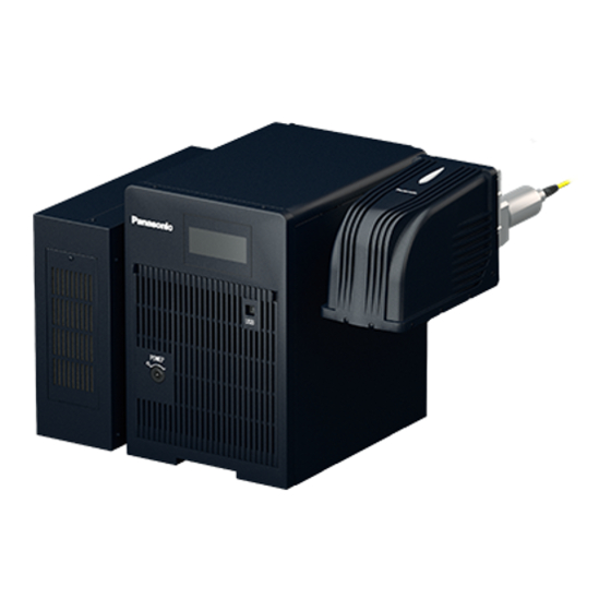
Laser Marking System
Laser Marker NAVI smart
Quick Reference
This guide describes the following basic procedures:
• How to start test marking
• How to create a marking data
For more information about the Laser Marker NAVI smart software,
refer to the "Laser Marker NAVI smart Operation Manual".
LP-GS series
LP-RC series
LP-RF series
LP-RV series
Table of Contents

Related Manuals for Panasonic NAVI smart


Summary of Contents for Panasonic NAVI smart
- Page 1 This guide describes the following basic procedures: • How to start test marking • How to create a marking data For more information about the Laser Marker NAVI smart software, refer to the “Laser Marker NAVI smart Operation Manual”. ME-NAVIS2-QR-1 2020.10...
-
Page 2: Preface
Preface Thank you for purchasing our product. For full use of this product safely and properly, please read this document carefully. This product has been strictly checked and tested prior to its delivery. However, please make sure that this product operates properly before using it. -
Page 3: How To Read This Document
How to Read this Document Symbol description “Notice” denotes any instructions or precautions for using this product. To prevent the damage or malfunction of the product, observe these precautions fully. “Reference” denotes any hints for operation, detail explanations, or references. ... - Page 4 • Maintenance details Laser Marker NAVI smart Operation Manual Instruction manual for the laser marker configuration software “Laser Marker NAVI smart”. This manual describes the procedure and method to operate the laser marker, and the screen operations to set marking contents.
-
Page 5: Table Of Contents
Contents Preface ……………………………………………………………………………… 2 How to Read this Document ……………………………………………………… 3 1 Laser Marker NAVI smart Basics ………………………………… 6 1-1 “Startup” screen ………………………………………………………………… 7 1-2 “Marking settings” screen ……………………………………………………… 8 1-3 “Monitor” screen ………………………………………………………………… 11 1-4 “Maintenance” screen ………………………………………………………… 13 1-5 “Data management”... -
Page 6: Laser Marker Navi Smart Basics
1 Laser Marker NAVI smart Basics ME-NAVIS2-QR-1... -
Page 7: Startup" Screen
1-1 “Startup” screen When you launch Laser Marker NAVI smart, the “Startup” screen appears. You can select the software application among “Online”, “Offline”, or “Convert”. User interface overview Item Description Menu With the menu tools, you can set the software preferences such as changing the user interface language and customizing user interface elements. -
Page 8: Marking Settings" Screen
1-2 “Marking settings” screen In this screen, you can create and edit marking data such as character, graphic and bar code objects and save them in a file. If you are logged in as “Restricted user”, only the parameters allowed to edit are available. You can do the following: •... - Page 9 Setting tools in the ribbon Item Description Open Select a marking file to open and edit in the “Marking settings” screen. Save Save the marking files to the connected laser marking system or to your PC. Undo / redo You can use these editing tools to revert the most recent operation.
- Page 10 Marking image editor The marking image editor is part of the “Marking settings” screen and the “Monitor” screen. Item Description File number and file The number and name of the selecting file are displayed in the tab. name Ruler The rulers appear on the top and left side of the marking image editor.
-
Page 11: Monitor" Screen
1-3 “Monitor” screen In this screen, you can monitor the operation status of the laser marking system during remote mode or RUN mode. You can do the following: • Check the marking image. • Check the marking settings. • Check the ON or OFF status of I/O terminals. ... - Page 12 Setting tools in the ribbon Item Description Open You can select and open a marking file on the “Monitor” screen. I/O monitor The status (“ON”/“OFF”) of the I/O terminals on the laser marking system is displayed. Refresh screen This button is available in the ribbon, if you select “Button “Refresh screen”” in “Startup” >...
-
Page 13: Maintenance" Screen
1-4 “Maintenance” screen This screen is used for the maintenance of the laser marking system. You can do the following: • Check the operating data. • Start laser radiation to measure the laser power (commercial power meter required). • Simulate output operation. •... - Page 14 Setting tools in the ribbon Item Description Save as TSV Exports the entries of the command history or erro log entries as a TSV file. Delete all Deletes all log entries of the command history or erro log. Output simulation Use the output simulation function to check the operation of external devices connected to the laser marking system by manually changing the status of an output.
-
Page 15: Data Management" Screen
1-5 “Data management” screen This screen lists all files that are currently saved on the laser marking system, including marking files, graphic files and font files. You can do the following: • Add or delete a marking file, graphic file, or font file. •... - Page 16 Setting tools in the ribbon Item Description Adds a marking file, graphic file, or font file to use it in the laser marking system. Save to PC Saves a selected file to your local or network drive. Copy, Paste, Delete To manage marking files, graphic files and font files, use the copy, paste, and delete functions.
-
Page 17: System Settings" Screen
1-6 “System settings” screen In this screen you set the system properties of the laser marking system. You can do the following: • Change the date and time of the system clock. • Make settings for communication with external devices. •... - Page 18 Setting tools in the ribbon Item Description Apply to laser marking Updates the system settings in the laser marking system. If any changes are made, “!” symbol is appeared on the icon. system System information Displays information about the laser marking system, such as version or serial number. Marking field You can adjust the marking field position when it is misaligned.
-
Page 19: Let's Use Laser Marker Navi Smart
2 Let's Use Laser Marker NAVI smart ME-NAVIS2-QR-1... - Page 20 Setting and operating procedures Follow the steps to configure marking settings and perform marking. A typical step by step example is given below. 1. Start Laser Marker NAVI smart 1) Start Laser Marker NAVI smart 2) Open a marking file to edit 2.
-
Page 21: Start Laser Marker Navi Smart
2-1 Start Laser Marker NAVI smart 2-1-1 Start Laser Marker NAVI smart Open the start menu and select “Panasonic-ID SUNX Laser” > “Laser Marker NAVI smart”. Laser Marker NAVI smart starts and displays the “Startup” screen. ME-NAVIS2-QR-1... -
Page 22: Open A Marking File To Edit
2-1-2 Open a marking file to edit Select “New...” > “Marking file (.lms)” and select the model of your laser marking system. In this example, LP-RF200P is selected. The “Marking settings” screen opens with an empty marking image editor. ME-NAVIS2-QR-1... -
Page 23: Create A Marking File (Offline Mode)
2-2 Create a marking file (offline mode) 2-2-1 Create a marking object Create marking objects and specify the desired marking settings. A typical procedures to set a marking object, for example character text “ABCD” are given below. Select “Character” > “Direct input” in the ribbon. In the dialog, enter the text for your character object. -
Page 24: Specify The Layout Of A Marking Object
2-2-2 Specify the layout of a marking object Typical procedures to set a marking object, for example to set character text “ABCD”, are given below. Character spacing: 5 mm Character height: 4 mm Character width: 4 mm X-position: -10 mm Y-position: 5 mm Open the “Object settings”... -
Page 25: Set Laser Parameters
2-2-3 Set laser parameters Specify laser parameters that apply to all objects in the marking file, such as laser power and scan speed. Open the “Laser settings” tab. Specify the value for “Laser power”. Laser power: 30.0 For test marking, it is recommended to set a lower laser power value. -
Page 26: Save Marking Data To Your Pc
2-3 Save marking data to your PC If you edit a marking file in offline mode, you must save it to your PC before you can transfer it to the laser marking system. In the “Marking settings” screen, select “Save” > “Save as” in the ribbon. Select the storage location, enter a file name and select “Save”. -
Page 27: Connect Your Pc And The Laser Marking System
NAVI smart. Connect the PC via USB to make these settings. • If the laser marking system supports Bluetooth, before you can make a Bluetooth connection, you must make the appropriate communication settings in Laser Marker NAVI smart. Connect the PC via USB to make these settings. ME-NAVIS2-QR-1... -
Page 28: Start The Laser Marking System
2-5 Start the laser marking system • In case of an emergency stop or an interlock, re-pumping of the laser marking WARNING system will be necessary. For safety reasons, construct a laser re-pumping system which must be operated by hand. Setup the laser marker connecting head, controller and interfaces. -
Page 29: Establish An Online Connection
2-6 Establish an online connection Select the “Connection” tool in the ribbon. Alternatively, go to the “Startup” screen and select “Online”. The “Connection” dialog appears. Select the laser marking system that you want to connect and select “Connect” to establish the connection. ME-NAVIS2-QR-1... -
Page 30: Transfer A Marking File From Your Pc To The Laser Marking System
2-7 Transfer a marking file from your PC to the laser marking system Go to the “Marking settings” screen and select “Open” > “From PC” in the ribbon. In the dialog, choose a marking file (.lms) from your local or network drive and select “Open”. A dialog opens and shows a list of all marking files saved on the laser marking system. - Page 31 The marking file is opened in the “Marking settings” screen. ME-NAVIS2-QR-1...
-
Page 32: Start Laser Radiation For Marking
2-8 Start laser radiation for marking 2-8-1 Check the marking position using the guide laser For LP-GS051, LP-GS051-L, LP-RC, LP-RF and LP-RV, you can use the guide laser to display the marking field, marking image, masked objects, or work distance. For LP-GS052, only the pointer is available as a guide laser function. Set your workpiece on the marking position. - Page 33 Select “Guide laser OFF” to stop the radiation of the guide laser. Select “Marking image” for “Guide laser display” and select “Guide laser ON” to start radiating the guide laser. Move the workpiece to the desired marking position. The guide laser indicates the marking image. Select “Guide laser OFF”...
-
Page 34: Turn Laser Pumping On
2-8-2 Turn laser pumping on Turn laser pumping on to enable the lasing process. Select the “Laser pumping” tool in the ribbon. In the confirmation dialog, select “Yes” to start laser pumping. A certain amount of time is required to complete laser pumping for the different laser marking systems: •... -
Page 35: Perform Test Marking
2-8-3 Perform test marking Select “Test marking” in the ribbon. In the dialog, check the values for the laser settings and change them if required. The available parameters depend on the model of your laser marking system. Select “Marking time” to perform the measurement. The marking time is displayed in the dialog. -
Page 36: Terminate The Operation
2-9 Terminate the operation To turn laser pumping off, select the “Laser pumping” tool in the “Laser pumping” tool ribbon. Laser pumping on Laser pumping off Select “Online” in the ribbon. Alternatively, go to the “Startup” screen and select “Online”. “Online”... -
Page 37: Create Various Marking Data
3 Create Various Marking Data ME-NAVIS2-QR-1... -
Page 38: Mark Date And Time
3-1 Mark date and time Set the functional characters to mark the automatically updated date and time. The procedures to set the current time are given below. Example Item Setting 13 29 Number of characters hour minute Date/time type Hour (24), Minute Zero indication Zero fill... - Page 39 Setting procedures In the “Marking settings” screen, select “Character” > “Direct input” in the ribbon. The “Character” dialog opens. Select “Functional characters”. The “Functional characters” dialog opens. Select the “Date/time” tab and specify the parameters of the functional character. •...
- Page 40 Select the “Date/time” tab and specify the parameters of the functional character. • Date/time: Current date/time • Number of characters: • Date/time type: Minute • Zero indication: Zero fill Select “OK”. In the input window, “%02:H0%02:m0” is displayed. Check the functional characters in the “Preview”...
-
Page 41: Mark 2D Code
3-2 Mark 2D code The procedures to set a QR Code are given below. Example Item Setting Code type QR Code, Model 2 Code data ABCDEFGHIJKLMN12345 Error correction level Module height Module height 0.500 mm Module width 0.500 mm Human readable text Disabled Module width... - Page 42 The entire width and height of the code, including the quiet zone are displayed in “Total width [mm]” and “Total height [mm]”. • For details of the QR code settings, refer to the “Laser Marker NAVI smart Operation Manual”. ME-NAVIS2-QR-1...
- Page 43 Set the filling pattern parameters for QR Code. • Filling pattern: Horizontal line • Filling width per module [mm]: 0.500 • Filling height per module [mm]: 0.500 If you do not mark the human readable text, set as follows: • Human readable text: Confirm that the QR code is displayed in the marking image editor.
-
Page 44: Mark A Graphic
3-3 Mark a graphic You can add graphic files created with AutoCAD or the Logo Data Editing software to use them in your marking file. The procedures to set a graphic are given below. Example Setting procedures In the “Marking settings” screen, select “Graphic” > “Graphic files” in the ribbon. - Page 45 Select the graphic to be inserted into the marking file and confirm with “OK”. The graphic is added and displayed in the marking image editor. If required, change the parameters in the graphic object settings and laser settings. Refer to “2-2 Create a marking file (offline mode)” (P.23). Perform the test marking.
- Page 46 Panasonic Industrial Devices SUNX Co., Ltd. https://panasonic.net/id/pidsx/global Please visit our website for inquiries and about our sales network. © Panasonic Industrial Devices SUNX Co., Ltd. 2020 October, 2020...