Table of Contents
Quick Links
Manual, Tool Changer, QC-113
Document #9620-20-B-113 Base Tool Changer-05
B. Base Tool Changer .................................................................................................................B-3
QC-113 Series-Tool Changer .....................................................................................................B-3
1.
Product Overview ..................................................................................................................B-3
1.1
Master Plate Assembly ............................................................................................................. B-4
1.2
Tool Plate Assembly .................................................................................................................. B-5
1.3
Optional Modules ...................................................................................................................... B-5
2.
Installation .............................................................................................................................B-6
2.1
Master Interface ......................................................................................................................... B-7
2.2
Master Plate Installation ........................................................................................................... B-8
2.3
Master Plate Removal ............................................................................................................... B-9
2.4
Tool Interface ........................................................................................................................... B-10
2.5
Tool Plate Installation ..............................................................................................................B-11
2.6
Tool Plate Removal ..................................................................................................................B-11
2.7
Pneumatic Requirements ....................................................................................................... B-12
2.7.1
Valve Requirements for Air Adapter Modules ................................................................B-12
2.8
Electrical Connections ............................................................................................................ B-13
2.8.1
NPN Type Lock and Unlock Sensors (-SP sensor designation) ....................................B-13
3.
Operation .............................................................................................................................B-14
3.1
Conditions for Coupling ......................................................................................................... B-15
3.2
Fail-Safe Operation ................................................................................................................. B-16
3.3
Conditions for Uncoupling ..................................................................................................... B-17
3.4
3.5
Tool Storage Considerations ................................................................................................. B-18
4.
Maintenance .........................................................................................................................B-18
4.1
Preventive Maintenance ......................................................................................................... B-19
4.2
Cleaning and Lubrication of the Locking Mechanism and Alignment Pins ....................... B-20
4.3
Pin Block Inspection and Cleaning ....................................................................................... B-22
5.
Troubleshooting ..................................................................................................................B-23
5.1
Troubleshooting Procedures ................................................................................................. B-23
5.2
Service Procedures ................................................................................................................. B-24
5.2.1
Alignment Pin Replacement ..........................................................................................B-24
5.2.2
Lock and Unlock Sensor Replacement Procedures ......................................................B-26
5.2.3
RTL Flat Pack Style Sensor Replacement (R2 Sensor) ................................................B-27
5.2.4
RTL Flat Pack Style Sensor Replacement (R1 Sensor) ................................................B-29
5.2.5
Seal Inspection and Replacement .................................................................................B-30
Pinnacle Park • 1031 Goodworth Drive • Apex, NC 27539 • Tel: 919.772.0115 • Fax: 919.772.8259 •
Table of Contents
B-1
www.ati-ia.com
Table of Contents

Related Manuals for ATI Technologies QC‑113


Summary of Contents for ATI Technologies QC‑113
-
Page 1: Table Of Contents
Manual, Tool Changer, QC‑113 Document #9620‑20‑B‑113 Base Tool Changer‑05 Table of Contents B. Base Tool Changer .........................B-3 QC-113 Series—Tool Changer .....................B-3 Product Overview ........................B-3 Master Plate Assembly ......................B-4 Tool Plate Assembly ........................B-5 Optional Modules ........................B-5 Installation ..........................B-6 Master Interface ......................... - Page 2 Manual, Tool Changer, QC‑113 Document #9620‑20‑B‑113 Base Tool Changer‑05 Serviceable Parts ........................B-31 Common Master Parts ......................B-31 Models 9121-113xM-0-0-0-0-SP ....................B-32 Tool plate ..........................B-33 7. Specifications ........................B-34 Drawings ..........................B-35 QC-113 Tool Changer ......................B-35 Pinnacle Park • 1031 Goodworth Drive • Apex, NC 27539 • Tel: 919.772.0115 • Fax: 919.772.8259 • www.ati‑ia.com...
-
Page 3: Base Tool Changer
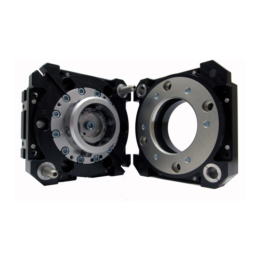
Manual, Tool Changer, QC‑113 Document #9620‑20‑B‑113 Base Tool Changer‑05 B. Base Tool Changer QC-113 Series—Tool Changer 1. Product Overview ATI Tool Changers enhance the versatility of a robot by enabling the use of multiple customer tools, such as: grippers, vacuum cup tooling, pneumatic and electric motors, weld guns, and more. The Tool Changer consists of a Master plate, which is attached to the robot arm, and a Tool plate, which is attached to customer tooling. -
Page 4: Master Plate Assembly
Manual, Tool Changer, QC‑113 Document #9620‑20‑B‑113 Base Tool Changer‑05 1.1 Master Plate Assembly The Master plate assembly includes an anodized aluminum body, a hardened stainless steel locking mechanism, and hardened steel alignment pins (see Figure 1.1). The body or Master plate has (4) flat sides for mounting of optional modules. In general, flat ‘A’ is reserved for an air/valve adapter module and a control/signal module. -
Page 5: Tool Plate Assembly
Manual, Tool Changer, QC‑113 Document #9620‑20‑B‑113 Base Tool Changer‑05 1.2 Tool Plate Assembly The Tool plate assembly includes an anodized aluminum body, alignment bushings, and a hardened stainless steel bearing race. The Tool plate has (4) flat sides for mounting of optional modules. Proximity sensor targets are mounted to the body of the Tool plate to verify Tool plate presence when coupled. -
Page 6: Installation
Manual, Tool Changer, QC‑113 Document #9620‑20‑B‑113 Base Tool Changer‑05 2. Installation All fasteners used to mount the Tool Changer to the robot and to customer’s tooling should be tightened to a torque value as indicated. Refer to Table 2.1. Furthermore, removable (blue) Loctite 242 must be used on these fasteners. -
Page 7: Master Interface
Manual, Tool Changer, QC‑113 Document #9620‑20‑B‑113 Base Tool Changer‑05 2.1 Master Interface The Master plate is typically attached to the robot arm. An interface plate can adapt the Master plate to a specific robot arm. Alignment features (dowel holes and bosses) accurately position and bolt holes secure the Master plate to the robot arm or an interface plate. -
Page 8: Master Plate Installation
Manual, Tool Changer, QC‑113 Document #9620‑20‑B‑113 Base Tool Changer‑05 2.2 Master Plate Installation Tools required: 8 mm hex key, torque wrench ® Supplies required: Clean rag, Loctite 1. Wipe down the mounting surfaces with a clean rag. 2. If required, install the interface plate to the robot arm, align using the boss or dowel pins and secure with customer supplied fasteners. -
Page 9: Master Plate Removal
Manual, Tool Changer, QC‑113 Document #9620‑20‑B‑113 Base Tool Changer‑05 2.3 Master Plate Removal Refer to Figure 2.1. Tools required: 8 mm hex key 1. Place the Tool in a secure location. 2. Uncouple the Master and Tool plates. 3. Turn off and de-energize all energized circuits (for example: electrical, pneumatic, and hydraulic circuits). -
Page 10: Tool Interface
Manual, Tool Changer, QC‑113 Document #9620‑20‑B‑113 Base Tool Changer‑05 2.4 Tool Interface The Tool plate is attached to the customer’s tooling. An interface plate can adapt the Tool plate to customer tooling. Alignment features (dowel holes and a recess) accurately position and bolt holes to secure the Tool plate to customer tooling. -
Page 11: Tool Plate Installation
Manual, Tool Changer, QC‑113 Document #9620‑20‑B‑113 Base Tool Changer‑05 2.5 Tool Plate Installation Tools required: 6 mm hex key, torque wrench Supplies required: Clean rag, Loctite 242 1. Wipe down the mounting surfaces with a clean rag. 2. If required, install the tool interface plate to the customer tooling, align using the boss or dowel pins and secure with customer supplied fasteners. -
Page 12: Pneumatic Requirements
Manual, Tool Changer, QC‑113 Document #9620‑20‑B‑113 Base Tool Changer‑05 2.7 Pneumatic Requirements Proper operation of the locking mechanism requires a constant supply of clean, dry, non-lubricated air, with the following conditions: • Pressure range of 60 to 100 psi (4.1 ‑ 6.9 bar) Suggested 80 psi. •... -
Page 13: Electrical Connections
Manual, Tool Changer, QC‑113 Document #9620‑20‑B‑113 Base Tool Changer‑05 2.8 Electrical Connections Tool Changer is available with integrated lock/unlock sensors. If sensors are not used, plugs will be provided to seal the locking mechanism. If a control/signal module is to be utilized on Flat A when ordered, the sensors will be connected to the module prior to shipping. -
Page 14: Operation
Manual, Tool Changer, QC‑113 Document #9620‑20‑B‑113 Base Tool Changer‑05 3. Operation The Master plate locking mechanism is pneumatically driven to couple and uncouple with the Tool plate bearing race. CAUTION: Operation of the Tool Changer is dependent on maintaining an air pressure of 60 to 100 psi (4.1 - 6.9 bar). -
Page 15: Conditions For Coupling
Manual, Tool Changer, QC‑113 Document #9620‑20‑B‑113 Base Tool Changer‑05 3.1 Conditions for Coupling The following conditions should be considered when operating the Tool Changer. For more details about programming the robot, refer to the Operation section of the Control/Signal Module Manual. CAUTION: Do not attempt to couple the Tool Changer when in locked position. -
Page 16: Fail-Safe Operation
Manual, Tool Changer, QC‑113 Document #9620‑20‑B‑113 Base Tool Changer‑05 6. A sufficient delay must be programmed between locking valve actuation and robot motion so that the locking process is complete before moving the robot. If equipped with Lock and Unlock sensors, the Lock signal should read “ON”... -
Page 17: Conditions For Uncoupling
Manual, Tool Changer, QC‑113 Document #9620‑20‑B‑113 Base Tool Changer‑05 3.3 Conditions for Uncoupling Refer to your Air/Valve Adapter and/or Control/Signal Module Manual’s Operation section for operation during coupling/uncoupling. 1. Move the robot to position the Tool plate in the tool stand. The position for coupling and uncoupling are the same. -
Page 18: Tool Storage Considerations
Manual, Tool Changer, QC‑113 Document #9620‑20‑B‑113 Base Tool Changer‑05 3.5 Tool Storage Considerations NOTICE: Tool stand design is critical to the operation of the Tool Changer. Improperly designed tool stands can cause jamming and excessive wear of the Tool Changer components. Tool plates with customer tooling attached may be stored in a tool stand. -
Page 19: Preventive Maintenance
Manual, Tool Changer, QC‑113 Document #9620‑20‑B‑113 Base Tool Changer‑05 4.1 Preventive Maintenance A visual inspection and preventive maintenance schedule is provided in table below. Detailed assembly drawings are Section 8—Drawings provided in of this manual. Refer to module sections for detailed preventive maintenance steps for all utility modules. -
Page 20: Cleaning And Lubrication Of The Locking Mechanism And Alignment Pins
Manual, Tool Changer, QC‑113 Document #9620‑20‑B‑113 Base Tool Changer‑05 4.2 Cleaning and Lubrication of the Locking Mechanism and Alignment Pins ® Supplies required: Clean rag, MobilGrease XHP222 Special Grease 1. Place the Tool in a secure location. 2. Uncouple the Master and Tool plates. 3. - Page 21 Manual, Tool Changer, QC‑113 Document #9620‑20‑B‑113 Base Tool Changer‑05 6. Check each ball bearing to make sure it moves freely in the male coupling. Additional cleaning may be necessary to free up any ball bearings that are sticking in place. Figure 4.3—Check Ball Bearing Movement 7.
-
Page 22: Pin Block Inspection And Cleaning
Manual, Tool Changer, QC‑113 Document #9620‑20‑B‑113 Base Tool Changer‑05 4.3 Pin Block Inspection and Cleaning Tools required: Nylon Brush (ATI Part Number 3690‑0000064‑60) 1. Place the Tool in a secure location. 2. Uncouple the Master and Tool plates. 3. Turn off and de-energize all energized circuits (for example: electrical, pneumatic, and hydraulic circuits). -
Page 23: Troubleshooting
Manual, Tool Changer, QC‑113 Document #9620‑20‑B‑113 Base Tool Changer‑05 5. Troubleshooting The following section provides troubleshooting and service information to help diagnose conditions and repair the Tool Changer or control/signal module. WARNING: Do not perform maintenance or repair(s) on the Tool Changer or modules unless the Tool is safely supported or placed in the tool stand, all energized circuits (e.g. -
Page 24: Service Procedures
Manual, Tool Changer, QC‑113 Document #9620‑20‑B‑113 Base Tool Changer‑05 5.2 Service Procedures The following service procedures provide instructions for component replacement. 5.2.1 Alignment Pin Replacement Parts required: Refer to Section 6—Serviceable Parts Tools required: 3 mm and 4 mm hex key socket, torque wrench Supplies required: Clean rag, MobilGrease XHP222, Loctite 242 1. - Page 25 Manual, Tool Changer, QC‑113 Document #9620‑20‑B‑113 Base Tool Changer‑05 Figure 5.2—Remove Alignment Pin From Back Side Master Plate 3 mm Hex Key Socket Ratchet Wrench Set Screw Alignment Pin Assembly 6. Once the alignment pin has been removed, verify that the assembly (pin and set screw) are intact.
-
Page 26: Lock And Unlock Sensor Replacement Procedures
Manual, Tool Changer, QC‑113 Document #9620‑20‑B‑113 Base Tool Changer‑05 5.2.2 Lock and Unlock Sensor Replacement Procedures Parts required: Refer to Section 6—Serviceable Parts Tools required: 2 mm, 2.5 mm, 3 mm, and 5 mm hex keys, torque wrench 1. Place the Tool in a secure location. 2. -
Page 27: Rtl Flat Pack Style Sensor Replacement (R2 Sensor
Manual, Tool Changer, QC‑113 Document #9620‑20‑B‑113 Base Tool Changer‑05 12. Secure the sensor assembly using the (2) M3 socket flat head screws using a 2.5 mm hex key. Tighten to 12 in-lbs (1.4 Nm). 13. Route the sensor cable on Flat A with the cable clip to secure to the Tool Changer body using the M5 button head cap screw with a 3 mm hex key. - Page 28 Manual, Tool Changer, QC‑113 Document #9620‑20‑B‑113 Base Tool Changer‑05 Figure 5.5— RTL Sensor Replacement (R2 Sensor) M3 Socket Head Cap Screw RTL Flat Pack Style Sensor M6 Socket Head Cap Screws Valve Adapter/Control Module Connects to "R2" (2) Cable Retaining Tabs M3 Socket Head Cap Screws Remove Module from Flat D 8.
-
Page 29: Rtl Flat Pack Style Sensor Replacement (R1 Sensor
Manual, Tool Changer, QC‑113 Document #9620‑20‑B‑113 Base Tool Changer‑05 5.2.4 RTL Flat Pack Style Sensor Replacement (R1 Sensor) Parts required: Refer to Section 6—Serviceable Parts Tools required: 2 mm hex key, torque wrench 1. Place the Tool in a secure location. 2. -
Page 30: Seal Inspection And Replacement
Manual, Tool Changer, QC‑113 Document #9620‑20‑B‑113 Base Tool Changer‑05 9. Install the new RTL sensor, routing the cable into the cable channel of the Valve Adapter/ Control Module. 10. Route the RTL sensor cable in the channel on the Valve Adapter/Control Module. 11. -
Page 31: Serviceable Parts
Manual, Tool Changer, QC‑113 Document #9620‑20‑B‑113 Base Tool Changer‑05 6. Serviceable Parts 6.1 Common Master Parts Table 5.2—Common Master Parts Item No. Part Number Description 9121-113xMX-0-0-0-0 Complete QC-113 Master plate, No Options 9005-20-2241 7/8” Two Piece Alignment Pin Cable Holder, Two-Line, 5/32”-1/4” OD, Plastic, M3 Flat 3690-0000084-01 Head Socket Cap Screw Attachment M3 x 12 mm Socket Flat Head Cap Screw Blue Dyed... -
Page 32: Models 9121-113Xm-0-0-0-0-Sp
Manual, Tool Changer, QC‑113 Document #9620‑20‑B‑113 Base Tool Changer‑05 6.2 Models 9121-113xM-0-0-0-0-SP Table 5.3—9121-113xM-0-0-0-0-SP Item No. Part Number Description 8590-9909999-198 LED NPN Flat Pack Sensor .28M (90 Pico) 8590-9909999-199 LED NPN Flat Pack Sensor .30M (90 Pico) 3500-1258010-11 M3 x 10 mm Socket Flat Head Cap Screw Black Oxide 9005-20-1744 Lock/Unlock Sensor Assembly, QC-210 (NPN) includes (2) of item 5 M3 X 8 Socket Head Cap Screw Blue Dyed Magni-565, ND... -
Page 33: Tool Plate
Manual, Tool Changer, QC‑113 Document #9620‑20‑B‑113 Base Tool Changer‑05 6.3 Tool plate Table 5.4— Tool plate Item No. Part Number Description 9121-113xT-0-0-0-0 QC-113 Base Tool Assembly, No Options Notes: x = A, B, C, D, E, or F for boss size designation. Pinnacle Park •... -
Page 34: Specifications
Manual, Tool Changer, QC‑113 Document #9620‑20‑B‑113 Base Tool Changer‑05 7. Specifications Table 5.5—Master and Standard Tool Plates Recommended Max Payload 220 lbs (100kg) The mass attached to the Tool Changer. -20–150°F Operating Temperature Range Operating Temperature (-30–66°C) Locking mechanism supply pressure 60–100 psi Operating Pressure Range operating range. -
Page 35: Drawings
Manual, Tool Changer, QC‑113 Document #9620‑20‑B‑113 Base Tool Changer‑05 8. Drawings 8.1 QC-113 Tool Changer Pinnacle Park • 1031 Goodworth Drive • Apex, NC 27539 • Tel: 919.772.0115 • Fax: 919.772.8259 • www.ati‑ia.com B-35... - Page 36 Manual, Tool Changer, QC‑113 Document #9620‑20‑B‑113 Base Tool Changer‑05 Pinnacle Park • 1031 Goodworth Drive • Apex, NC 27539 • Tel: 919.772.0115 • Fax: 919.772.8259 • www.ati‑ia.com B-36...
- Page 37 Manual, Tool Changer, QC‑113 Document #9620‑20‑B‑113 Base Tool Changer‑05 Pinnacle Park • 1031 Goodworth Drive • Apex, NC 27539 • Tel: 919.772.0115 • Fax: 919.772.8259 • www.ati‑ia.com B-37...