Table of Contents
Quick Links
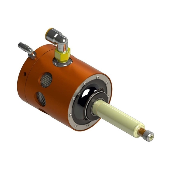
ATI Radially‑Compliant Robotic Deburring Tools
Flexdeburr™
(Models 9150‑RC‑660‑ER and 9150‑RC‑660‑ER‑E)
Manual
US Patent # 6,974,286 B2
Document #: 9610‑50‑1017
Engineered Products for Robotic Productivity
Pinnacle Park • 1031 Goodworth Drive • Apex, NC 27539 USA • Tel: +1.919.772.0115 • Fax: +1.919.772.8259 • www.ati‑ia.com
Table of Contents

Related Manuals for ATI Technologies Flexdeburr RC-660 Series


Summary of Contents for ATI Technologies Flexdeburr RC-660 Series
- Page 1 ATI Radially‑Compliant Robotic Deburring Tools Flexdeburr™ (Models 9150‑RC‑660‑ER and 9150‑RC‑660‑ER‑E) Manual US Patent # 6,974,286 B2 Document #: 9610‑50‑1017 Engineered Products for Robotic Productivity Pinnacle Park • 1031 Goodworth Drive • Apex, NC 27539 USA • Tel: +1.919.772.0115 • Fax: +1.919.772.8259 • www.ati‑ia.com...
-
Page 2: Foreword
Manual, Flexdeburr, RC‑660 Series Document #9610‑50‑1017‑10 Foreword CAUTION: This manual describes the function, application, and safety considerations of this product. This manual must be read and understood before any attempt is made to install or operate this product. Failure to do so may result in personnel injury and/or damage to equipment. Information contained in this document is the property of ATI Industrial Automation, Inc (ATI) and shall not be reproduced in whole or in part without prior written approval of ATI. -
Page 3: Table Of Contents
Manual, Flexdeburr, RC‑660 Series Document #9610‑50‑1017‑10 Table of Contents Foreword ............................2 Glossary ............................5 Safety ............................6 1.1 Explanation of Notifications ......................6 General Safety Guidelines ......................6 Safety Precautions ........................7 Product Overview ........................8 Tool Collet Systems ........................8 Deburring Tool Part Numbers ...................... - Page 4 Manual, Flexdeburr, RC‑660 Series Document #9610‑50‑1017‑10 Maintenance ..........................24 Pneumatics ..........................24 Lubrication ........................... 24 Spindle Boot Inspection ......................24 Bur Inspection ..........................24 Spindle Motion Inspection ......................24 Troubleshooting and Service Procedures ................25 Troubleshooting .......................... 25 Service Procedures ........................27 6.2.1 Bur and Collet Replacement ....................
-
Page 5: Glossary
Manual, Flexdeburr, RC‑660 Series Document #9610‑50‑1017‑10 Glossary Definition Term Device for attaching the deburring tool to either a robot flange or a stationary Adapter Plate mounting surface. Device for removing contamination from air supply lines. Typically refers to Air Filter removal of particulates. -
Page 6: Safety
Manual, Flexdeburr, RC‑660 Series Document #9610‑50‑1017‑10 1. Safety The safety section describes general safety guidelines to be followed with this product, explanations of the notifications found in this manual, and safety precautions that apply to the product. More specific notifications are imbedded within the sections of the manual (where they apply). -
Page 7: Safety Precautions
Manual, Flexdeburr, RC‑660 Series Document #9610‑50‑1017‑10 1.3 Safety Precautions WARNING: Never operate the Flexdeburr product without wearing hearing protection. High sound levels can occur during cutting. Failure to wear hearing protect can cause hearing impairment. Always use hearing protection while working in the proximity of the deburring tool. -
Page 8: Product Overview
Manual, Flexdeburr, RC‑660 Series Document #9610‑50‑1017‑10 2. Product Overview The Radially‑Compliant (RC) deburring tool, also known as Flexdeburr, is a turbine‑driven deburring unit for deburring aluminum, plastic, steel, etc. with a robot or CNC machine. The RC Deburring Tool is especially suited for removal of parting lines and flash from parts. -
Page 9: Deburring Tool Part Numbers
Manual, Flexdeburr, RC‑660 Series Document #9610‑50‑1017‑10 The ATI RC‑660‑ER uses an ER‑11 collet system to hold cutting tools. The ER collet is a commercial, double‑angle design offering greater tool gripping force, less tool runout and an extended grip range. The collets are available from many sources in many different gripping diameters. -
Page 10: Technical Description
Manual, Flexdeburr, RC‑660 Series Document #9610‑50‑1017‑10 2.3 Technical description The technical overview of the product is provided in the following tables and graphs. For additional technical specifications, refer to Section 8—Specifications. 2.3.1 Environmental Limitations 2.3.1.1 Operation Table 2.1—Operation Mounted to robot using the side mounting pattern or rear adapter flange. - Page 11 Manual, Flexdeburr, RC‑660 Series Document #9610‑50‑1017‑10 Figure 2.3—RC‑660‑ER Series Radial Compliance Force Curves (Measured at the Spindle Tip) RC-660 Series Radial Contact Force Centering Air Pressure (Bar) RC-660 Series Radial Contact Force Centering Air Pressure (PSI) Pinnacle Park • 1031 Goodworth Drive • Apex, NC 27539 USA • Tel: +1.919.772.0115 • Fax: +1.919.772.8259 • www.ati‑ia.com...
-
Page 12: Installation
Manual, Flexdeburr, RC‑660 Series Document #9610‑50‑1017‑10 3. Installation The RC‑660‑ER Deburring Tool is delivered fully assembled. Optional equipment such as: mounting adapter plates, burs, and additional collets are separate. 3.1 Transportation and Protection During Transportation The RC deburring tool is packaged in a crate designed to secure and protect it during transportation. Always use the crate when transporting the deburring tool in order to minimize the risk of damage. -
Page 13: Side Mounting Installation
Manual, Flexdeburr, RC‑660 Series Document #9610‑50‑1017‑10 3.5 Side Mounting Installation The side mounting pattern of the RC deburring tool consists of (2) dowel pin holes and a number of threaded holes as shown in the following figure. The maximum fastener length specified must not be exceeded, or the fasteners interfere with the compliant motion of the turbine motor spindle. -
Page 14: Axial Mounting Installation
Manual, Flexdeburr, RC‑660 Series Document #9610‑50‑1017‑10 3.6 Axial Mounting Installation A blank robot adapter plate is also available to allow axial mounting off the rear of the deburring tool housing. This plate may be modified by the system integrator or by the owner/user of the Flexdeburr. ATI can provide custom interface plates and adapters upon request. -
Page 15: Pneumatics
Manual, Flexdeburr, RC‑660 Series Document #9610‑50‑1017‑10 3.7 Pneumatics Connect the RC deburring tool as shown in Figure 3.3. Figure 3.3—Pneumatic Connections SPINDLE AIR SOLENOID VALVE (2-WAY) HIGH-FLOW REGULATOR 6.2 BAR [90 PSI] FILTER SPINDLE MOTOR SUPPLY AIR: VENT TO CLEAN, DRY, ATMOSPHERE NON-LUBRICATED 6.9 BAR MIN. - Page 16 Manual, Flexdeburr, RC‑660 Series Document #9610‑50‑1017‑10 If the complete work piece can be deburred with equal force, a conventional, manual pressure regulator can be used for compliance. If the burrs to be removed vary from place to place on the work piece, and this variation is repeatable for all work pieces of the same type, it may be necessary to adjust the force using an analog pressure regulator controlled from the robot.
-
Page 17: Operation
Manual, Flexdeburr, RC‑660 Series Document #9610‑50‑1017‑10 4. Operation These operating instructions are intended to help system integrators program, start up, and complete a robotic deburring cell containing a deburring tool. The system integrator should be familiar with the task of deburring, in general, and should have extensive knowledge relating to robots and automation incorporating robots. -
Page 18: Air Quality
Manual, Flexdeburr, RC‑660 Series Document #9610‑50‑1017‑10 4.2 Normal Operation The following sections describes the normal operating conditions for RC deburring tools. 4.2.1 Air Quality The air supply should be dry, filtered, and free of oil. A coalescing filter with elements rated for 5 micron or better is required. -
Page 19: Flexdeburr Working Environment
Manual, Flexdeburr, RC‑660 Series Document #9610‑50‑1017‑10 4.3 Flexdeburr Working Environment As described in previous sections, the RC deburring tool should only be used in conjunction with a robot in a secured work cell/chamber. The work cell must be secured by means of barriers to prohibit personnel from entering the cell. A lockable door should be included as a part of the barrier in order to facilitate access to the cell for authorized personnel only. - Page 20 Manual, Flexdeburr, RC‑660 Series Document #9610‑50‑1017‑10 Another programming method is to teach the path using the centerline of the bur as a guide, following the edge of the part, and then manually or automatically adding offsets to the robot path points to achieve the final correct bur path (see Figure 4.2).
-
Page 21: Cutter Operation And Bur Selection
Manual, Flexdeburr, RC‑660 Series Document #9610‑50‑1017‑10 Interior corners represent a complex situation for compliant deburring tools. In general, the cutter must not be allowed to simultaneously contact both perpendicular surfaces of an interior corner. The resulting force imbalance in two planes will cause severe tool chatter. The customer is advised to create a tool path that prevents the cutter from simultaneously contacting two perpendicular surfaces. - Page 22 Manual, Flexdeburr, RC‑660 Series Document #9610‑50‑1017‑10 This following table is not comprehensive but includes many common bur types and burs recommended for particular applications. Table 4.1—Bur Selection Features/Benefits: Materials/Application 9150‑RC‑B‑24033 ‑ Diamond Cut, 1/4” Bur Diameter, 5/8” Bur Length, 1/4” Shank For hardened and tough Higher cutting capacity than •...
- Page 23 Manual, Flexdeburr, RC‑660 Series Document #9610‑50‑1017‑10 Table 4.1—Bur Selection Features/Benefits: Materials/Application 9150‑RC‑B‑26408 ‑ Cut FVK, 1/4” Bur Diameter, 5/8” Bur Length, 1/4” Shank For trimming and contour milling Special cut geometry allows • • of all glass and carbon fiber high feed rates due to low reinforced plastics.
-
Page 24: Maintenance
Manual, Flexdeburr, RC‑660 Series Document #9610‑50‑1017‑10 5. Maintenance The RC deburring tool provides long life with regular maintenance. The preventive maintenance of the deburring tool consists of cleaning the unit and regular inspection for wear or damage to the pneumatic lines, filter element, spindle boot, and bur. -
Page 25: Troubleshooting And Service Procedures
Manual, Flexdeburr, RC‑660 Series Document #9610‑50‑1017‑10 6. Troubleshooting and Service Procedures For all service, the air supply (before the solenoid valves) must be disconnected. Drain any trapped air pressure in the lines. It is suggested that the air supply be “locked out” to prevent accidental operation of the spindle. Refer to for maintenance instructions. - Page 26 Manual, Flexdeburr, RC‑660 Series Document #9610‑50‑1017‑10 Table 6.1—Troubleshooting Symptom Cause Resolution Incorrect feed rate Reduce feed rate. Too heavy a cut Decrease width of cut/make multiple passes. Choose bur designed for work material. Refer to Improper Bur selection Secondary burrs Section 4.5.1—Bur Selection.
-
Page 27: Service Procedures
Manual, Flexdeburr, RC‑660 Series Document #9610‑50‑1017‑10 6.2 Service Procedures Component replacement and adjustment procedures are provided in the following section. CAUTION: Thread locker applied to fasteners must not be used more than once. Fasteners might become loose and cause equipment damage. Always apply new thread locker when reusing fasteners. - Page 28 Manual, Flexdeburr, RC‑660 Series Document #9610‑50‑1017‑10 Figure 6.1—Bur and Collet Replacement 10 mm Open‑end Wrench Measure and record Spindle shaft Replace with the length of the bur new bur extend extending beyond beyond collet to the collet nut recorded length Collet Collet nut 7/16"...
-
Page 29: Turbine Motor Replacement
Manual, Flexdeburr, RC‑660 Series Document #9610‑50‑1017‑10 6.2.2 Turbine Motor Replacement If the turbine motor is operated using oil‑laden or dirty air, it will fail and require replacement. Failure of the motor due to contamination in the spindle air is not covered under warranty. The motor may also require replacement after an extended operating life or following a severe collision. - Page 30 Manual, Flexdeburr, RC‑660 Series Document #9610‑50‑1017‑10 Figure 6.2—Spindle Supply Fitting and Garter Spring Removal [2,6] Spindle Supply Fitting Assembly [#] Indicates the associated step number(s) in the procedure. [7] Internal Retaining Ring Rubber Disk [7] [8] Garter Spring Rear Housing Assembly [5] Compliance [2] Air Fitting...
- Page 31 Manual, Flexdeburr, RC‑660 Series Document #9610‑50‑1017‑10 13. To install the new motor, apply a thin coating of Magnalube or equivalent to the outer surface of the motor contact sleeve. 14. Gently insert the new turbine motor assembly into the front housing assembly and through the ring cylinder.
- Page 32 Manual, Flexdeburr, RC‑660 Series Document #9610‑50‑1017‑10 21. Apply Loctite 242 to the threads of the M8 socket button head cap screw. 22. Insert the washer and using a 5 mm hex key, thread the M8 socket button head screw into the rear of the turbine motor.
-
Page 33: Ring Cylinder Assembly Replacement
Manual, Flexdeburr, RC‑660 Series Document #9610‑50‑1017‑10 6.2.3 Ring Cylinder Assembly Replacement The compliant motion of the turbine motor spindle is accomplished using an array of pistons (ring cylinder) installed inside the front housing. After extended operation, this component may need to be replaced to ensure free motion of the pistons. - Page 34 Manual, Flexdeburr, RC‑660 Series Document #9610‑50‑1017‑10 5. Press the ring cylinder out of the front housing using a non‑metallic drift (plastic or wooden rod). Note: After prolonged periods of use, the O‑ring seals may impede removal of the compliance unit. If this occurs, support the front of the housing on a suitable plate with a clearance hole for the ring cylinder and use an arbor press for extraction.
-
Page 35: Rear Housing Assembly And Pivot Bearing Replacement
Manual, Flexdeburr, RC‑660 Series Document #9610‑50‑1017‑10 11. Fit the retaining ring into the groove in the front housing assembly to secure the ring cylinder. 12. Align the spindle boot and the boot ring with the holes in the ring cylinder. 13. - Page 36 Manual, Flexdeburr, RC‑660 Series Document #9610‑50‑1017‑10 5. Using a 5 mm hex key, remove the M8 socket button head cap screw and washer from the center of the deburring unit’s rear housing assembly. Refer to Figure 6.11. 6. Using a 3 mm hex key, remove the (6) M4 socket head cap screws that secure the rear housing assembly to the front housing assembly.
- Page 37 Manual, Flexdeburr, RC‑660 Series Document #9610‑50‑1017‑10 Figure 6.12—Pivot Bearing Removal [13,14] Pivot Bearing Keying Dowel M5 Set Screw [13] [15] Press Tool [12] Loosen the Bearing Preload Set Screw M5 Set Screw [13] [10,12,13] Rear Housing Assembly [15] Pivot Bearing [11] Large Clamping Washer [10] (3) M4 Socket Head Cap Screws 16.
- Page 38 Manual, Flexdeburr, RC‑660 Series Document #9610‑50‑1017‑10 21. Still holding the pivot ball in the rotated position, use a 2.5 mm hex key to insert the second M5 set screw into the rear housing to secure the keying dowel pin in place. 22.
- Page 39 Manual, Flexdeburr, RC‑660 Series Document #9610‑50‑1017‑10 26. Apply a thin coating of Magnalube to the alignment pin and o‑ring included with the new rear housing assembly. Insert the pin and o‑ring into the front housing as shown in Figure 6.16. 27.
- Page 40 Manual, Flexdeburr, RC‑660 Series Document #9610‑50‑1017‑10 30. Install the deburring tool to the robot or work location. 31. Connect the air hose to the spindle supply fitting and the compliance air fitting. 32. Adjust the pivot bearing preload set screw if necessary. Supply 10 psi to the compliance air fitting.
-
Page 41: Spindle Boot Replacement
Manual, Flexdeburr, RC‑660 Series Document #9610‑50‑1017‑10 6.2.5 Spindle Boot Replacement The spindle boot prevents debris from entering the housing and protects internal components. Replace the spindle boot if damaged. Refer to Figure 6.18 Figure 6.19. Parts required: Refer to Section 7—Serviceable Parts. - Page 42 Manual, Flexdeburr, RC‑660 Series Document #9610‑50‑1017‑10 8. Align the spindle boot and the boot ring with the holes in the ring cylinder. 9. Slide the boot onto the turbine motor and align the edge of the boot to the edge of the contact sleeve.
-
Page 43: Serviceable Parts
Manual, Flexdeburr, RC‑660 Series Document #9610‑50‑1017‑10 7. Serviceable Parts for exploded drawings showing For repair and spare parts, please contact ATI. Refer to Section 9—Drawings all the user replaceable components of the Flexdeburr. Available accessories, tools, and optional replacement Section 7.1—Accessories Tools, and Optional Replacement Parts. parts are listed in All other repairs must be performed by ATI. -
Page 44: Specifications
Manual, Flexdeburr, RC‑660 Series Document #9610‑50‑1017‑10 8. Specifications Table 8.1—Specifications Parameter Rating Motor Turbine Motor Part Number 3490‑0001038‑02 Motor Series 210JSL Idle Speed (RPM) 40,000 (44,000 Max.) Torque (Max. Power) 0.16 N‑m (1.4 lb‑in) Power (0.88 hp) @ 40,000 RPM Weight (without Adapters) 2.2 kg (4.9 lb) Compensation (Radial) -
Page 45: Drawings
Manual, Flexdeburr, RC‑660 Series Document #9610‑50‑1017‑10 9. Drawings Pinnacle Park • 1031 Goodworth Drive • Apex, NC 27539 USA • Tel: +1.919.772.0115 • Fax: +1.919.772.8259 • www.ati‑ia.com... - Page 46 Manual, Flexdeburr, RC‑660 Series Document #9610‑50‑1017‑10 Pinnacle Park • 1031 Goodworth Drive • Apex, NC 27539 USA • Tel: +1.919.772.0115 • Fax: +1.919.772.8259 • www.ati‑ia.com...
- Page 47 Manual, Flexdeburr, RC‑660 Series Document #9610‑50‑1017‑10 Pinnacle Park • 1031 Goodworth Drive • Apex, NC 27539 USA • Tel: +1.919.772.0115 • Fax: +1.919.772.8259 • www.ati‑ia.com...
-
Page 48: Terms And Conditions Of Sale
Manual, Flexdeburr, RC‑660 Series Document #9610‑50‑1017‑10 10. Terms and Conditions of Sale The following Terms and Conditions are a supplement to and include a portion of ATI’s Standard Terms and Conditions, which are on file at ATI and available upon request. ATI warrants the compliant tool product will be free from defects in design, materials, and workmanship for a period of one (1) year from the date of shipment and only when used in compliance with the manufacturer’s specified normal operating conditions. -
Page 49: Motor Life And Service Interval Statement
Manual, Flexdeburr, RC‑660 Series Document #9610‑50‑1017‑10 10.1 Motor Life and Service Interval Statement The air motors that are used in ATI deburring/finishing tools are subject to wear and have a finite life. Motors that fail, during the warranty period, will be repaired or replaced by ATI as lon as there is no evidence of abuse or neglect and that the normal operating practices outlined in this manual have been observed.