
Related Manuals for Emerson PACMotion IC830DP00306


Summary of Contents for Emerson PACMotion IC830DP00306
- Page 1 Installation and User Manual GFK-3168A September 2020 PACMotion™ PSD INSTALLATION AND USER MANUAL 903-200003-EMR1...
- Page 3 Changes, modifications, and/or improvements to equipment and specifications are made periodically and these changes may or may not be reflected herein. It is understood that Emerson may make changes, modifications, or improvements to the equipment referenced herein or to the document itself at any time. This document is intended for trained personnel familiar with the Emerson products referenced herein.
-
Page 4: Table Of Contents
PACMotion™ PSD Installation and User Manual Contents GFK-3168A September 2020 Contents Section 1 Introduction ............1 Document Revisions .................... 1 About this manual ....................1 Safety ........................1 1.3.1 You should pay attention to this ..............1 1.3.2 Specialist staff required! ................1 1.3.3 Read the documentation! ................ - Page 5 PACMotion™ PSD Installation and User Manual Contents GFK-3168A September 2020 4.1.6 Full digital control ................... 12 4.1.7 Inputs/Outputs ..................12 4.1.8 Connectivity .................... 12 Ambient Conditions, Ventilation, and Mounting Position ........13 Mechanical Data ....................13 Inputs/Outputs ....................14 Electrical Data IC830DPzzz06 ................14 Electrical Data IC830DPzzz07 ................
- Page 6 PACMotion™ PSD Installation and User Manual Contents GFK-3168A September 2020 4.17 Shock-hazard Protection ................... 43 4.17.1 Leakage current ..................43 4.17.2 Residual current protective device (RCD) ..........44 4.17.3 Isolating transformers ................44 Section 5 Mechanical Installation ........45 Important Notes ....................45 Guide to Mechanical Installation ................
- Page 7 PACMotion™ PSD Installation and User Manual Contents GFK-3168A September 2020 5.18 Service Interface (X11) ..................90 5.18.1 Pinout X11 ....................90 5.18.2 Service Bus Protocols X11 ................ 90 5.18.3 Possible Network Configurations ............. 91 5.18.4 Setting the IP Address IC830DP ............... 91 5.19 EtherCat Interface (X5/X6/EtherCat) ..............
-
Page 8: Introduction
About this manual This manual provides the technical descriptions and adjustments available for the PSR series of synchronous servomotors. The motors are operated in drive systems together with Emerson servo amplifiers. Please observe the entire system documentation, consisting of: Instructions manual for the servo amplifier: •... -
Page 9: Read The Documentation
PACMotion™ PSD Installation and User Manual Section 1 GFK-3168A September 2020 1.3.3 Read the documentation! Read the available documentation before installation and commissioning. Improper handling of the devices can cause harm to people or damage to property. The operator of systems using the drive system must ensure that all personnel who work with the drive read and under- stand the manual before using the drive. -
Page 10: Earthing
Thermal sensors, motor holding brakes and feedback systems built into the connected motor must have reinforced insulation (according to IEC61800-5-1) against system components with power voltage, according to the required application test voltage. All Emerson components meet these requirements. 1.4.2.2 Never modify the drive! It is not allowed to modify the drive hardware without permission by the manufacturer. - Page 11 1.4.3.3 For the cases of group installations and of DC powered drives PSD has not been evaluated by Emerson, UL, or TÜV for group installations nor are ratings defined for DC input voltage. Group installations must be reviewed and evaluated by the user for branch circuit protection*, wire size, wire voltage rating, fuse protection, system dielectric requirements, overvoltage and input** current rating.
-
Page 12: Prohibited Use
PACMotion™ PSD Installation and User Manual Section 1 GFK-3168A September 2020 1.4.4 Prohibited Use Other use than that described in chapter “Use as directed” is not intended and can lead to personnel injuries and equipment damage. The drive may not be used with a machine that does not comply with appropriate national directives or standards. -
Page 13: Product Life Cycle Handling
PACMotion™ PSD Installation and User Manual Section 2 GFK-3168A September 2020 Section 2 Product Life Cycle Handling Transport Transport the PSD in accordance with IEC 61800-2 as follows: Transport only by qualified personnel in the manufacturer’s original recyclable packaging. Avoid shocks while transporting. -
Page 14: Capacitor Storage
PACMotion™ PSD Installation and User Manual Section 2 GFK-3168A September 2020 • Storage only within specified humidity: 5 to 95% relative humidity, no condensation, class 1K3. • Store in accordance with the following duration requirements: Less than 1 year: without restriction. More than 1 year: capacitors must be re-formed before setting up and operating the drive. -
Page 15: Decommissioning
PACMotion™ PSD Installation and User Manual Section 2 GFK-3168A September 2020 Decommissioning Note: Only professional staff who are qualified in electrical engineering are allowed to decommission parts of the system. DANGER LETHAL VOLTAGES! There is a danger of serious personal injury or death by electrical shock or electrical arcing. •... -
Page 16: System Repair
PACMotion™ PSD Installation and User Manual Section 2 GFK-3168A September 2020 System Repair Note: Only professional staff who are qualified in electrical engineering are allowed to exchange parts of the drive system. DANGER AUTOMATIC START! During replacement work a combination of hazards and multiple episodes may occur. Work on the electrical installation may only be performed by trained and qualified personnel, in compliance with the regulations for safety at work, and only with use of prescribed personal safety equipment. -
Page 17: Package Supplied
PACMotion™ PSD Installation and User Manual Section 3 GFK-3168A September 2020 Section 3 Package Supplied • DVD with the Setup software Workbench and product documentation. • Various mating connectors and earthing plates Note: The mating SubD and RJ45 connectors are not included in the package. Part Number Scheme Use the part number scheme for product identification only, not for the order process, because not all combinations of features are possible, always. -
Page 18: Technical Description And Data
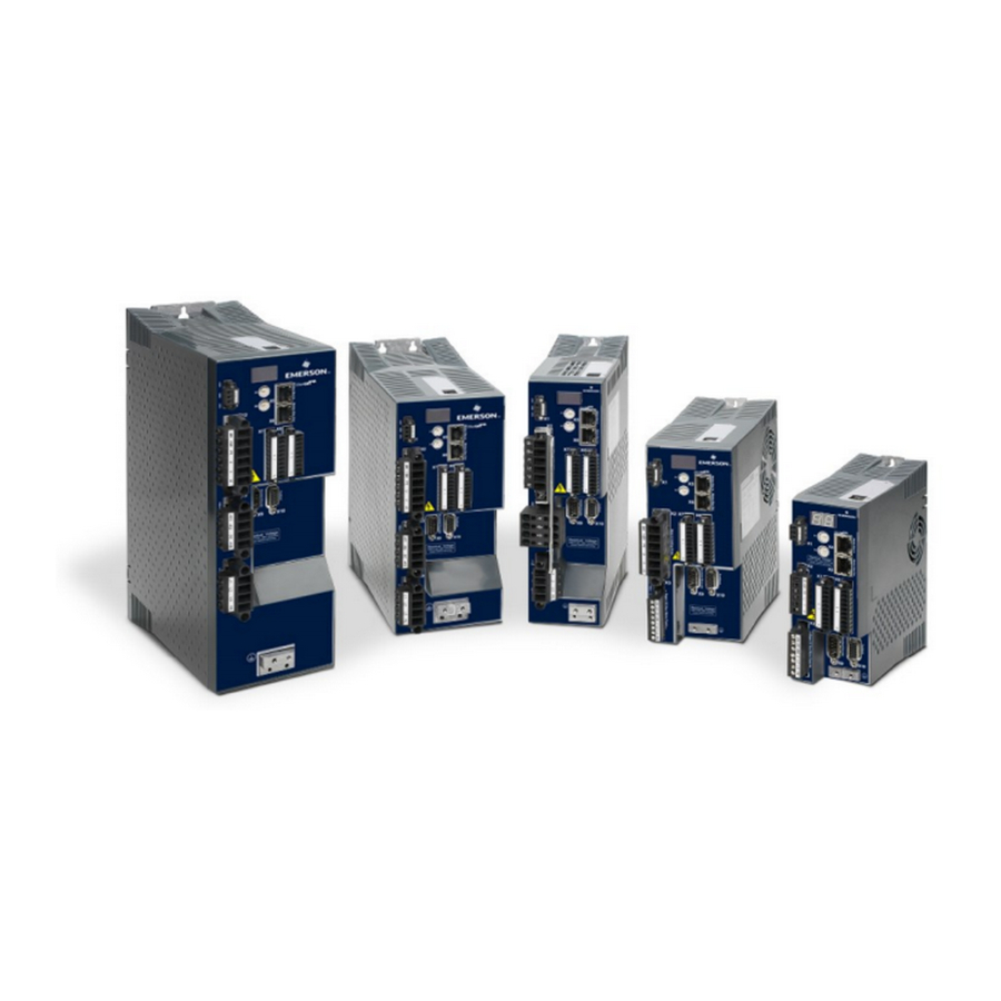
PACMotion™ PSD Installation and User Manual Section 4 GFK-3168A September 2020 Section 4 Technical Description and Data The PSD Family of Digital Drives Variant (short) Description Housing Connectivity Position Indexer drive adds the ability to command multiple motions, process I/O, make EtherCAT IC830DP Standard... -
Page 19: Auxiliary Supply Voltage 24V Dc
PACMotion™ PSD Installation and User Manual Section 4 GFK-3168A September 2020 4.1.4 Auxiliary supply voltage 24V DC From an external, safety approved 24 V ±10% power supply. 4.1.5 Operation and parameter setting Using the setup software Workbench for setup via TCP/IP 4.1.6 Full digital control •... -
Page 20: Ambient Conditions, Ventilation, And Mounting Position
PACMotion™ PSD Installation and User Manual Section 4 GFK-3168A September 2020 Ambient Conditions, Ventilation, and Mounting Position Storage / Transport (➜ # 19) / (➜ # 19) non UL/cUL regions: 0 to +40 °C under rated conditions Surrounding air tem- +40 to +55 °C with continuous current derating 4 % per Kelvin perature in operation UL/cUL regions: refer to UL approval (➜... -
Page 21: Inputs/Outputs
PACMotion™ PSD Installation and User Manual Section 4 GFK-3168A September 2020 Inputs/Outputs Interface Electrical Data ±12 VDC Common Mode Rejection Ratio: > 30 dB at 60 Hz resolution 16 bit and full Analog monotonic inputs update rate: 16 kHz nonlinearity < 0.1% of full scale offset drift max. 250µV/°C input impedance >... -
Page 22: Electrical Data Ic830Dpzzz07
PACMotion™ PSD Installation and User Manual Section 4 GFK-3168A September 2020 IC830D IC830D IC830D IC830D Electrical Data Units P00306 P00606 P01206 P02406 at 240 V Arms Peak output current Arms (for 5 s, ± 3%) Continuous output power @ rated input current at 1x120 V 312.5 1250... - Page 23 PACMotion™ PSD Installation and User Manual Section 4 GFK-3168A September 2020 IC830D IC830D IC830D IC830D Electrical data Units P00307 P00607 P01207 P02407 Permitted switch on/off frequency, mains Max. inrush current (@480V, 20°C) Rated DC bus link voltage (Bus Turn on Delay 3ph 1 340 to 680 sec) Continuous output current ( ±...
-
Page 24: Performance Data
PACMotion™ PSD Installation and User Manual Section 4 GFK-3168A September 2020 Performance Data 4.7.1 IC830DPzzz06 IC830D IC830D IC830D Performance Data Units P00606 P01206 P02406 Switching frequency of output stage Voltage rise speed dU/dt kV/µs Bandwidth of current controller 2.5 to 4 2 to 3 Bandwidth of velocity controller (scalable) 0 to 1000... -
Page 25: Grounding System
PACMotion™ PSD Installation and User Manual Section 4 GFK-3168A September 2020 Grounding System AGND Analog Ground DCOM7/8 common line for digital inputs on I/O connector X7, X8 24 V supply, STO input (up to IC830DP024), holding brake STO-GND STO-Enable inputs ( IC830DP048) internal digital ground, encoder emulation output, service channel 4.10 Fuses and breakers... -
Page 26: External 24 V Supply
PACMotion™ PSD Installation and User Manual Section 4 GFK-3168A September 2020 4.11 External 24 V supply Max. Example class J Example class J Ferraz Drive Model Bussmann Shawmut Ampere rating all PSD 8A (Time-Delay) LPJ8SP/DFJ8 AJT8 4.11.1 External regen resistor Ampere Ampere UL region... -
Page 27: Ic830Dpzzz06 Types (120V To 240V Mains Voltage Supply)
PACMotion™ PSD Installation and User Manual Section 4 GFK-3168A September 2020 4.12.2 IC830DPzzz06 types (120V to 240V Mains Voltage Supply) Connector Type Current Voltage Max. Cross Section 24V/STO X1 (03 Terminal Connector, 1.5 mm², 16 awg 160 V to 24A) 3 poles Motor X2 (3 to 6 Terminal Connector,... -
Page 28: Cable And Wire Requirements
PACMotion™ PSD Installation and User Manual Section 4 GFK-3168A September 2020 4.13 Cable and Wire Requirements 4.13.1 General For information on the chemical, mechanical, and electrical characteristics of the cables please refer to the accessories manual or contact customer support. To reach the maximum permitted cable length, you must use cable material with the following capacitance (phase to shield) requirements: Motor cable: less than 150 pF/m Resolver/Encoder cable: less than 120 pF/m... -
Page 29: Dynamic Braking
PACMotion™ PSD Installation and User Manual Section 4 GFK-3168A September 2020 4.14 Dynamic Braking Dynamic braking is a method to slow down a servo system by dissipating the mechanical energy driven by the motor back EMF. The PSD has a built in advanced dynamic braking mode which operates fully in hardware. -
Page 30: Technical Data For Ic830Dpzzz06
PACMotion™ PSD Installation and User Manual Section 4 GFK-3168A September 2020 takes place as described under 1. (above) for the drive that has the lowest switch-off threshold (resulting from tolerances). Note: Observe the regeneration time (some minutes) after full load with peak regen power. 4.14.3 Technical data for IC830DPzzz06 Technical data for the regen circuit depends on the drive type and the mains voltage. -
Page 31: Technical Data For Ic830Dpzzz07
PACMotion™ PSD Installation and User Manual Section 4 GFK-3168A September 2020 Type Rated data Units 120 V / 240 V Peak regen power, internal resistor (0.5s) External regen resistor Maximum continuous regen power, external resistor Peak regen power, external resistor (1s) 11.8 Absorption energy in capacitors (+/- 180 / 60... -
Page 32: Switch-On And Switch-Off Behavior
PACMotion™ PSD Installation and User Manual Section 4 GFK-3168A September 2020 Type Rated data Units 240 V 400 V / 480 V Continuous regen power, external resistor Peak regen power, external resistor 21.4 (1s) Absorption energy in capacitors (+/- 70 / 40 20%) DC Bus Capacitance µF... -
Page 33: Switch-On Behavior In Standard Operation
PACMotion™ PSD Installation and User Manual Section 4 GFK-3168A September 2020 4.14.6.2 Safety function STO With the functional safe function STO, the drive can be secured on standstill using its internal electronics so that even when power is being supplied, the drive shaft is protected against unintentional restart. -
Page 34: Switch-Off Behavior
PACMotion™ PSD Installation and User Manual Section 4 GFK-3168A September 2020 4.14.8 Switch-off behavior Note: The drive’s 24 V supply must remain constant. Hardware Enable input disables the power stage immediately. Configured Digital Inputs and fieldbus commands can be used to perform controlled stops. - Page 35 PACMotion™ PSD Installation and User Manual Section 4 GFK-3168A September 2020 Figure 3: Switch-Off Behavior using DRV.DIS Command If velocity drops below threshold CS.VTHRESH or timeout occurs brake is applied (➜ # 118). Technical Description and Data...
- Page 36 PACMotion™ PSD Installation and User Manual Section 4 GFK-3168A September 2020 4.14.8.2 Switch-off behavior using a digital input (controlled stop) This is a category 2 stop according to IEC 60204 (➜ # 52). A digital input can be configured to bring the motor to a controlled stop and then disable the drive and apply the holding brake.(if present).
-
Page 37: Switch-Off Behavior Using Hw Enable Input (Uncontrolled Stop)
PACMotion™ PSD Installation and User Manual Section 4 GFK-3168A September 2020 4.14.9 Switch-off behavior using HW Enable input (uncontrolled stop) This is a category 0 stop according to IEC 60204 (➜ # 52). Figure 5: Switch-Off Behavior use HW Enabled Input The hardware enable input disables the power stage immediately. - Page 38 PACMotion™ PSD Installation and User Manual Section 4 GFK-3168A September 2020 4.14.9.2 Switch-off behavior for faults that cause an immediate power stage disable Figure 6: Switch Off Behavior This is a category 0 stop according to IEC 60204 (➜ # 52). If velocity drops below threshold CS.VTHRESH or timeout occurs the motor holding brake is applied (➜...
- Page 39 PACMotion™ PSD Installation and User Manual Section 4 GFK-3168A September 2020 4.14.9.3 Switch-off behavior for faults that cause dynamic braking Figure 7: Switch-Off Behavior for Faults that Cause Dynamic Braking This is a category 0 stop according to IEC 60204 (➜ # 52). If velocity drops below threshold CS.VTHRESH or timeout occurs brake is applied (➜...
- Page 40 PACMotion™ PSD Installation and User Manual Section 4 GFK-3168A September 2020 4.14.9.4 Switch-off behavior for faults that cause a controlled stop Figure 8: Switch-off behavior for faults that cause a controlled stop This is a category 1 stop according to IEC 60204 (➜ # 52). If velocity drops below threshold CS.VTHRESH or timeout occurs brake is applied (➜...
-
Page 41: Stop / Emergency Stop / Emergency Off
PACMotion™ PSD Installation and User Manual Section 4 GFK-3168A September 2020 4.15 Stop / Emergency Stop / Emergency Off The control functions Stop, Emergency Stop and Emergency Off are defined by IEC 60204. Notes for safety aspects of these functions can be found in ISO 13849 and IEC 62061. Note: The parameter DRV.DISMODE must be set to 2 to implement the different stop categories. -
Page 42: Emergency Stop
PACMotion™ PSD Installation and User Manual Section 4 GFK-3168A September 2020 4.15.4 Emergency Stop The Emergency Stop function is used for the fastest possible shutdown of the machine in a dangerous situation. The Emergency Stop function is defined by IEC 60204. Principles of emergency stop devices and functional aspects are defined in ISO 13850. -
Page 43: Safety Characteristic Data
PACMotion™ PSD Installation and User Manual Section 4 GFK-3168A September 2020 4.16.2 Safety characteristic data The subsystems (PSD) are described with the following characteristic data: 4.16.2.1 IC830DP003 up to IC830DP024 Function Operation mode ISO 13849-1 IEC 62061 SFF [%] [1/h] [Years] single channel PL d, CAT 3... -
Page 44: Use As Directed
PACMotion™ PSD Installation and User Manual Section 4 GFK-3168A September 2020 CAUTION High electrical voltage! Risk of electrical shock! The STO function does not provide an electrical separation from the power output. If access to the motor power terminals is necessary, disconnect the drive from mains supply, consider the discharging time of the DC-Bus link. -
Page 45: Technical Data And Pinout
PACMotion™ PSD Installation and User Manual Section 4 GFK-3168A September 2020 4.16.6 Technical data and pinout 4.16.6.1 IC830DP003 up to IC830DP024 Reference ground is GND 24 V ±10%, 45 mA Galvanic isolation for 250 VDC Reaction time < 10 ms Figure 9: +24 GND STO Signal Description... -
Page 46: Enclosure, Wiring
PACMotion™ PSD Installation and User Manual Section 4 GFK-3168A September 2020 4.16.7 Enclosure, wiring Since the drive meets IP20, you must select an enclosure that permits safe operation of the drive. The enclosure must at least meet IP54 .Wiring remaining within the specified enclosure must meet the requirements of the standard IEC 60204-1 and ISO 13849-2 (Table D.4). - Page 47 PACMotion™ PSD Installation and User Manual Section 4 GFK-3168A September 2020 4.16.9.1 SIL2/PLd Single Channel Control With the single-channel control of the STO (SIL2/PLd) safety function, STO is switched by one output of a safety switching device (e.g. safety relay). Erroneous engaging will not be recognized. Therefore the output of the control must be supervised for possible malfunction.
- Page 48 PACMotion™ PSD Installation and User Manual Section 4 GFK-3168A September 2020 The sample application below shows door guarding and emergency stop, controlled by a safety controller to switch the STO-Enable input of an IC830DP003 to 024 device to SIL2, PLd. Note: Review the enclosure and wiring instructions (➜...
- Page 49 PACMotion™ PSD Installation and User Manual Section 4 GFK-3168A September 2020 4.16.9.4 Dual Channel control, SIL CL3 / PLe To achieve PLe / SIL CL3, the safe switching of the pulse inhibitor must be tested peri- odically by analyzing the feedback signal from a safety control: •...
-
Page 50: Shock-Hazard Protection
PACMotion™ PSD Installation and User Manual Section 4 GFK-3168A September 2020 Legend: FAULT: relay output, 1=ready to operate STO-ENABLE 1: digital input, 1st switch-off path STO-ENABLE 2: digital input, 2nd switch-off path STO-STATUS 1: digital output, switching state of 1st pulse inhibitor STO-STATUS 2: digital output, switching state of 2nd pulse inhibitor T1 …... -
Page 51: Residual Current Protective Device (Rcd)
Note: Recommendation: In order to protect against direct contact (with motor cables shorter than 5 m) Emerson recommends that each drive be protected individually using a 30 mA RCD which is sensitive to all currents. If you use a selective RCD, the more intelligent evaluation process will prevent spurious trip- ping of the RCD. -
Page 52: Mechanical Installation
PACMotion™ PSD Installation and User Manual Section 5 GFK-3168A September 2020 Section 5 Mechanical Installation Important Notes WARNING High EMC Voltage Level! Risk of electrical shock, if the servo amplifier (or the motor) is not properly EMC-grounded. Do not use painted (i.e. non-conductive) mounting plates. In unfavorable circumstances, use copper mesh tape between the earthing bolts and earth potential to deflect currents. -
Page 53: Guide To Mechanical Installation
PACMotion™ PSD Installation and User Manual Section 5 GFK-3168A September 2020 Guide to Mechanical Installation The following tools are required (at a minimum) to install the PSD; your specific installation may require additional tools: • M4 hexagon socket-cap screws (ISO 4762) 3 mm T-handle Allen key •... -
Page 54: Mechanical Drawings Standard Width
PACMotion™ PSD Installation and User Manual Section 5 GFK-3168A September 2020 Mechanical Drawings Standard Width 5.3.1 Control cabinet layout IC830DPzzz06, standard width Figure 14: Housing Clearance for Installation Material: M4 hexagon socket screws to ISO 4762, 3 mm T-handle Allen key Mechanical Installation... - Page 55 PACMotion™ PSD Installation and User Manual Section 5 GFK-3168A September 2020 Figure 15: Housing Clearance for Installation (cont'd) Mechanical Installation...
-
Page 56: Control Cabinet Layout Ic830Dpzzz07, Standard Width
PACMotion™ PSD Installation and User Manual Section 5 GFK-3168A September 2020 5.3.2 Control cabinet layout IC830DPzzz07, standard width Material: M4 hexagon socket screws to ISO 4762, 3 mm T-handle Allen key Figure 16: Control Cabinet Layout Schematic Mechanical Installation... - Page 57 PACMotion™ PSD Installation and User Manual Section 5 GFK-3168A September 2020 Mechanical Installation...
- Page 58 PACMotion™ PSD Installation and User Manual Section 5 GFK-3168A September 2020 Figure 17: Control Cabinet Layout Schematic (cont'd) Mechanical Installation...
-
Page 59: Important Notes
PACMotion™ PSD Installation and User Manual Section 5 GFK-3168A September 2020 Important Notes Note: Only professional staff who are qualified in electrical engineering are allowed to install the drive. Wires with color green with one or more yellow stripes must not be used other than for protective earth (PE) wiring. -
Page 60: Guide To Electrical Installation
Check the wiring against the wiring diagrams. Wiring The installation procedure is described as an example. A different procedure may be appropriate or necessary, depending on the application of the equipment. Emerson can provide training courses for this procedure upon request. DANGER High electrical voltage up to 900 V! There is a danger of serious personal injury or death by electrical shock or electrical arcing. - Page 61 PACMotion™ PSD Installation and User Manual Section 5 GFK-3168A September 2020 protective earth (PE) wiring. When installing or replacing cables, use only standardized components, which complies to the specifications in chapter 7.12 "Cable and Wire Requirements". Note: The ground symbol, which you will find in all the wiring diagrams, indicates that you must take care to provide an electrically conductive connection with the largest feasible surface area between the unit indicated and the mounting plate in the control cabinet.
-
Page 62: Components Of A Servosystem
PACMotion™ PSD Installation and User Manual Section 5 GFK-3168A September 2020 Components of a servosystem 5.7.1 With IC830DPzzz06 Note: Cables drawn bold are shielded. Electrical ground is drawn with dash-dotted lines. Optional devices are connected with dashed lines to the drive. The required accessories are described in the accessories manual. - Page 63 PACMotion™ PSD Installation and User Manual Section 5 GFK-3168A September 2020 5.7.1.1 With IC830DPzzz07 Note: Cables drawn bold are shielded. Electrical ground is drawn with dash-dotted lines. Optional devices are connected with dashed lines to the drive. The required accessories are described in the accessories manual.
-
Page 64: Connection Overview Of Ic830Dp Drive Connectors
PACMotion™ PSD Installation and User Manual Section 5 GFK-3168A September 2020 Connection Overview of IC830DP Drive Connectors Figure 20: IC830DP Drive Connectors Mechanical Installation... -
Page 65: Connector Assignment Ic830Dp00306, Ic830Dp00606
PACMotion™ PSD Installation and User Manual Section 5 GFK-3168A September 2020 5.8.1 Connector assignment IC830DP00306, IC830DP00606 Figure 21: Wiring Configuration for IC830DP00306, IC830DP00606 Mechanical Installation... -
Page 66: Connection Diagram Ic830Dp00306, Ic830Dp00606
PACMotion™ PSD Installation and User Manual Section 5 GFK-3168A September 2020 5.8.2 Connection diagram IC830DP00306, IC830DP00606 Figure 22: IC830DP00306 and -P00606 Mechanical Installation... - Page 67 PACMotion™ PSD Installation and User Manual Section 5 GFK-3168A September 2020 Connector assignment IC830DP01206. Figure 23: IC830DP01206 Mechanical Installation...
-
Page 68: Connector Assignment For Ic830Dp02406 And Ic830Dp00307 To 02407
PACMotion™ PSD Installation and User Manual Section 5 GFK-3168A September 2020 5.8.3 Connector Assignment for IC830DP02406 and IC830DP00307 to 02407 Figure 24: Connector Assignment for -P02406 and -P00307 Mechanical Installation... -
Page 69: Connection Diagram Ic830Dp02406 And Ic830Dp00307 To 02407
PACMotion™ PSD Installation and User Manual Section 5 GFK-3168A September 2020 5.8.4 Connection diagram IC830DP02406 and IC830DP00307 to 02407 Figure 25: Connection Diagram for -P02406, and -P00307 to -P02407 Mechanical Installation... - Page 70 PACMotion™ PSD Installation and User Manual Section 5 GFK-3168A September 2020 Mechanical Installation...
-
Page 71: Emi Noise Reduction
Ensure good ground connection. Connect from cabinet to proper earth ground. Ground leads should be the same gauge as the leads to main power or one gauge smaller. Use Emerson cables. Route power and control cables separately, Emerson recommends a distance of at least 200 mm to improve interference immunity. -
Page 72: Shielding With External Shielding Busbar
5.9.2 Shielding with external shielding busbar EMC filtering must be done externally by the user if necessary, which requires the use of shielded cables. Emerson recommends a star point shield connection, for example, with a shielding busbar. 5.9.2.1 Shielding Concept... - Page 73 The power cable shields (line in, motor cable, external regen resistor) can be routed to an additional busbar via shield clamps. Emerson recommends using shield clamps. A possible scenario for setting up a busbar for the above shield clamps is described below.
-
Page 74: Shielding Connection To The Drive
Use shield connection clamps (see accessories manual). These hook into the grounding plate and ensure optimum contact between the shield and the grounding plate. Emerson recommends using Phoenix Contact SK14 shield clamps with clamp range of 6-13mm. Figure 29: Shield Connection Lamps... - Page 75 PACMotion™ PSD Installation and User Manual Section 5 GFK-3168A September 2020 5.9.3.4 Motor connector X2 with shielding connection Figure 30: Motor Connector X2 with Shielding Connection Alternative connection for the motor power connection by mating connector with strain relief. Strip the external cable sheath to a length of approx. 120 mm, taking care not to damage the braided shield.
-
Page 76: Electrical Supply Connection
PACMotion™ PSD Installation and User Manual Section 5 GFK-3168A September 2020 5.10 Electrical Supply Connection 5.10.1 Connection to various mains supply networks IC830DPzzz06 (120V to 240V) Note: An isolating transformer is required for 400 to 480 V networks to get a maximum voltage of 240 V +10%. -
Page 77: Connection To Various Mains Supply Networks Ic830Dpzzz07 (240V To 480V)
PACMotion™ PSD Installation and User Manual Section 5 GFK-3168A September 2020 5.10.2 Connection to various mains supply networks IC830DPzzz07 (240V to 480V) Note: An isolating transformer is required for 120V networks to get a minimum voltage of 240 V +10%. Figure 32: Connection to various mains supply networks IC830DPzzz07 (240V to 480V) Mechanical Installation... -
Page 78: Auxiliary Supply (X1)
PACMotion™ PSD Installation and User Manual Section 5 GFK-3168A September 2020 5.10.3 24 V auxiliary supply (X1) The following diagram describes external 24 VDC power supply, electrically isolated, for example, via an isolating transformer. The required current rating depends on the use of motor brake card (➜... -
Page 79: Mains Supply Connection (X3, X4)
PACMotion™ PSD Installation and User Manual Section 5 GFK-3168A September 2020 5.10.4 Mains supply connection (X3, X4) Drives in the PSD series can be supplied as follows: • IC830DPzzz06: 1 or 3 phase industrial supply networks (not more than 200 kA symmetrical rated current at 120 V and 240 V). - Page 80 PACMotion™ PSD Installation and User Manual Section 5 GFK-3168A September 2020 5.10.4.1 Three phase connection • Fuses, all PSD types • 3-phase supply network, supply networks (➜ # 102). • Filtering for IC830DPzzz06 to be provided by the user. Fusing to be provided by the user (➜...
- Page 81 PACMotion™ PSD Installation and User Manual Section 5 GFK-3168A September 2020 5.10.4.2 Single/Dual phase connection (IC830DP00306 to IC830DP01206 only) +10% • Single-phase supply network (120 V to 240 V ) with neutral line or Two-phase -10% +10% supply network (120 V to 240 V ) without neutral line Supply networks(➜...
-
Page 82: Dc Bus Link (X3, X14)
PACMotion™ PSD Installation and User Manual Section 5 GFK-3168A September 2020 5.11 DC Bus link (X3, X14) The DC bus link can be connected in parallel so that the regen power is divided between all the drives that are connected to the same DC bus link circuit. Every drive must have its own power connection to mains voltage, even if the DC bus link is used. -
Page 83: Dc Bus Topology With Y Connectors (24 A Max.)
PACMotion™ PSD Installation and User Manual Section 5 GFK-3168A September 2020 Figure 36: Wiring to Drives 5.11.1 DC Bus topology with Y connectors (24 A max.) Without DC Bus fuses, other devices can become damaged or destroyed if, for example, a device fails due to an internal short circuit. -
Page 84: Dc Bus Topology With Busbar
PACMotion™ PSD Installation and User Manual Section 5 GFK-3168A September 2020 5.11.2 DC Bus topology with busbar This wiring does not require Y connectors. If a device fails due to a short-circuit, only its DC Bus fuses (➜ # 39). are tripped and the rest of the network continues uninterrupted. The solid busbars can conduct significantly larger currents, because the compensating current does not flow through the connector as above. - Page 85 PACMotion™ PSD Installation and User Manual Section 5 GFK-3168A September 2020 5.11.3.1 IC830DP003 to 024, regen connector X3 Ampere Ampere UL region CE Region example Drive Model rating@230V rating@480V example: (Siba): IC830DP003 to 012 10 A 40 A 110 V to 400 V: gRL(gS) FW-xxA14F IC830DP024...
-
Page 86: Motor Power Connection (X2)
The PSD drive is able to protect the connected motor from overloading, if the parameters are set correctly and the thermal protection sensor is connected and supervised. With Emerson motors the valid data are automatically set by the internal motor database. Refer to parameter MOTOR.RTYPE for supported thermal sensors. -
Page 87: Ic830Dp003 To 024, Power Connector X2
PACMotion™ PSD Installation and User Manual Section 5 GFK-3168A September 2020 5.12.1.1 Cable length ≤ 25 m Cable length >25 m Figure 41: Cable Length < 25 M Signal Description 1 -BR Motor holding brake (➜ # 118) 2 +BR Motor holding brake (➜... -
Page 88: Motor Brake Connection (X2, X15, X16)
PACMotion™ PSD Installation and User Manual Section 5 GFK-3168A September 2020 5.13 Motor Brake Connection (X2, X15, X16) A 24 V holding brake in the motor can be controlled directly by the drive. For proper function, check voltage drop, measure voltage at brake input and check brake function (on and off). WARNING No Functional Safety! Serious injury could result when the load is not properly blocked. -
Page 89: Ic830Dp003 To 024, Brake Connector X2
PACMotion™ PSD Installation and User Manual Section 5 GFK-3168A September 2020 5.13.1 IC830DP003 to 024, brake connector X2 Brake voltage supply via 24 V ±10% auxiliary voltage supply of the drive on X1. Maximum cur- rent depends on the drive type, see Technical Data (➜ # 36) or (➜ # 37). Figure 43: ALD-x003 to 024, brake connector X2 Mechanical Installation... -
Page 90: Functionality
PACMotion™ PSD Installation and User Manual Section 5 GFK-3168A September 2020 5.13.2 Functionality The brake function must be enabled through a parameter. The diagram below shows the timing and functional relationships between the controlled stop signal, speed, and braking force. All values can be adjusted with parameters;... -
Page 91: Feedback Connection (X10, X9, X7)
PACMotion™ PSD Installation and User Manual Section 5 GFK-3168A September 2020 5.14 Feedback Connection (X10, X9, X7) Every closed servo system normally requires at least one feedback device for sending actual values from the motor to the drive. Depending on the type of feedback device used, information will be fed back to the drive using digital or analog means. -
Page 92: Feedback Connector (X10)
PACMotion™ PSD Installation and User Manual Section 5 GFK-3168A September 2020 5.14.1 Feedback connector (X10) Figure 45: Feedback Connector (x10) BiSS B SFD3 Hiperface (analog) CLK+ CLK- SEN+ SEN+ SEN- SEN- COM+ DAT+ DAT+ COM- DAT- DAT- 8 to 9 V 8 to 9 V +5 V SIN+... -
Page 93: Sfd3
GFK-3168A September 2020 5.14.2 SFD3 The diagram below shows the connection of the two wire Emerson SFD3 feedback system. SFD3 can be used with the special Emerson cable. Maximum cable length is up to 25 m. Type FBTYPE Remarks SFD3 8 to 9 V from FW 1.11,with Emerson Cables only... -
Page 94: Led Display
PACMotion™ PSD Installation and User Manual Section 5 GFK-3168A September 2020 5.15 LED display The LED seven-segment display indicates the status of the drive after the 24 V supply is switched on. If the service connection to the PC or to the PAC doesn't work, then the LED display is the only way to get information. -
Page 95: Rotary Switches (S1, S2)
PACMotion™ PSD Installation and User Manual Section 5 GFK-3168A September 2020 5.16 Rotary Switches (S1, S2) Rotary switches can be used to select IP address or predefined functions for executing. PSD S1, S2 5.16.1 Rotary Switches S1 and S2 with PSD Drives Function Set while Remarks... -
Page 96: Push-Buttons (B1, B2, B3)
PACMotion™ PSD Installation and User Manual Section 5 GFK-3168A September 2020 5.17 Push-Buttons (B1, B2, B3) The push-buttons can be used to start predefined functions. Figure 47: B1, B2, B3 5.17.1 Push-Button B1 with PSD Drives Push Function Remarks button Display IP address Press short to display the IP address in the two digit display Switches Drive Type of... -
Page 97: Service Interface (X11)
PACMotion™ PSD Installation and User Manual Section 5 GFK-3168A September 2020 5.18 Service Interface (X11) Operating, position control, and motion-block parameters can be set up by using the setup software on an ordinary commercial PC (➜ # 189). PSD X11 Connect the service interface (X11) of the drive to an Ethernet interface on the PC directly or via a network hub/switch, while the supply to the equipment is switched off. -
Page 98: Possible Network Configurations
PACMotion™ PSD Installation and User Manual Section 5 GFK-3168A September 2020 5.18.3 Possible Network Configurations Figure 48: Network Configuration Example 5.18.4 Setting the IP Address IC830DP Figure 49: Setting IP Address The IP address can be flashed across the LED display if the B1 button is pressed. You can use the rotary switches to set the IP address of the PSD. - Page 99 PACMotion™ PSD Installation and User Manual Section 5 GFK-3168A September 2020 Rotary Switch Setting Drive IP Address DHCP/AutoIP address. The IP address of the drive is obtained from the DHCP server on your network. If no DHCP server is found the IP addresses is an AutoIP address (it is internally gen- erated following the AutoIP protocol and will be of the form 169.254.xx.xx).
-
Page 100: Ethercat Interface (X5/X6/Ethercat)
PACMotion™ PSD Installation and User Manual Section 5 GFK-3168A September 2020 5.18.4.5 Recovering Communications with a Drive on an Un-Reachable IP Address If IP.MODE has been set to 1 (using software defined static IP), the drive will boot up on an IP Address that may be unreachable with the host computer’s settings. -
Page 101: Pinout X5, X6, X11
PACMotion™ PSD Installation and User Manual Section 5 GFK-3168A September 2020 5.19.1 Pinout X5, X6, X11 Signal X5 Signal X6 Signal X11 Transmit + Receive+ Transmit + Transmit - Receive- Transmit - Receive+ Transmit + Receive+ n.c. n.c. n.c. Receive- Transmit - Receive- n.c. -
Page 102: Psd Setup
PACMotion™ PSD Installation and User Manual Section 6 GFK-3168A September 2020 Section 6 PSD Setup Important Notes Note: Only professional personnel with extensive knowledge in the fields of electrical engineering and drive technology are allowed to test and set up the drive. DANGER LETHAL VOLTAGE! There is a danger of serious personal injury or death by electrical shock. -
Page 103: Setup Of Psd Drives
This chapter describes the installation of the setup software PACMotion™ Workbench for PSD Drives. Figure 50: PACMotion Workbench Emerson offers training and familiarization courses on request. 6.2.2 Use as directed The setup software is intended to be used for altering and saving the operating parameters for the PSD series of drives. -
Page 104: Software Description
Non-plug and play Emerson motors are stored in PACMotion Workbench and can be loaded with one-click using the Motor screen in the PACMotion Workbench software. -
Page 105: Operating Systems
If Workbench is not installed on the user’s machine, a dialog window will appear with a link to Emerson’s Customer Center. From there, the user can locate and download a licensed copy of PACMotion Workbench. -
Page 106: Initial Drive Test Of The Psd
PACMotion™ PSD Installation and User Manual Section 6 GFK-3168A September 2020 6.2.6.2 Connection to the Ethernet interface of the PC Connect the interface cable to an Ethernet interface on your PC or to a Hub/Switch and to the service interface X11 of the PSD (➜ # 172). Figure 51: Connection to the Ethernet Interface of the PC 6.2.7 Initial Drive Test of the PSD... - Page 107 PACMotion™ PSD Installation and User Manual Section 6 GFK-3168A September 2020 6.2.7.2 Minimum wiring for drive test without load Note: This wiring diagram is for general illustration only and does not fulfill any requirements for EMC, safety, or functionality of your application. When connecting the PSD directly to a PC, static IP addressing (not 00) is recommended.
- Page 108 PACMotion™ PSD Installation and User Manual Section 6 GFK-3168A September 2020 Confirm that the link LEDs on the drive (green LED on the RJ45 connector) and on your PC are both illuminated. If both LEDs are illuminated, then you have a working electrical connection. Figure 53: LED While the PC is connecting, your status bar will show the following acquiring icon: Figure 54: Status Bar - Acquiring Connection...
- Page 109 PACMotion™ PSD Installation and User Manual Section 6 GFK-3168A September 2020 6.2.7.5 Set drive IP address in PACMotion Workbench If PACMotion Workbench does not automatically show your drive, then you can set the IP address manually in Workbench as follows: 1.
-
Page 110: Fault And Warning Messages
PACMotion™ PSD Installation and User Manual Section 6 GFK-3168A September 2020 Fault and Warning Messages 6.3.1 Fault and warning messages from the PSD PSD fault codes or warning codes are displayed constantly if present. Fault messages are coded with "F", warnings are coded with "n". When a fault occurs, the drive fault relay is opened, the output stage is switched off (motor loses all torque), or the load is dynamically braked. - Page 111 PACMotion™ PSD Installation and User Manual Section 6 GFK-3168A September 2020 Code Message/Warning F136 Firmware and FPGA versions are not compatible. n137 Homing and feedback mismatch. F138 Instability during autotune. F139 Target position overshot due to invalid motion task activation. n151 Not enough distance to move;...
- Page 112 PACMotion™ PSD Installation and User Manual Section 6 GFK-3168A September 2020 Code Message/Warning F406 BiSS multicycle fault. F407 BiSS sensor fault. F408 to F416 SFD feedback fault. F417 Broken wire in primary feedback. F418 Primary feedback power supply. F419 Encoder init procedure failed F421 SFD position sensor fault F423...
- Page 113 PACMotion™ PSD Installation and User Manual Section 6 GFK-3168A September 2020 Code Message/Warning F521, n521 Regen over power. F523 Bus over voltage FPGA F524, n524 Drive foldback. F525 Output over current. F526 Current sensor short circuit. F527 Iu current AD converter stuck. F528 Iv current AD converter stuck.
-
Page 114: Troubleshooting The Psd
PACMotion™ PSD Installation and User Manual Section 7 GFK-3168A September 2020 Section 7 Troubleshooting the PSD Drive problems occur for a variety of reasons, depending on the conditions in your installation. The causes of faults in multi-axis systems can be especially complex. If you cannot resolve a fault or other issue using the troubleshooting guidance presented below, customer support can give you further assistance. -
Page 116: General Contact Information
Note: If the product is purchased through an Authorized Channel Partner, please contact the seller directly for any support. Emerson reserves the right to modify or improve the designs or specifications of the products mentioned in this manual at any time without notice. Emerson does not assume responsibility for the selection, use or maintenance of any product.