
Related Manuals for Emerson Mini Maestro DCD60x3/6


Summary of Contents for Emerson Mini Maestro DCD60x3/6
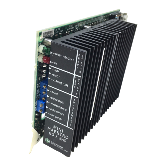
- Page 1 User Guide Mini Maestro Variable Speed Drive for Permanent-magnet DC Servo-motors Part Number: 0470-0009-05 Issue: 5 www.controltechniques.com...
- Page 2 Safety Information Persons supervising and performing the electrical installation or maintenance of a Drive and/or its external Option Unit must be suitably qualified and competent in these duties. They should be given the opportunity to study and if necessary to discuss this User Guide before work is started.
-
Page 3: Table Of Contents
Contents Data .................4 Mechanical Installation ..........6 Dimensions of the drive ................6 Mounting location ..................6 Choke (optional) ..................9 Electrical Installation ...........11 Connections ..................11 Grounding ....................13 External power supply ................13 Motor connections .................16 Signal connections ................17 Setting up the drive ............18 Adjusting the potentiometers ..............18 Mounted components ................19 Making adjustments to the drive ............20 Motor phasing ..................23... -
Page 4: Data
Data Analog speed reference input ±10V (33kΩ input impedance) Analog current reference input ±10V 22kΩ (TPRC) Enable signal Minimum 10V Maximum 30V 20kΩ input impedance ±25 µV / °C Error amplifier temperature drift Error amplifier offset Offset at 25°C ±100µV Tachogenerator feedback control range 1 to 5000 RPM Minimum tachogenerator signal at maximum speed... - Page 5 Output ratings Model Nominal current Peak current DCD60x3/6 1 to 3 A 6A for 2 sec. DCD60x7/14 2 to 7 A 14A for 2 sec. DCD60x10/20 3 to 10 A 20A for 2 sec. DCD60x14/28 5 to 14 A 28A for 2 sec. The peak current can be adjusted from 50% to 100% using the RIP resistor mounted on NOTE SK1.
-
Page 6: Mechanical Installation
Mechanical Installation Dimensions of the drive Figure 2-1 Overall dimensions of the drive Dimensions of the drive 100mm 3.937in 160mm 6.300in 0.315in 41mm 1.614in Mounting location Electric shock risk The heatsink on the drive is LIVE. Switch off the supply and wait at least 10 seconds before touching any part of the drive. - Page 7 If condensation is likely to occur when the drive is not in use, install an anti- condensation heater. This heater must be switched off when the drive is in use; automatic switching is recommended. Install the drive so that the heatsink fins are vertical for best flow of cooling air. Observe the requirements for ambient temperature if the drive is to be mounted directly above any heat generating equipment (such as another drive).
- Page 8 Figure 2-3 Dimensions of 3MB rack-mount installation kit Dimension 1.575 1.024 0.276 0.315 5.118 0.787 Mini Maestro User Guide www.controltechniques.com Issue Number: 5...
-
Page 9: Choke (Optional)
Figure 2-4 Dimensions of 2MH panel-mounting installation kit Dimension 2.598 0.591 0.315 5.197 0.197 Choke (optional) When a motor has an inductance less than 1mH, a choke must be connected between the motor and drive, and as close as possible to the drive. Refer to Figure 2-5 for dimensions of the choke. - Page 10 Figure 2-5 Dimensions of the L11 and L12 chokes Dimension 2.205 2.953 0.472 3.425 2.520 0.276 2.205 2.953 2.520 3.937 0.236 0.315 2.047 1.732 1.575 1.732 0.433 1.811 2.362 Hole diameter 0.157 0.157 Mini Maestro User Guide www.controltechniques.com Issue Number: 5...
-
Page 11: Electrical Installation
Electrical Installation Connections Installation kits Figure 3-1 Signal and power connections on the 3MB installation kit Figure 3-2 Signal and power connections on the 2MH installation kit Mini Maestro User Guide Issue Number: 5 www.controltechniques.com... - Page 12 Figure 3-3 Locations of the signal and power connections on the installation kits Edge connector of the drive When an installation kit is used, the functions of the connections on the edge connector do not need to be known. The connections are as follows: Pin number Function Signal common...
-
Page 13: Grounding
Grounding To avoid intermittent tripping of the drive, use a single ground point for the supply and signal circuits. A grounding bar of appropriate size can be used. This must be mounted on insulated supports as close as possible to the drive and connected to the chassis ground using cable of 10mm to 20mm . - Page 14 Figure 3-5 Single-phase and three-phase power supply circuits Transformer ratings Power rating Use the following equation: Pt = {(Paz x 1.7) + 80} x 1.73 ÷ √(n + 2) Where: Paz = (Vm1 x Cm1) + (Vm2 x Cm2) + ... Motor speed in radians per second (RPM ÷...
- Page 15 Reservoir capacitors Use the following equation to calculate the total required value of reservoir capacitance: C = (Pt ÷ V2) x 2000 µF The factor 2000 allows for regeneration current during braking. The factor can be reduced to 1000 when all of the following conditions apply: V2 = 24V to 45V Maximum motor speed = 1500 RPM Three-phase AC supply is used...
-
Page 16: Motor Connections
Motor connections Normally the motor should be connected directly to the connector on the installation kit. When any of the following conditions apply, a choke should be connected to each drive output as shown in Figure 3-6. • The motor inductance is less than 1mH •... -
Page 17: Signal Connections
Signal connections Signal cables and power cables must be segregated and wired through different NOTE trunking. Table 3.1 Signal connections common to both mounting kits Terminal Description Notes Analog signal proportional to the effective current in the motor. Output signal ± 8V at maximum current. NPN open-collector output 100mA, 47V. -
Page 18: Setting Up The Drive
Setting up the drive Set up the drive by adjusting potentiometers and replacing specific capacitors and fixed resistors. These components are fitted to socket SK1. If a drive is replaced, the socket can be transferred to the replacement drive in order to keep the settings. Adjusting the potentiometers Five potentiometers are labelled as follows: RAMP... -
Page 19: Mounted Components
Mounted components Figure 4-2 Locations of the mounted components on the drive The following resistors and capacitors are mounted on socket SK1: RIP resistor Reduces the peak current to the required value. RAI resistor Compensates for the voltage drop due to internal resistance of the motor. RIN resistor Reduces the nominal current to the required value. -
Page 20: Making Adjustments To The Drive
Making adjustments to the drive Zero speed offset ZERO REF potentiometer 1. Connect the non-inverting input of the speed reference signal to terminal 9 and the inverting input to terminal 10. 2. Set the speed reference signal for zero speed. 3. - Page 21 Adjusting the nominal current When the nominal current rating of the motor is less than the nominal current of the drive, it is possible to reduce the maximum value of current produced by the drive by fitting a RIN resistor. Refer to the following table: Model Nominal current 3 / 6...
- Page 22 The following equation can be used to calculate a value for the RAI resistor: motor × × × --------------------- - Ratot Where: Ip = Peak output current Ratot = Ra + Rsp1 + Rsp2 Ra = Armature resistance (Ω) Rsp = Brush resistance (Ω) An approximate value may be found experimentally using a RAI resistor value of 400kΩ...
-
Page 23: Motor Phasing
Motor phasing If the motor connections are not correct, the motor could rotate at a high speed in an unspecified direction. Before testing the motor, disconnect the motor from the machine and ensure the AC supply can be quickly disconnected from the drive. WARNING 1. - Page 24 Figure 4-3 Waveform resulting from insufficient proportional gain 11. The waveform could be as shown in Figure 4-3. In this case, the system has insufficient dynamic gain. Turn the PROPORTIONAL potentiometer clockwise to obtain a waveform without oscillation. 12. When a waveform without oscillation has been obtained, in most cases the response will have an overshoot as shown in Figure 4-4.
- Page 25 Figure 4-5 Ideal waveform Figure 4-6 Waveform resulting from excessive derivative gain It may be necessary to adjust repetitively the PROPORTIONAL and DERIVATIVE NOTE potentiometers. If the drive has instability problems after adjustment and when it is connected to a position controller, re-adjust the proportional and derivative gains.
- Page 26 The maximum acceptable amplitude for the current noise is 15% of the amplitude of the waveform. Figure 4-7 Block diagram of the drive Mini Maestro User Guide www.controltechniques.com Issue Number: 5...
-
Page 27: Diagnostics
Diagnostics Two LEDs and one digital output are available on the drive to give the following: Monitoring the status of the drive Diagnostics t protection LED indicators t protection indicator The I t LED is lit when I t exceeds the programmed value set by the RIN resistor. When the I t LED is lit, the drive is limited to the value of nominal current set by the RIN resistor. -
Page 28: Accessories
Accessories DCD60x3/6 DCD60x7/14 Single-phase AC power supply Code Description Part number Panel mount installation kit including fuses and 7500-0008 connecting cable Installation kit for 19 inch rack mounting including 7500-0009 screws and fuses 0.7mH, 8A inductor 4371-1108 Bridge rectifier 25A 400V single - phase bridge rectifier 10,000µF 75V electrolytic capacitor 1664-1000 DCD60x3/6... - Page 30 0470-0009-05...