
Related Manuals for Emerson Epsilon EP Drive 400518-01


Summary of Contents for Emerson Epsilon EP Drive 400518-01
-
Page 1: Epsilon Ep Drive
Epsilon EP Drive Installation Manual P/N 400518-01 Revision: A1 Date: December 15, 2006 © Control Techniques Americas LLC, 2006... - Page 3 Epsilon EP Drive Installation Manual Information furnished by Control Techniques Americas LLC (Control Techniques) is believed to be accurate and reliable. However, no responsibility is assumed by Control Techniques for its use. Control Techniques reserves the right to change the design or operation of the equipment described herein and any associated motion products without notice.
-
Page 4: Reference Materials
Control Techniques Americas LLC. Control Techniques Americas LLC a division of EMERSON Co. Control Techniques Americas LLC is not affiliated with Microsoft Corporation, owner of the Microsoft, Windows, and Windows NT trademarks. -
Page 5: Safety Information
Options and Safety Information Product Overview Installation Diagnostics Specification Accessories Safety Information Safety Precautions This product is intended for professional incorporation into a complete system by qualified persons. If you install the product incorrectly, it may present a safety hazard. The product and system may use high voltages and currents, carry a high level of stored electrical energy, or are used to control mechanical equipment that can cause injury. - Page 6 Options and Safety Information Product Overview Installation Diagnostics Specification Accessories “Caution” used without the safety alert symbol indicates a potentially hazardous situation that, if not avoided, may result in property damage. For the purpose of this manual and product, “Note” indicates essential information about the product or the respective part of the manual.
-
Page 7: Underwriters Laboratories Listed
Options and Safety Information Product Overview Installation Diagnostics Specification Accessories Underwriters Laboratories Listed LISTED 51Y8 IND. CONT. EQ. File E 58592 Sec.5 The Epsilon Digital Servo Drives are marked with the “UL Listed” label after passing a rigorous set of design and testing criteria developed by UL (UL508C). -
Page 8: Drive Overload Protection
Options and Safety Information Product Overview Installation Diagnostics Specification Accessories Drive Overload Protection Solid state motor overload protection is provided in each model at no more than 115% of rated FLA. This overload protection is based on maximum continuous output current capacity. It will allow up to 200 percent of drive FLA to be delivered for the amount of time determined by the following chart. -
Page 9: Ce Declaration Of Conformity
Options and Safety Information Product Overview Installation Diagnostics Specification Accessories CE Declaration of Conformity The Epsilon Digital Servo Drives are marked with the “Conformite Europeenne Mark” (CE mark) after passing a rigorous set of design and testing criteria. This label indicates that this product meets safety and noise immunity and emissions (EMC) standards when installed according to the installation guidelines and used within the product specifications. - Page 10 Options and Safety Information Product Overview Installation Diagnostics Specification Accessories viii...
-
Page 11: Table Of Contents
Table of Contents Reference Materials ............ii Safety Information Safety Precautions . - Page 12 Motor Feedback Wiring (J6) ..........23 Motor Brake Wiring.
-
Page 13: Product Overview
Options and Safety Information Product Overview Installation Diagnostics Specification Accessories Product Overview Epsilon EP Drive The Epsilon EP drive is a stand-alone, fully digital brushless servo drive designed and built to reliably provide high performance and flexibility without sacrificing ease of use. The use of State-Space algorithms make tuning very simple and forgiving. - Page 14 Options and Safety Information Product Overview Installation Diagnostics Specification Accessories Epsilon EP drives are rated at 240 Vac input voltage and can operate with an input voltage from 20 to 264 Vac. The EP drives are available in three current ratings. Drive Model Continuous Power Rating Continuous Current...
-
Page 15: Installation
Options and Safety Information Product Overview Installation Diagnostics Specification Accessories Installation Installation of the Epsilon EP drive is completed by following a simple step-by-step process. The Epsilon EP installation begins by mounting the drive to a metal mounting panel. Next, the high power connections are made to the drive, then the low power connections are made. -
Page 16: Electrostatic Discharge (Esd) Protection
Options and Safety Information Product Overview Installation Diagnostics Specification Accessories Bringing components into direct contact cannot always be achieved. In these situations a conductor must be relied upon to provide a low impedance path between components. Remember a flat braided wire has lower impedance than a round wire of a large gauge rating. -
Page 17: Panel Layout
Options and Safety Information Product Overview Installation Diagnostics Specification Accessories • You should consider future troubleshooting and repair when installing all wiring. All wiring should be either color coded and/or tagged with industrial wire tabs. • As a general rule, the minimum cable bend radius is ten times the cable outer diameter. •... -
Page 18: Cable To Enclosure Shielding
Options and Safety Information Product Overview Installation Diagnostics Specification Accessories Cable to Enclosure Shielding Shielded motor, feedback, serial communications and external encoder cables were used for compliance testing and are necessary to meet the EMC requirements. Each cable shield was grounded at the enclosure wall by the type of grommet described earlier and shown in the following figure. -
Page 19: Ac Line Filters
Options and Safety Information Product Overview Installation Diagnostics Specification Accessories AC Line Filters The AC line filters are necessary to comply with EMC emission and immunity standards. The drive was tested with the filters presented in the table below and recommended by Control Techniques. Epsilon EP Schaffner Part # Control Techniques Part #... - Page 20 Options and Safety Information Product Overview Installation Diagnostics Specification Accessories The following table applies to the "A" dimension as shown in figure 4 below for the base and indexing drives. Drive Model Dimension "A" Minimum Panel Width -B or -I only inches [mm] inches [mm] EP202...
- Page 21 Options and Safety Information Product Overview Installation Diagnostics Specification Accessories The following table applies to the "A" dimension as shown in figure 5 for the programming drives. Dimension "A" Minimum Panel Width Drive Model inches [mm] inches [mm] EP202-Pxx-xxxx 2.69 [68.3] 3.45 [88] EP204-Pxx-xxxx 2.69 [68.3]...
-
Page 22: Step 3: High Power Connections
Options and Safety Information Product Overview Installation Diagnostics Specification Accessories Step 3: High Power Connections System Grounding To insure a safe and quiet electrical installation, good system grounding is imperative. The figure below is an overview of the recommended system grounding. For more information on achieving an electrically quiet installation refer to “Step 1: Basic Installation Guidelines”... -
Page 23: Ac Power Requirements
Options and Safety Information Product Overview Installation Diagnostics Specification Accessories Fixed Protective Earth (PE) connections are mandatory for human safety and proper operation. These connections must not be fused or interrupted by any means. Failure to follow proper PE wiring can cause death or serious injury. -
Page 24: Ac Supplies Requiring Transformers
Options and Safety Information Product Overview Installation Diagnostics Specification Accessories DISTRIBUTION PANEL SECONDARY 230 Vac To Fusing and Drive Terminals No Fuse (Protective Earth) EARTH GROUND NOTE: For single phase drives using lines L1 & L2 or L1 & L3, only one fuse is required on the high leg (L2 or L3). - Page 25 Options and Safety Information Product Overview Installation Diagnostics Specification Accessories DISTRIBUTION PANEL 3 Ø Isolation Transformer To Fusing and Drive Terminals EARTH (Protective Earth) GROUND Figure 10: Three-Phase WYE (ungrounded) Distribution to a Three-Phase Delta/WYE Isolation Transformer DISTRIBUTION PANEL 3 Ø Isolation Transformer To Fusing and Drive Terminals No Fuse...
-
Page 26: Transformer Sizing
Options and Safety Information Product Overview Installation Diagnostics Specification Accessories DISTRIBUTION PANEL 3 Ø Isolation Step Down Transformer To Fusing and > 140 Vac Drive Terminals EARTH (Protective Earth) GROUND Figure 12: Grounded WYE Distribution >140 Vac Phase to Neutral. Recommend Using Step Down Transformer so Line to Line is 240 Vac or less. - Page 27 Options and Safety Information Product Overview Installation Diagnostics Specification Accessories When multiple drives are connected to a single isolation transformer, add the suggested KVA ratings of the drives that would be operating simultaneously together for transformer sizing. Drive/Motor Combination Suggested KVA Rating EP202/NT-207 EP202/NT-212 EP204/NT-207...
-
Page 28: Line Fusing And Wire Size
Options and Safety Information Product Overview Installation Diagnostics Specification Accessories Line Fusing and Wire Size You must incorporate over current protection for the incoming AC power with the rating shown here. UL approval for operation with the circuit breakers identified in the table below is pending. At present, fuses shown must be used for installation to meet UL. -
Page 29: Ac Input Power Connections
Options and Safety Information Product Overview Installation Diagnostics Specification Accessories AC Input Power Connections Power must be "Off" for a minimum of 6 minutes for the Epsilon EP206 drive and 3 minutes for the Epsilon EP202/204 drives before unplugging the power connection. This will ensure the bus voltage has bled down to a safe level (below 50 Vdc). -
Page 30: External Shunt Electrical Installation
Options and Safety Information Product Overview Installation Diagnostics Specification Accessories Both supply conductors must be fused except one that is grounded. The fuse must be rated for at least the voltage applied. The current rating of the fuse should match the rated output current of the drive. A slow-blow fuse should be used if high peak loads are expected. -
Page 31: Motor Power Wiring
Options and Safety Information Product Overview Installation Diagnostics Specification Accessories Figure 15:Shunt Resistor Connections showing SM-Heatsink DBR-1 Kit Do Not make any shunt resistor connections to B-. Shunt connections are at main voltage potential. Components connected must be rated for the voltage and selected for safety. -
Page 32: Front View
Options and Safety Information Product Overview Installation Diagnostics Specification Accessories Wire crimp ferrules are recommanded: For ground lead use - Pheonix Contact p/n AI-TWIN 2X1, 5-8Bk/32 00 82 3 American Electrical/DigiKey 1381015/288-1130-ND For motor leads use - Pheonix Contact p/n AI 1,5-8 RD/32 01 13 6 or ALTEC p/n H1.5/14 2204.0 Pk/100 Front View NT or MG Motor... - Page 33 Options and Safety Information Product Overview Installation Diagnostics Specification Accessories XV Motor Power Wiring The XV 40 mm to 80 mm motors are equipped with up to three connectors, one for stator connections, one for encoder connections and one for the brake (if so equipped). Stator connections from the drive to the motor are made using the XTMDS cable, the motor end of the cable has an Amp "Mate-N-Lok"®...
-
Page 34: Step 4: Low Power Connections
Options and Safety Information Product Overview Installation Diagnostics Specification Accessories Step 4: Low Power Connections DC Logic Power Supply Wiring The Epsilon drive requires a user supplied logic power supply, 24 Vdc ±10%, to power the internal logic of the drive. Use the table below to determine the current requirements of the application. -
Page 35: Motor Feedback Wiring (J6)
Options and Safety Information Product Overview Installation Diagnostics Specification Accessories to the logic supply are PELV, the wiring need not be isolated from direct contact within a zone of equipotential bonding, normally an enclosure or set of enclosures bonded together. Otherwise, logic wiring and circuits must be isolated from direct contact by basic insulation for 300 V system voltage. - Page 36 Options and Safety Information Product Overview Installation Diagnostics Specification Accessories XV 40-80 mm Motor Motor Feedback Cable XVM 40mm, 60mm, Epsilon Model # XEFTS-XXX and 80mm Motor Drive +5 V Blue Orange Green 220 Ohm Brown Black Yellow +5 V White/Brown Brown/White White/Gray...
-
Page 37: Motor Brake Wiring
Options and Safety Information Product Overview Installation Diagnostics Specification Accessories Motor Brake Wiring The NT and MG motors equipped with brakes have a three-pin MS style connector. The brake power cable (model CBMS-XXX) has an MS style connector on the motor end and three wire leads on the drive end (see the following wiring diagrams). -
Page 38: Input/Output And Drive Enable Wiring
Options and Safety Information Product Overview Installation Diagnostics Specification Accessories XV 40mm-80mm Motor Black - Customer supplied drive Internal enable contact Output #3 to Motor Drive Enable 2 Amp Fuse I/O Supply Red + 1 Amp Relay: Fuse XTBMS-xxx Cable I/O Common Model# BRM-1 EP204-I00-0000... - Page 39 Options and Safety Information Product Overview Installation Diagnostics Specification Accessories Inputs are ON with +10 Vdc to +30 Vdc applied and OFF when less than +1.5 Vdc or 0.2 mA is applied. Input current at 24 Vdc is 4.8 mA and input resistance is about 4.8k ohms. Maximum load on each output channel is 150 mA with 3.5 Vdc max voltage drop from I/O supply + to output.
- Page 40 Options and Safety Information Product Overview Installation Diagnostics Specification Accessories J3 Connector Function Pin# Input Line 1 Input Line 3 Input Line 5 Input Line 7 Input Line 9 Input Line 11 Output Line 1 Output Line 3 Output Line 5 Enable Input Line 2 Input Line 4...
- Page 41 Options and Safety Information Product Overview Installation Diagnostics Specification Accessories Analog/Sync Output Connector (J5) All command, diagnostic, and sync signals are available using the 15-pin Analog/Sync Output connector. If interfacing the drive using field wiring, the optional standard terminal interface board (STI-SNCOA) may be used. It provides convenient connections using screw terminal strips.
- Page 42 Options and Safety Information Product Overview Installation Diagnostics Specification Accessories Function Pin Numbers Electrical Characteristics Encoder Out 1, 2, 3, 9, 10, 11 Differential line driver output (RS 422) Diagnostic Output 7, 15 ± 10 Vdc 10 mA maximum analog diagnostic, ref. to pins 6 and 14 Diagnostic Output Common 6, 14 0.0 V, 10 ohms away from PE.
- Page 43 Options and Safety Information Product Overview Installation Diagnostics Specification Accessories Sync Input Connector (J10) Sync Input signals are connected to the drive using the 9-pin Sync Input connector. If interfacing the drive using field wiring, the optional standard terminal interface board (STI-SNCI) may be used. 1 2 3 4 5 6 7 8 Figure 31:...
-
Page 44: Analog Command Wiring
Options and Safety Information Product Overview Installation Diagnostics Specification Accessories Analog Command Wiring (Internal) 10 Ohm Logic Common Analog/Sync Output Connector (J5) Single Point Panel Ground External CW Rotation Controller + Command = CW With positive direction = CW Controller Logic Common Single Point Panel Ground Figure 33:... - Page 45 Options and Safety Information Product Overview Installation Diagnostics Specification Accessories Note: If the external controller does not have an internal terminating resistor R1, R2 and R3 must be mounted within 3 ft [1 m] of the external controller. A 120 ohm resistor is recommended for high frequency encoders (over 250 kHz) or cables longer than 25 feet.
- Page 46 Options and Safety Information Product Overview Installation Diagnostics Specification Accessories Pulse Mode Wiring, Differential Inputs 500 ns Minimum Shield connected 500 ns Minimum to connector shell Drive Sync Input Connector 250 ns Minimum (J10) Motion occurs 10 Ohm on rising edge (A) Pulse A A/ B B/ (B) Direction...
- Page 47 Options and Safety Information Product Overview Installation Diagnostics Specification Accessories Pulse Mode Wiring, Single Ended Inputs 1 µs Minimum 1 µs Minimum 500 ns Minimum Motion occurs Pulse on falling edge Drive Analog/Sync Output Shield connected (J5) to connector shell logic common Pulse...
- Page 48 Options and Safety Information Product Overview Installation Diagnostics Specification Accessories 1 µs Minimum 1 µs Minimum 500 ns Minimum Motion occurs CW Pulse on falling edge Drive Analog/Sync Output Connector Shield connected (J5) to connector shell logic common CCW Pulse Pulse Direction Sinking...
-
Page 49: Communications
Options and Safety Information Product Overview Installation Diagnostics Specification Accessories Communications Communications with the drive is provided through the RJ45 connectors located on the front of the drive. The two RJ45 connectors are identical and are used to provide a way to daisy chain two or more drives together using the DDC-RJ45 cable, see Figure 44. - Page 50 Options and Safety Information Product Overview Installation Diagnostics Specification Accessories Figure 43: Epsilon EP Serial Communication Connector DDC-RJ45 cable Figure 44: 2 Epsilon Drives Daisy Chained Together When connecting the serial port of your PC to the serial port of the drive, verify that your PC’s ground is the same as the drive PE ground.
-
Page 51: Ethernet Port
Options and Safety Information Product Overview Installation Diagnostics Specification Accessories Modbus Communications The drive’s serial communication protocol is Modbus RTU slave with a 32 bit data extension. The Modbus protocol is available on most operator interface panels and PLC’s. Serial Communications Specifications Max baud rate 19.2k Start bit... - Page 52 Options and Safety Information Product Overview Installation Diagnostics Specification Accessories...
-
Page 53: Diagnostics And Troubleshooting
Options and Safety Information Product Overview Installation Diagnostics Specification Accessories Diagnostics and Troubleshooting Diagnostic Display Status Codes The diagnostic display on the front of the drive shows drive status and fault codes. When a fault condition occurs, the drive will display the fault code, overriding the status code. The decimal point is “On” when the drive is enabled and the Stop input is not active. -
Page 54: Fault Codes
Options and Safety Information Product Overview Installation Diagnostics Specification Accessories Display Indication Status Description Summation Summation mode operation. RMS Foldback Motor torque is limited to 80 percent. Drive output current is limited to 80 percent of the Stall Foldback drive’s stall current. Ready to Run Drive enabled, no Stop input. - Page 55 Options and Safety Information Product Overview Installation Diagnostics Specification Accessories The +/- Travel Limit faults are automatically cleared when the fault condition is removed. The table below lists all the fault codes in priority order from highest to lowest. This means that if two faults are active, only the higher priority fault will be displayed.
-
Page 56: Fault Descriptions
Options and Safety Information Product Overview Installation Diagnostics Specification Accessories Display Fault Action to Reset Bridge Disabled Allow Motor to cool down, Motor Overtemp Reset Button or Input Line RMS Shunt Power Reset Button or Input Line Overspeed Reset Button or Input Line Following Error Reset Button or Input Line (Pulse mode only) -
Page 57: Power Module
Options and Safety Information Product Overview Installation Diagnostics Specification Accessories NVM Invalid At power-up the drive tests the integrity of the non-volatile memory. This fault is generated if the contents of the non- volatile memory are invalid. Invalid Configuration This fault will occur if the digital board in the drive does not match the power board settings. It is only useful during manufacturing. - Page 58 Options and Safety Information Product Overview Installation Diagnostics Specification Accessories Encoder Hardware If any pair of complementary encoder lines (A, B, Z) are in the same state, an encoder line fault is generated. Also, can be generated if all three commutation channels (U, V, W) are 0 or 1, an illegal state. The most likely cause is a missing or bad encoder connection.
-
Page 59: Diagnostic Analog Output Test Points
Options and Safety Information Product Overview Installation Diagnostics Specification Accessories Trajectory Fault #2 This fault occurs when using the "Using Capture.#" option in a user program. If the capture has never been triggered, or the capture data has gone "stale", the drive will not be able to process motion properly. Program Fault This fault indicates a problem was encountered in a user program. -
Page 60: Resetting Faults
Options and Safety Information Product Overview Installation Diagnostics Specification Accessories Figure 45: Active Drive Faults Detected Dialog Box Resetting Faults Some drive faults are automatically reset when the fault condition is cleared. Other faults require drive logic power to be cycled or the drive to be “rebooted”. If you wish to continue working in the PowerTools Pro software without resetting the fault, click the Ignore Fault button. -
Page 61: Options And Accessories
Options and Safety Information Product Overview Installation Diagnostics Specification Accessories Options and Accessories Epsilon EP Drive Options Drive Brake Relay, BRM-1 External Shunt Resistor, SM-Heatsink DBR1 Motor Power Cable, XTMDS-xxx Motor Brake Cable, XTBMS-xxx XV Motors ESA HMI to Drive, ESA-SP-485-xxx Motor Power Cable, XCMDS-xxx or XCMDBS-XXX... -
Page 62: Sti-24Io
Options and Safety Information Product Overview Installation Diagnostics Specification Accessories STI-24IO The STI-24IO interface board allows access to all digital input and output signals. The STI-24IO mounts directly to the digital I/O connector (J3) on the front of the EP drive. See figure 47 below. Do not allow ESD directly to terminals. -
Page 63: Sti-Sncoa
Options and Safety Information Product Overview Installation Diagnostics Specification Accessories STI-SNCOA The STI-SNCOA interface board allows access to the analog/sync signals. The STI-SNCOA plugs directly into the J5 connector on the bottom of the drive. The numbers printed on the connector label correlate to the screw terminal numbers. -
Page 64: Sti-Snci
Options and Safety Information Product Overview Installation Diagnostics Specification Accessories STI-SNCI The STI-SNCI interface board allows access to the sync input connections on the EP drive. The STI-SNCI plugs directly into the J10 connector on the bottom of the drive. The numbers printed on the connector label correlate to the screw terminal numbers. -
Page 65: Sti-Enc
Options and Safety Information Product Overview Installation Diagnostics Specification Accessories STI-ENC The STI-ENC interface board allows the user access to the encoder feedback connector (J6) on the EP drive. The STI-ENC plugs directly in J6 on the bottom of the drive. The numbers printed on the connector label correlate to the screw terminal numbers. - Page 66 Options and Safety Information Product Overview Installation Diagnostics Specification Accessories...
-
Page 67: Specifications
Options and Safety Information Product Overview Installation Diagnostics Specification Accessories Specifications Epsilon EP Specifications Epsilon EP Series 20 Vac-264 Vac, 1 Ø, 47-63 Hz (240 Vac for rated performance) Power Requirements Type TN (Grounded) Installation Category III SCCR 10,000 Symmetrical RMS Amps (Short Circuit Current Rating) Model Continuous Power... - Page 68 Options and Safety Information Product Overview Installation Diagnostics Specification Accessories Epsilon EP Series Analog command: ±10 Vdc 14 bit, 100 kOhm impedance, differential Absolute Maximum Input Voltage Input: +/- 14 Vdc to ground or differential, including drive enable Control Inputs Digital Inputs: 5 on the EP-B and 16 on the EP-I and EP-P including the drive enable input, 10 Vdc - 30 Vdc, 4.8 kohm impedance;...
- Page 69 Options and Safety Information Product Overview Installation Diagnostics Specification Accessories Epsilon EP Series Low DC bus (can be disabled) High DC bus Power Stage fault Logic power Encoder state Encoder line break Drive overtemperature Fault Detection Capability Motor overtemperature Overspeed Travel limit (+) Travel limit (-) Following error...
-
Page 70: Epsilon Ep Drive Dimensions
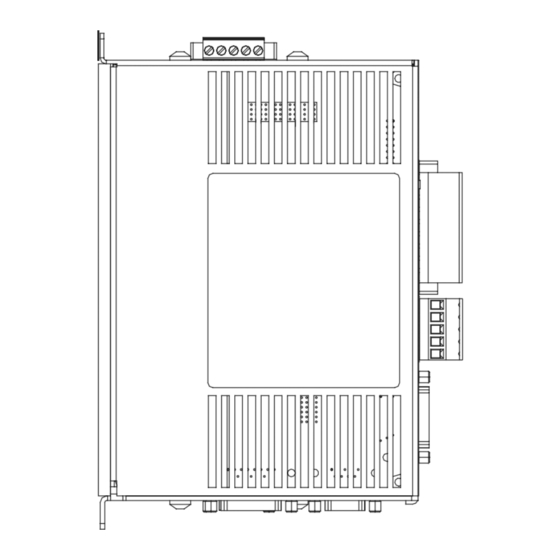
Options and Safety Information Product Overview Installation Diagnostics Specification Accessories Epsilon EP Drive Dimensions The following table applies to A* and B* as shown in the figure below. Dimension A* Dimension B* Drive Model (shown in inches/mm) (shown in inches/mm) EP202-B,-I,-IDN 2.11 [53.59] 0.45 [11.4]... -
Page 71: Cable Diagrams
Options and Safety Information Product Overview Installation Diagnostics Specification Accessories Cable Diagrams EIO26 Cable 1.530 PIN 1 0.770 LT. BLU ENABLE RED/WHT INPUT LINE 1 LT. BLU/WHT INPUT LINE 2 ORG/WHT INPUT LINE 3 LT. GRN/WHT INPUT LINE 4 GRN/WHT INPUT LINE 5 YEL/GRY INPUT LINE 6... -
Page 72: Xv Motor Cables
Options and Safety Information Product Overview Installation Diagnostics Specification Accessories XV Motor Cables XTMDS-XXX Cable PIN 1 BRAID SHIELD FORM WIRE GRN/YEL PE/GND REAR VIEW OF CONNECTOR... - Page 73 Options and Safety Information Product Overview Installation Diagnostics Specification Accessories XCMDS-XXX BRAID SHIELD FORM WIRE GRN/YEL PE/GND (20 AWG) BLU/WHT (20 AWG) Drain Wire SOLDER SIDE Socket Specifications...
- Page 74 Options and Safety Information Product Overview Installation Diagnostics Specification Accessories XCMDBS-XXX FORM WIRE BRAID SHIELD GRN/YEL PE/GND (20 AWG) BRK+ BLU/WHT (20 AWG) BRK - Drain Wire SOLDER SIDE Socket...
- Page 75 Options and Safety Information Product Overview Installation Diagnostics Specification Accessories XTBMS-XXX PIN 1 +24V DRAIN WIRE REAR VIEW OF CONNECTOR Specifications...
- Page 76 Options and Safety Information Product Overview Installation Diagnostics Specification Accessories XEFTS-XXX Cable Pin 1 PIN 1 Inner Drain Wire Inner Drain Wire Inner Drain Wire WHT/BRN BRN/WHT WHT/GRY GRY/WHT RED/ORG ORG/RED RED/BLU (18 ga.) +5 VDC +5 VDC BLU/RED (18 ga.) COMMON Inner Drain Wire RED/GRN...
- Page 77 Options and Safety Information Product Overview Installation Diagnostics Specification Accessories XEFCS-XXX Cable Pin 1 Inner Drain Wire Inner Drain Wire Inner Drain Wire WHT/BRN BRN/WHT WHT/GRY GRY/WHT RED/ORG ORG/RED RED/BLU (18 ga.) +5 VDC +5 VDC BLU/RED (18 ga.) COMMON Inner Drain Wire RED/GRN MOTOR TEMP...
-
Page 78: Nt And Mg Motor Cables
Options and Safety Information Product Overview Installation Diagnostics Specification Accessories NT and MG Motor Cables CMDS-XXX Cable 1 1/2" MAX. 3 3/4" MAX. GRN/YEL SHELL SOLDER SIDE CMMS-XXX Cable 1 1/2" MAX. GRN/YEL SHELL SOLDER SIDE... - Page 79 Options and Safety Information Product Overview Installation Diagnostics Specification Accessories CBMS-XXX Cable DRAIN WIRE SOLDER SIDE Socket Specifications...
- Page 80 Options and Safety Information Product Overview Installation Diagnostics Specification Accessories EFCS-XXX Cable Pin 1 Inner Drain Wire Inner Drain Wire WHT/BRN Inner Drain Wire BRN/WHT WHT/GRY GRY/WHT RED/ORG ORG/RED RED/BLU +5 VDC +5 VDC BLU/RED COMMON RED/GRN Inner Drain Wire MOTOR OVERTEMP MOTOR TEMP GRN/RED...
-
Page 81: Sync Cables
Options and Safety Information Product Overview Installation Diagnostics Specification Accessories Sync Cables SNCDD-915-XXX Pin 1 Pin 1 Drain Wire 12 11 SOLDER SIDE SOLDER SIDE SNCFLOA-XXX Pin 1 Blunt end ENCODER OUT A ENCODER OUT A ENCODER OUT B ENCODER OUT B ENCODER OUT Z ENCODER OUT Z WHT/BRN... - Page 82 Options and Safety Information Product Overview Installation Diagnostics Specification Accessories SNCMD-815-XXX Pin 1 +5 VDC DRAIN WIRE 12 11 CONNECTOR END VIEW SOLDER SIDE SNCFLI-XXX Pin 1 Blunt end Drain Wire SOLDER SIDE...
- Page 83 Options and Safety Information Product Overview Installation Diagnostics Specification Accessories SNCMD-89-XXX Pin 1 Pin removed Drain Wire Completely remove pin 4 SOLDER SIDE CONNECTOR END VIEW Specifications...
-
Page 84: Communications Cables
Options and Safety Information Product Overview Installation Diagnostics Specification Accessories Communications Cables ESA-SP-485-XXX Drain Wire WHT/GRN SIGNAL GND SIGNAL GND WHT/BLU TXRX+ TXRX+ TXRX- TXRX- WHT/ORG WHT/BRN 470 Ω 13 12 25 24 470 Ω 220 Ω SOLDER SIDE PIN 1 Pin 1 ETH-PATCH-XXX WHITE... -
Page 85: Index
Index AC Line Filter Installation Notes, 7 EIO26-XXX Cable, 59 AC Line Filters, 6 Electromagnetic Compatibility, 3 AC Supplies NOT Requiring Transformers, Encoder Output Signal Wiring, 32 Environmental Considerations, 4 AC Supplies Requiring Transformers, 12 Epsilon EP Drive Options, 49 Achieving Low Impedance Connections, 3 Epsilon EP Specifications, 55 Analog Command Wiring, 32... - Page 86 Motor Brake Wiring, 25 Underwriters Laboratories Recognition, v Motor Feedback Wiring, 23 Motor Power Wiring, 19 Viewing Active Drive Faults, 48 Options and Accessories, 49 Wire Size, 16 Wiring Notes, 4 Product Overview, 1 Pulse Mode Wiring, 34 Rebooting the Drive, 48 Resetting Faults, 48 Safety Information, iii Safety of Machinery, iii...
- Page 88 For more information about Control Techniques “Motion Made Easy” products and services, call (800) 893-2321 or contact our website at www.emersonct.com. Control Techniques Americas LLC Division of EMERSON Co. 12005 Technology Drive Eden Prairie, Minnesota 55344-3620 U.S.A. Customer Service...