
Related Manuals for Allen-Bradley 1734-IB8S


Summary of Contents for Allen-Bradley 1734-IB8S
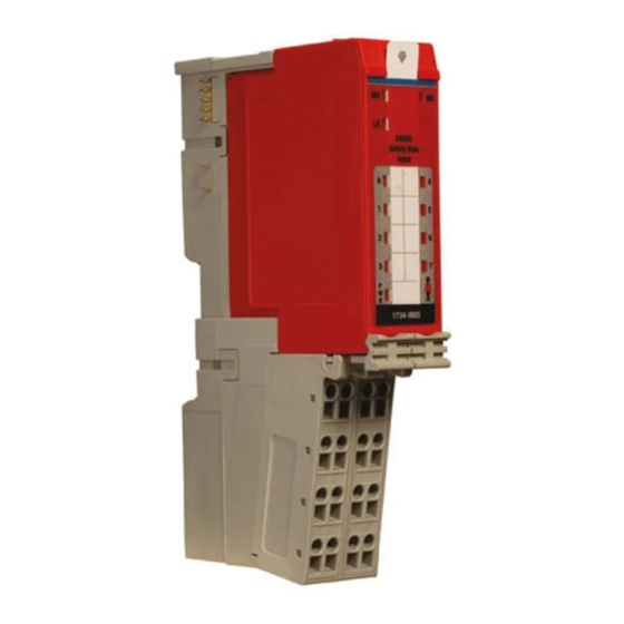
- Page 1 User Manual Original Instructions Point Guard I/O Safety Modules Catalog Numbers 1734-IB8S, 1734-OB8S, 1734-IE4S, 1734-OBV2S...
- Page 2 Important User Information Read this document and the documents listed in the additional resources section about installation, configuration, and operation of this equipment before you install, configure, operate, or maintain this product. Users are required to familiarize themselves with installation and wiring instructions in addition to requirements of all applicable codes, laws, and standards.
- Page 3 Rockwell Automation Publication 1734-UM013N-EN-P - September 2017...
- Page 4 Rockwell Automation Publication 1734-UM013N-EN-P - September 2017...
- Page 5 Safety Inputs (1734-IB8S) ........
- Page 6 Table of Contents Muting Lamp Operation (1734-IB8S) ......44 I/O Status Data ..........45 Digital I/O Status Data .
- Page 7 Table of Contents Add the Safety Analog Input Module ..... . . 98 Configure the Safety Analog Input Channel Operation ..101 Configure the Safety Analog Inputs .
- Page 8 1734-IE4S Safety Analog Input Status ......168 1734-IB8S Safety Input Status....... . . 168 1734-OB8S Safety Output Status.
- Page 9 Table of Contents Output Assemblies ......... . . 216 Analog Input Assemblies.
- Page 10 Table of Contents Notes: Rockwell Automation Publication 1734-UM013N-EN-P - September 2017...
- Page 11 Summary of Changes This manual contains new and updated information as indicated in the following table. Topic Page Updated important statement on grounding. Rockwell Automation Publication 1734-UM013N-EN-P - September 2017...
- Page 12 Preface Notes: Rockwell Automation Publication 1734-UM013N-EN-P - September 2017...
- Page 13 Preface Thoroughly read and understand this manual before installing and operating a system that uses POINT Guard I/O™ modules. Always observe the following guidelines when using a module. In this manual, we use safety administrator to mean a person who is qualified, authorized, and responsible to secure safety in the design, installation, operation, maintenance, and disposal of the ‘machine’...
-
Page 14: Additional Resources
Provides declarations of conformity, certificates, and other certification details. certification/overview.page You can view or download publications at http://www.rockwellautomation.com/literature/. To order paper copies of technical documentation, contact your local Allen-Bradley distributor or Rockwell Automation sales representative. Rockwell Automation Publication 1734-UM013N-EN-P - September 2017... - Page 15 Chapter POINT Guard I/O Overview Topic Page Understand Suitability for Use Safety Precautions POINT Guard I/O Modules in CIP Safety Systems Safety Application Requirements Use the POINT Guard I/O™ safety modules in the POINT I/O™ platform to distribute safety I/O on a safety-control network that meets the requirements up to and including SIL CL3, and PLe, Cat.
- Page 16 You are responsible for confirming compliance with the applicable standards for the entire system. Table 1 - Requirements for Controlling Devices Device Requirement Allen-Bradley® Bulletin Safety Components Emergency stop switches Use approved devices with direct opening mechanisms that comply with IEC/EN Bulletin 800F, 800T 60947-5-1.
-
Page 17: Safety Precautions
POINT Guard I/O Overview Chapter 1 Safety Precautions Observe these precautions for proper use of POINT Guard I/O modules. ATTENTION: As serious injury can occur due to loss of required safety function, follow these safety precautions. • Never use test outputs as safety outputs. Test outputs are not safety outputs. •... -
Page 18: Securing The System
Chapter 1 POINT Guard I/O Overview Securing the System To secure access to the [device] by authorized users only, consider these options: • Password protect the source and execution of the control program • Remove the key from the controller •... -
Page 19: Point Guard I/O Modules In Cip Safety Systems
In addition to I/O state data, the modules include status data for monitoring I/O faults within each circuit. A password can help protect the configuration information of the modules. 1734-IB8S Digital Input Module Features • Safety digital inputs – Safety devices, such as Emergency Stop Push Button, gate switches, and safety light curtains, can be connected. -
Page 20: Ob8S Safety Digital Output Module Features
Chapter 1 POINT Guard I/O Overview • Test outputs (digital input modules only) – Separate test outputs are provided for short circuit detection of a safety input (or inputs). – Power (24V) can be supplied to devices, such as safety sensors. –... -
Page 21: Programming Requirements
Version DeviceNet Software (EtherNet/IP Network) Version (DeviceNet Network) 1734-IB8S, 1734-OB8S 1734-OBV2S 1734-IE4S (1) This version or later. (2) If you are using digital POINT Guard I/O modules with the analog POINT Guard I/O module, you must update the Add-on Profiles to version 2.02.004 or later for the modules to be compatible with version 18 or later of RSLogix 5000 software and the Studio... -
Page 22: Safety Application Requirements
Chapter 1 POINT Guard I/O Overview Figure 1 - POINT Guard I/O Modules in EtherNet/IP Safety Architecture GuardLogix Controller Stratix™ Switch CompactBlock™ Guard I/O™ POINT Guard I/O and POINT I/O Safety Communication Standard Communication Figure 2 - POINT Guard I/O Modules in DeviceNet Safety Architectures GuardLogix Controller SmartGuard... - Page 23 POINT Guard I/O Overview Chapter 1 For safety system requirements, including information on the safety network number (SNN), verifying the safety signature, functional verification test intervals, system reaction time, and PFD/PFH calculations, refer to the following publications. For safety requirements in: See: GuardLogix controller systems GuardLogix 5570 Controller Systems Safety Reference...
- Page 24 Chapter 1 POINT Guard I/O Overview Notes: Rockwell Automation Publication 1734-UM013N-EN-P - September 2017...
- Page 25 Page Safe States Safety Inputs (1734-IB8S) Safety Analog Inputs (1734-IE4S) Safety Outputs (1734-OB8S and 1734-OBV2S) Muting Lamp Operation (1734-IB8S) I/O Status Data Safe States POINT Guard Digital I/O Modules ATTENTION: • The safe state of the outputs is defined as the off state.
-
Page 26: Point Guard I/O Analog Input Module
(OFF). – If a dual-channel discrepancy fault occurs, the dual-channel inputs continue to report actual input signals. Safety Inputs (1734-IB8S) Safety inputs are used to monitor safety input devices. Using a Test Output with a Safety Input A test output can be used in combination with a safety input for short circuit, cross-channel, and open-circuit fault detection. - Page 27 Chapter 2 Figure 5 - Test Pulse in a Cycle For the 1734-IB8S module, the pulse width (X) is typically 525 μs; the pulse period (Y) is typically 144 ms. When the external input contact is closed, a test pulse is output from the test output terminal to diagnose the field wiring and input circuitry.
-
Page 28: Single-Channel Mode
Chapter 2 Safety Inputs, Safety Outputs and Safety Data Single-channel Mode If an error is detected, safety input data and safety input status turn off. Figure 7 - Normal Operation and Fault Detection (Not to Scale) Normal Operation Test Output 0 External Device Input Terminal 0 Safety... -
Page 29: Dual-Channel Mode And Discrepancy Time
Safety Inputs, Safety Outputs and Safety Data Chapter 2 Dual-channel Mode and Discrepancy Time To support dual-channel safety devices, the consistency between signals on two channels can be evaluated. Either equivalent or complementary can be selected. If the length of a discrepancy between the channels exceeds the configured discrepancy time (0…65,530 ms in increments of 10 ms), the safety input data and the individual-safety input status turn off for both channels. -
Page 30: Dual-Channel, Equivalent
Chapter 2 Safety Inputs, Safety Outputs and Safety Data Dual-channel, Equivalent In Equivalent mode, both inputs of a pair must be in the same (equivalent) state. When a transition occurs in one channel of the pair before the transition of the second channel of the pair, a discrepancy occurs. -
Page 31: Dual-Channels, Complementary
Safety Inputs, Safety Outputs and Safety Data Chapter 2 Dual-channels, Complementary In Complementary mode, the inputs of a pair must be in the opposite (complementary) state. When a transition occurs in one channel of the pair before the transition of the second channel of the pair, a discrepancy occurs. If the second channel transitions to the appropriate state before the discrepancy time elapsing, the inputs are considered complementary. -
Page 32: Safety Input Fault Recovery
Chapter 2 Safety Inputs, Safety Outputs and Safety Data Safety Input Fault Recovery If an error is detected, the safety input data remains in the OFF state. Follow this procedure to activate the safety input data again. 1. Remove the cause of the error. 2. -
Page 33: Safety Analog Inputs (1734-Ie4S)
Safety Inputs, Safety Outputs and Safety Data Chapter 2 Safety Analog Inputs Safety analog-input channels can be configured for current, voltage, or tachometer inputs, and for input type: single-channel or dual-channel equivalent. (1734-IE4S) If you are using the module with a GuardLogix® controller, set the inputs of the IMPORTANT module to Single (default). -
Page 34: Digital Input Filter
Chapter 2 Safety Inputs, Safety Outputs and Safety Data Digital Input Filter A single-pole, anti-aliasing filter of 10 Hz is followed by a four-pole digital filter. Choose from the following available corner frequencies. • 1 Hz • 5 Hz • 10 Hz •... -
Page 35: Channel Offset
Safety Inputs, Safety Outputs and Safety Data Chapter 2 When a channel is configured for module sensor power, a sensor power diagnostic is executed on that channel at powerup. The diagnostic is used to make sure that the sensors are not drawing over- or under-current and that channel-to-channel shorts are not present. -
Page 36: Using A Single-Channel Sensor
Chapter 2 Safety Inputs, Safety Outputs and Safety Data You can configure a tolerance range, called a deadband, to work with process alarms. This deadband lets the process alarm status bit remain set, despite the alarm condition disappearing, as long as the data remains within the deadband of the process alarm. -
Page 37: Dual-Channel Equivalent Mode
Safety Inputs, Safety Outputs and Safety Data Chapter 2 Dual-channel Equivalent Mode If you are using the module with a GuardLogix controller, set the inputs of the IMPORTANT module to Single (default). Do not use the dual-channel mode of the module as this functionality is provided by the GuardLogix safety application instructions. -
Page 38: Tachometer Mode
Chapter 2 Safety Inputs, Safety Outputs and Safety Data Tachometer Mode In Tachometer mode, the module measures digital pulses between 0 and 24V DC and converts them into a frequency or pulses per second. Therefore, you can use 24V DC proximity sensors or 5V DC encoders, for example. The Tachometer function does not sense direction, so using a differential encoder does not yield direction data. -
Page 39: Safety Outputs
Safety Inputs, Safety Outputs and Safety Data Chapter 2 Figure 16 - Pulse Trains Falling Edge Rising Edge Ideal Pulse Train Falling and rising edges are well-defined. Pull-down resistor helps define falling edges. Falling edges are not well-defined. Pull-up resistor helps define rising edges. Rising edges are not well-defined. -
Page 40: Safety Outputs
Chapter 2 Safety Inputs, Safety Outputs and Safety Data Overfrequency Bit Operation When the frequency exceeds 1 kHz, the module reports a data value of 1 kHz, sets the Overfrequency status bit to 0, and latches it. While the Overfrequency bit is set to 0, you must use an alternate method to monitor the frequency of the system because the value reported by the module is latched at 1 kHz. -
Page 41: Safety Output With Test Pulse
Safety Inputs, Safety Outputs and Safety Data Chapter 2 Safety Outputs Read this section for information about safety outputs. (1734-OB8S and 1734-OBV2S) Safety Output with Test Pulse When the safety output is on, the safety output can be configured to pulse test the safety output channel. -
Page 42: Dual-Channel Mode
Chapter 2 Safety Inputs, Safety Outputs and Safety Data Dual-channel Mode When the data of both channels is in the on state, and neither channel has a fault, the outputs are turned on. The status is normal. If a fault is detected on one channel, the safety output data and individual safety output status turn off for both channels. -
Page 43: Single-Channel Mode, 1734-Ob8S Only
Safety Inputs, Safety Outputs and Safety Data Chapter 2 Single-channel Mode, 1734-OB8S Only When the data of the channel is in the on state, and does not have a fault, the output is turned on. The status is normal. If a fault is detected on the channel, the safety output data and individual safety output status turn off. -
Page 44: Muting Lamp Operation (1734-Ib8S)
T1 and T3. Keep these points in mind as well: • When power is applied to the 1734-IB8S module, and T1 or T3 remains commanded off, the muting status defaults to on. -
Page 45: I/O Status Data
Safety Inputs, Safety Outputs and Safety Data Chapter 2 This bit operation is designed to help prevent erroneous muting instruction faults from the GuardLogix controller. This bit status is not always the true indication of a burned-out lamp. Before checking the state of the corresponding muting status, be sure that the IMPORTANT test output is commanded on. -
Page 46: Digital I/O Status Data
Chapter 2 Safety Inputs, Safety Outputs and Safety Data Digital I/O Status Data The following data is monitored: • Individual Point Input Status • Combined Input Status • Individual Point Output Status • Combined Output Status • Individual Test Output Status •... - Page 47 Chapter Guidelines for Placing Power Supplies and Modules in a System Topic Page Choosing a Power Supply Power Supply Examples Placing Series A Digital and Analog Modules Choosing a Power Supply The POINTBus™ backplane includes a 5V communication bus and field power bus that get their power from a communication adapter or expansion power supplies.
- Page 48 Chapter 3 Guidelines for Placing Power Supplies and Modules in a System Follow the safety precautions that are listed in Chapter 1 and the wiring guidelines that are described in Chapter 4 before connecting a power supply to the system. To choose which types of power supplies meet your requirements, you must consider the power consumption requirements for the 5V and 24V bus when designing a POINTBus backplane.
-
Page 49: Example 1: Isolating Field Power Segments
• POINT Guard I/O does not require separate field-bus power usage, that is, separate power supplies for the 1734-IB8S, 1734-OB8S, 1734-OBV2S, or 1734-IE4S modules. This step is optional. • POINT Guard I/O does not require separate POINTBus (communication) power-supply usage, which separates it from any other POINT I/O modules, except when additional POINTBus power is required. -
Page 50: Example 2: Point Guard I/O Used With Ac I/O Modules
Chapter 3 Guidelines for Placing Power Supplies and Modules in a System Example 2: POINT Guard I/O Used with AC I/O Modules This power supply example uses 1734-EP24DC and 1734-EPAC expansion power supplies to illustrate mixing standard POINT I/O and safety POINT Guard I/O modules, while creating a separate power group for AC I/O modules. -
Page 51: Placing Series A Digital And Analog Modules
Guidelines for Placing Power Supplies and Modules in a System Chapter 3 Placing Series A Digital and Always install modules in accordance with their specified operating temperature ratings, as listed in Appendix, and provide a minimum of 5.08 cm (2 in.) Analog Modules clearance above the modules. -
Page 52: Placing Series B Digital Modules
Chapter 3 Guidelines for Placing Power Supplies and Modules in a System Placing Series B Digital Always install modules in accordance with their specified operating temperature ratings, as listed in Appendix C, and provide a minimum of 5.08 cm (2 in.) Modules clearance above the modules. - Page 53 Chapter Install the Module Topic Page Precautions Install the Mounting Base Connect the Module to the Mounting Base Connect the Removable Terminal Block Remove a Mounting Base Wire Modules Connection Details Wiring Examples Figure 25 - POINT Guard I/O™ Modules Slide-in Writable Label Module Locking Mechanism...
-
Page 54: Install The Module Precautions
Chapter 4 Install the Module Precautions Follow these precautions for use. ATTENTION: This equipment is certified for use only within the surrounding air temperature range of -20…+55 °C (-4…+131 °F). The equipment must not be used outside of this range. ATTENTION: Use only a soft dry anti-static cloth to wipe down equipment. -
Page 55: European Hazardous Location Approval
Install the Module Chapter 4 European Hazardous Location Approval The following applies to products marked II3G: • Are Equipment Group II, Equipment Category 3, and comply with the Essential Health and Safety Requirements relating to the design and construction of such equipment given in Annex II to Directive 2014/34/ EU. -
Page 56: North American Hazardous Location Approval
Chapter 4 Install the Module North American Hazardous Location Approval The following information applies when operating this Informations sur l’utilisation de cet équipement en equipment in hazardous locations. environnements dangereux. Products marked “CL I, DIV 2, GP A, B, C, D” are suitable for use in Les produits marqués “CL I, DIV 2, GP A, B, C, D”... -
Page 57: Prevent Electrostatic Discharge
Install the Module Chapter 4 Prevent Electrostatic Discharge ATTENTION: This equipment is sensitive to electrostatic discharge, which can cause internal damage and affect normal operation. Follow these guidelines when you handle this equipment: • Touch a grounded object to discharge potential static. •... - Page 58 Chapter 4 Install the Module Follow these steps to install the mounting base. 1. Position the mounting base as shown in the illustration below step 2. 2. Slide the mounting base down, allowing the interlocking side pieces to engage the adjacent module, power supply, or adapter. Slide the mounting base to let the interlocking side pieces engage the adjacent module or adapter.
-
Page 59: Connect The Module To The Mounting Base
Monitor which mounting base gets installed on the left and right of each module. Cat. No. Key 1 (Left) Key 2 (Right) 1734-IB8S 1734-OB8S 1734-OBV2S 1734-IE4S Mounting Base Assembly Keyswitch Locking Mechanism 2. -
Page 60: Connect The Removable Terminal Block
Chapter 4 Install the Module Connect the Removable Terminal Block If a removable terminal block (RTB) is supplied with your mounting base assembly, you must remove it by pulling up on the RTB handle. This action lets you remove and replace the base as necessary without removing any of the wiring. WARNING: When you connect or disconnect the removable terminal block (RTB) with field-side power applied, an electric arc can occur. -
Page 61: Remove A Mounting Base
Install the Module Chapter 4 Remove a Mounting Base To remove a mounting base, you must remove any installed module and the module that is installed in the base to the right. If the mounting base has a removable terminal base (RTB), unlatch the RTB handle on the I/O module and pull on the handle to remove the RTB. - Page 62 Chapter 4 Install the Module ATTENTION: Wire the POINT Guard I/O modules properly so that 24V DC line does not touch the safety outputs accidentally or unintentionally. Do not connect loads beyond the rated value to safety outputs. Wire conductors correctly and verify operation of the module before placing the system into operation.
-
Page 63: Terminal Layout
28, and Figure 29 on page 64 show the field wiring connections for the POINT Guard I/O modules. Figure 26 - 1734-IB8S Field Connections 1734-TOP and 1734-TB Bases Shown Where: T0 = Test Output 0 T1M = Test Output 1 with Muting... - Page 64 Chapter 4 Install the Module Figure 29 - 1734-IE4S Field Connections 1734-TOP3 Base Shown Where: V0…V3 = Voltage inputs 0…3 I0…I3 = Current inputs 0…3 COM = Supply Common S0…S3 = Sensor power terminals Rockwell Automation Publication 1734-UM013N-EN-P - September 2017...
-
Page 65: Connection Details
Install the Module Chapter 4 Connection Details See the tables that show input device connection methods and their safety categories. Connected Device Test Pulse from Connection Schematic Diagram Safety Test Output Category Push Button Connect the push button between 24V DC and I0. - Page 66 Chapter 4 Install the Module Connected Device Test Pulse from Connection Schematic Diagram Safety Test Output Category Light Curtain Connect the OSSD1 and OSSD2 to I0 and 3 or 4 based on I1, respectively. Connect the 24V power light curtain supply commons.
-
Page 67: Wiring Examples
When used in combination with the programs in a safety controller, this wiring is safety Category 4 (emergency stop button) and safety Category 3 (gate monitoring switch). Figure 30 - 1734-IB8S POINT Guard I/O Module Wiring (dual-channel contacts) 1734-TB, 1734-TOP, 1734- TOP3 Bases Shown Only with the 1734-TOP3 base. -
Page 68: Single-Channel Safety Contactor
Chapter 4 Install the Module Single-channel Safety Contactor This example shows wiring and controller configuration when using a 1734-OB8S digital POINT Guard I/O module with one safety contactor. When used in combination with the programs of the safety controller, this circuit configuration is safety Category 2. -
Page 69: Dual-Channel Safety Contactors
Install the Module Chapter 4 Dual-channel Safety Contactors This example shows wiring and controller configuration when using a 1734-OB8S digital POINT Guard I/O module with redundant safety contactors. When used in combination with the programs of the safety controller, this circuit configuration is safety Category 4. -
Page 70: Bipolar Safety Outputs
Bipolar Safety Outputs These examples show how to wire a 1734-OBV2S output module with an input module to meet PLe and PLd safety requirements. Figure 33 - 1734-OBV2S Dual Safety Output Wiring - PLe 1734-OBV2S 1734-IB8S Controller Parameter Name Configuration Setting Configuration... -
Page 71: Safety Analog Input Wiring
Install the Module Chapter 4 Safety Analog Input Wiring The following sections contain important guidelines for wiring safety analog inputs and wiring examples for the 1734-IE4S module. Guidelines for Wiring Safety Analog Inputs Follow these guidelines when wiring your safety analog inputs. For eight terminal connections, either the 1734-TOP or 1734-TB terminal base can be used. - Page 72 Chapter 4 Install the Module Safety Analog Input Wiring Examples Figure 35 - 2-wire Current (4…20 mA) Sensor (SIL2 or SIL 3) 1734-TB Terminal Bases Signal (I) SIL2 or SIL 3 2-wire +24V Sensor Cable Shield Figure 36 - 3-wire Voltage or Tachometer Sensor (SIL 2) 1734-TB Terminal Bases Signal (V) SIL 2...
- Page 73 Install the Module Chapter 4 Figure 37 - 3-wire Current Sensor (SIL 2) 1734-TB Terminal Bases Signal (I) SIL 2 3-wire Signal Return Sensor +24V Cable Shield For 0…20 mA analog current-output sensors, the signal levels for operation for the application must be outside the signal level when the signal is not present, for example, when the wire is broken.
- Page 74 Chapter 4 Install the Module Figure 39 - 4-wire Current Sensor (SIL 2) 1734-TOP3 Terminal Bases Signal (I) SIL 2 Signal Return 4-wire Sensor +24V Common Cable Shield Signal Return and Common are at the same potential. Figure 40 - 2-wire Current (4…20 mA) Sensor (SIL 3) 1734-TB Terminal Bases Signal (I) SIL 2...
- Page 75 Install the Module Chapter 4 Figure 41 - 3-wire Voltage or Tachometer Sensor (SIL 3) 1734-TB Terminal Bases Signal (V) SIL 2 Signal Return 3-wire Sensor +24V Signal (V) SIL 2 Signal Return 3-wire Sensor +24V Cable Shield Cable Shield This wiring configuration can also be used for SIL 2 redundant Tachometer mode.
- Page 76 Chapter 4 Install the Module Figure 43 - 4-wire Voltage or Tachometer Sensor (SIL 3) 1734-TOP3 Terminal Bases Signal (V) SIL 2 Signal Return 4-wire Sensor +24V Common Signal (V) SIL 2 Signal Return 4-wire Sensor +24V Common Cable Shield Cable Shield This wiring configuration may also be used for SIL 2 redundant Tachometer mode.
- Page 77 Install the Module Chapter 4 In the following two examples, the negative terminal of the sensor power supply and that of the 1734 terminal base COMMON must be at the same potential. Use of an external power supply limits diagnostics and increases susceptibility to noise.
- Page 78 Chapter 4 Install the Module Figure 47 - Safety Analog Input Wiring for Sinking Tachometer Sensor 1734-TOP3 Terminal Bases Sinking Sensor (NPN-type) Metal Oxide or Carbon Composition Resistor Pull-up Transistor Pull-down Edge-to-edge Time Measured Here 1734-IE4S with Trigger = Falling Edge Figure 48 - Safety Analog Input Wiring for Sourcing Tachometer Sensor Sourcing Sensor 1734-TOP3 Terminal Bases...
- Page 79 Chapter Configure the Module in a GuardLogix Controller System Topic Page Set up the Module Add and Configure the Ethernet Bridge Add and Configure the 1734 Ethernet Adapter Add and Configure Safety Digital Input Modules Add and Configure Safety Digital Output Modules Add and Configure Safety Analog Input Modules Values and States of Tags Configure Safety Connections...
-
Page 80: Guardlogix Controller System Add And Configure The Ethernet Bridge
1. From the I/O Configuration tree, right-click 1756 Backplane, 1756-Axx, and choose New Module. 2. In the Select Modules dialog box, check Communication and Allen-Bradley®. 3. Choose an Ethernet module from the list and click Create. In this example, we chose the 1756-EN2T bridge. These module revisions support CIP Safety. -
Page 81: Add And Configure The 1734 Ethernet Adapter
1. Right-click the Ethernet connection and choose New Module. Ethernet Adapter 2. On the Select Module dialog box, check Communication and Allen-Bradley. 3. Choose an Ethernet adapter from the list and click Create. Rockwell Automation Publication 1734-UM013N-EN-P - September 2017... - Page 82 Chapter 5 Configure the Module in a GuardLogix Controller System 4. Specify the general properties of the Ethernet adapter. a. In the Name field of the New Module dialog box, type the name of the 1734 Ethernet adapter. b. In the Description field, type a description, if desired. c.
- Page 83 Configure the Module in a GuardLogix Controller System Chapter 5 c. From the Connection pull-down menu, choose the appropriate connection for the 1734 Ethernet adapter. Choose Description Listen Only Read or verify standard digital I/O data only, but does not control the modules. (When you have multiple controllers, one controller is used to control and the other controllers are used to monitor.) None...
-
Page 84: Add And Configure Safety Digital Input Modules
To add the POINT Guard I/O safety digital input module, follow these steps. 1. Right-click the POINT I/O Chassis and choose New Module. 2. From the Select Module dialog box, check Digital and Allen-Bradley. 3. Select an input module and click Create. - Page 85 Configure the Module in a GuardLogix Controller System Chapter 5 4. Specify the general properties of the module. a. In the Name field of the New Module dialog box, type a unique name for the input module. b. From the Module Number pull-down menu, choose a unique module number that corresponds to the position of the module in the chassis.
- Page 86 Chapter 5 Configure the Module in a GuardLogix Controller System 5. To edit the Module Definition, click Change. a. In the Series field, choose the input series letter of the module. b. In the Revision fields, choose the input revision number of the module. c.
- Page 87 Configure the Module in a GuardLogix Controller System Chapter 5 f. From the Output Data pull-down menu, choose from the following options. Choose Description None Results in an input only connection to the module. Inputs and status are read, but no outputs are written.
- Page 88 Chapter 5 Configure the Module in a GuardLogix Controller System g. From the Input Status pull-down menu, choose from the following options. Choose Description None There are no status tags. Pt. Status There is one status tag for each input point. Combined Status - •...
-
Page 89: Configure The Safety Digital Inputs
Configure the Module in a GuardLogix Controller System Chapter 5 6. Click OK to return to the Module Properties dialog box. 7. Click OK again to apply your changes. The I/O Configuration tree displays the module. Configure the Safety Digital Inputs To configure the safety digital inputs, follow this procedure. - Page 90 Chapter 5 Configure the Module in a GuardLogix Controller System 2. Assign the Point Operation Type. Choose Description Single Inputs are treated as single channels. Dual-channel safety inputs can be configured as two individual single channels. This configuration does not affect pulse tests because it is handled on an individual channel basis.
- Page 91 Configure the Module in a GuardLogix Controller System Chapter 5 3. Assign the Point Mode. Choose Description Not Used The input is disabled. If 24V is applied to the input terminal, it remains logic 0. Safety Pulse Test Pulse tests are performed on this input circuit. A test source on the POINT Guard I/O module must be used as the 24V source for this circuit.
-
Page 92: Configure The Test Outputs
Chapter 5 Configure the Module in a GuardLogix Controller System 7. From the Input Error Latch Time field, enter the time that the module holds an error to make sure that the controller can detect it (0…65,530 ms, in increments of 10 ms - default 1000 ms). This setting provides more accurate diagnostics. -
Page 93: Add And Configure Safety Digital Output Modules
Configure the Module in a GuardLogix Controller System Chapter 5 Add and Configure Safety To include a POINT Guard safety digital-output module in the project, you add the module to the POINT I/O™ Chassis. Configure the general properties of the Digital Output Modules module, and configure the digital outputs as described in the following sections. - Page 94 Chapter 5 Configure the Module in a GuardLogix Controller System 3. Specify the general properties of the module. a. In the Name field of the New Module dialog box, type a unique name for the output module. b. From the Module Node pull-down menu, choose a unique module node number that corresponds to the position of the module in the chassis.
- Page 95 Configure the Module in a GuardLogix Controller System Chapter 5 c. From the Electronic Keying pull-down menu, choose the appropriate keying method from the following options. Choose Description Exact Match All parameters must match or the inserted module rejects a connection to the controller.
- Page 96 Chapter 5 Configure the Module in a GuardLogix Controller System g. From the Input Status pull-down menu, choose from the following. Choose Description None There are no status tags, only data for the outputs. Pt. Status There is one status tag for each output point. Pt.
-
Page 97: Configure The Safety Digital Outputs
Configure the Module in a GuardLogix Controller System Chapter 5 6. Click OK again to apply your changes. The I/O Configuration tree displays the output module. Configure the Safety Digital Outputs To configure the safety digital outputs, follow this procedure. 1. -
Page 98: Add And Configure Safety Analog Input Modules
Chapter 5 Configure the Module in a GuardLogix Controller System 4. In the Output Error Latch Time field, enter the time that the module holds an error to make sure that the controller can detect it (0…65,530 ms, in increments of 10 ms - default 1000 ms). This action provides more accurate diagnostics. -
Page 99: Rockwell Automation Publication 1734-Um013N-En-P - September
Configure the Module in a GuardLogix Controller System Chapter 5 3. Specify the general properties of the module. a. In the Name field of the New Module dialog box, type a unique name for the analog input module. b. From the Module Number pull-down menu, choose a unique module number that corresponds to the position of the module in the chassis. - Page 100 Chapter 5 Configure the Module in a GuardLogix Controller System c. From the Electronic Keying pull-down menu, choose the appropriate keying method for the input module. Choose Description Exact Match All parameters must match or the inserted module rejects a connection to the controller.
-
Page 101: Configure The Safety Analog Input Channel Operation
Configure the Module in a GuardLogix Controller System Chapter 5 Configure the Safety Analog Input Channel Operation To configure the safety analog input channels, follow this procedure. 1. From the Module Properties dialog box, click the Safety Input Configuration tab. 2. -
Page 102: Configure The Safety Analog Inputs
Chapter 5 Configure the Module in a GuardLogix Controller System The channel offset can be any value from -32768…32767 (engineering units) in increments of 1. Configure an offset when differences in the sensors nominal input signals would otherwise exceed the desired deadband. -
Page 103: Configure Safety Analog Input Alarms (Optional)
Configure the Module in a GuardLogix Controller System Chapter 5 4. Configure an input filter. A single-pole, anti-aliasing filter of 10 Hz is followed by a four-pole digital filter. Choose from the following available corner frequencies. • 1 Hz (recommended for Tachometer mode) •... - Page 104 Chapter 5 Configure the Module in a GuardLogix Controller System To configure alarms for each of the safety analog input channels, follow these steps. 1. From the Module Properties dialog box, click the Alarm tab. 2. To configure each channel, click 0, 1, 2, or 3, as appropriate. 3.
-
Page 105: Configure Tachometer Operation
Configure the Module in a GuardLogix Controller System Chapter 5 Configure Tachometer Operation You can only configure the module for tachometer operation if your Module Definition includes Output Data for Safety-Tachometer. Follow these steps to define how the module operates in Tachometer mode. 1. - Page 106 Chapter 5 Configure the Module in a GuardLogix Controller System 3. Configure the Trigger to indicate if the module channels must count pulses on the rising edge or falling edge. When the module is configured as Dual, channels 0 and 1 have the same setting and channels 2 and 3 have the same setting.
-
Page 107: Values And States Of Tags
Configure the Module in a GuardLogix Controller System Chapter 5 Values and States of Tags This table shows the values and states of the tags. Data Description Run Mode Indicates whether consumed data is actively being updated by a device that is in one of these states: STANDARD •... - Page 108 Chapter 5 Configure the Module in a GuardLogix Controller System Data Description Run Mode Indicates whether consumed data is actively being updated by a device that is in one of these states: STANDARD • Run mode: 1 Idle State: 0 Connection Faulted Indicates the validity of the safety connection between the safety producer and the safety consumer.
-
Page 109: Configure Safety Connections
Configure the Module in a GuardLogix Controller System Chapter 5 Configure Safety To configure the safety input connection of the module, follow these steps. Connections 1. From the Module Properties dialog box, click the Safety tab. 2. Click Advanced to open the Advanced Connection Reaction Time Limit Configuration dialog box. -
Page 110: Configuration Ownership
Chapter 5 Configure the Module in a GuardLogix Controller System b. Use the default values for Timeout Multiplier (2) and Network Delay Multiplier (200). To determine what is appropriate, analyze each safety channel. The default IMPORTANT Timeout Multiplier of 2 and Network Delay Multiplier of 200 creates a worst-case input connection-reaction time limit of 4 times the RPI, and an output connection-reaction time limit of 3 times the RPI. -
Page 111: Save And Download The Module Configuration
Configure the Module in a GuardLogix Controller System Chapter 5 Save and Download the After you configure a module, it is recommended that you save and download the configuration. Module Configuration If, after downloading the program, the MS and NS status indicators on the POINT Guard I/O module are not both solid green, a loss of ownership potentially occurred. - Page 112 Chapter 5 Configure the Module in a GuardLogix Controller System Notes: Rockwell Automation Publication 1734-UM013N-EN-P - September 2017...
- Page 113 Chapter Configure the Module for a SmartGuard Controller Topic Page Before You Begin Set the Node Address Auto-addressing with a 1734-PDN Adapter Set Up Your DeviceNet Network Configure the POINT Guard I/O Modules Configure the SmartGuard Controller Save and Download Module Configuration This chapter provides information about how to configure a SmartGuard™...
- Page 114 Configure the Module for a SmartGuard Controller Before You Begin Confirm that you have these required items: • RSNetWorx for DeviceNet software Cat. No. Required Version 1734-IB8S, 1734-OB8S 9 or later 1734-IE4S 10 or later 1734-OBV2S 21 or later • RSLinx® software, version 2.51 or later •...
- Page 115 Configure the Module for a SmartGuard Controller Chapter 6 Follow these steps to set the node address with the node commissioning tool. 1. Choose Start>Programs>Rockwell Software>RSNetWorx>DeviceNet Node Commissioning Tool. 2. Click Browse. 3. Check ‘I want to input the address for the device on the selected network’ . 4.
-
Page 116: Auto-Addressing With A 1734-Pdn Adapter
Chapter 6 Configure the Module for a SmartGuard Controller 6. Click OK 7. Enter the new address for the device. 8. Click Apply. 9. Look for confirmation in the messages section. Auto-addressing with a With sequential auto-addressing, the leftmost node address is configured and a parameter is set in that module to automatically assign addresses to the nodes that 1734-PDN Adapter reside to the right of the module. - Page 117 Configure the Module for a SmartGuard Controller Chapter 6 A. Set the address of the leftmost I/O module. B. When you configure the leftmost module, set Sequential AutoAddress to ‘Sequential Address’ . The module sequences the rest of the modules to its right in the group. Rockwell Automation Publication 1734-UM013N-EN-P - September 2017...
-
Page 118: Set Up Your Devicenet Network
Chapter 6 Configure the Module for a SmartGuard Controller Set Up Your DeviceNet Before you begin to design a project with RSNetWorx for DeviceNet software, follow these procedures. Network 1. From RSLinx software, open RSWho and select the SmartGuard driver. RSWho browses the DeviceNet network that is connected to the SmartGuard controller. -
Page 119: Configure The Point Guard I/O Modules
Configure the Module for a SmartGuard Controller Chapter 6 5. Click OK. RSNetWorx for DeviceNet software finds the SmartGuard and POINT Guard I/O modules on the DeviceNet network. 6. Click the online icon again to go offline. Configure the POINT Guard From the Safety Configuration tab, you can configure the safety inputs and outputs of the module. - Page 120 Chapter 6 Configure the Module for a SmartGuard Controller 2. Click the Safety Configuration tab. 3. Double-click each set of input points to edit their configuration. Parameter Name Value Description Default Input Point Operation Type Single Channel Use as single channel. Single Dual-channel Equivalent Use as dual-channel.
- Page 121 Configure the Module for a SmartGuard Controller Chapter 6 Parameter Name Value Description Default Safety Input Test Source None The test output that is used with the input. None Test Output 0 Test Output 1 Test Output 2 Test Output 3 Input Delay Time Off ->...
-
Page 122: Configure Digital Safety Outputs
Chapter 6 Configure the Module for a SmartGuard Controller 6. Double-click Test Output Points to edit their configuration. Parameter Name Value Description Default Test Output Mode Not Used An external device is not connected. Not Used Standard The output is connected to a standard device. Pulse Test A contact output device is connected. -
Page 123: Configure Safety Analog Inputs
Configure the Module for a SmartGuard Controller Chapter 6 2. To change from the default value (1000 ms), if desired, double-click Output Error Latch Time. 3. Click Apply and OK to return to the main RSNetWorx for DeviceNet dialog box. Configure Safety Analog Inputs To configure a 1734-IE4S module, follow these steps. - Page 124 Chapter 6 Configure the Module for a SmartGuard Controller 3. To display the parameters for editing, double-click each group of Dual Channel Safety Inputs. Parameter Name Value Description Default Channel type Single Inputs are treated as single channels. Dual-channel safety inputs can be configured as two individual, single channels.
- Page 125 Configure the Module for a SmartGuard Controller Chapter 6 4. To display the parameters for editing, double-click each Channel Safety Configuration group. Parameter Name Value Description Default Input Mode Not Used External input device is not connected. Safety A solid-state safety sensor is connected. Not Used Standard A standard device is connected.
- Page 126 Chapter 6 Configure the Module for a SmartGuard Controller 5. To display parameters for editing, double-click each Engineering Units Alarms group. Parameter Name Value Description Default High High/Low Low Alarm Disable Enable or disable alarms. Disable Enable Enable High High Alarm -32768…32767 Follow these guidelines when setting the alarm values.
- Page 127 Configure the Module for a SmartGuard Controller Chapter 6 6. To display parameters for editing, double-click each Channel Tachometer Configuration group. Parameter Name Value Description Default Tach Dual Low Detection To increase the diagnostic coverage of your speed sensing loop, you must determine whether the Disabled two tachometer sensors you are using to sense speed are shorted together.
-
Page 128: Configure The Smartguard Controller
Chapter 6 Configure the Module for a SmartGuard Controller Configure the SmartGuard To configure input and output connections to the controller and complete the setup of the controller, follow the procedures in the next sections. Controller Set Up the Input and Output Connections 1. - Page 129 Configure the Module for a SmartGuard Controller Chapter 6 3. Right-click the POINT Guard I/O module and choose Add Connection. The Add Safety Connection dialog box appears. You can add individual safety connections for the inputs and outputs. The SmartGuard 600 controller can have up to 32 connections. Rockwell Automation Publication 1734-UM013N-EN-P - September 2017...
- Page 130 Chapter 6 Configure the Module for a SmartGuard Controller 4. To add a safety connection, from the Connection Name pull-down menu, choose one of these options. Choose Description [IN] Safety Control of safety inputs [IN] Safety + • Control of safety inputs Combined Status - Muting •...
- Page 131 3…9 for each connection, being sure to assign input and output connections. Notice that the connections for the 1734-IB8S module have 2 bytes. If you had selected individual point status, the input connection would be 5 bytes. 11. Click Apply.
-
Page 132: Complete The Set Up Of The Smartguard Controller
Chapter 6 Configure the Module for a SmartGuard Controller Complete the Set Up of the SmartGuard Controller 1. From the 1752-L24BBB dialog box, click Apply and then OK to accept the connection. 2. Place RSNetWorx from DeviceNet software back into Online mode. a. -
Page 133: Save And Download Module Configuration
Configure the Module for a SmartGuard Controller Chapter 6 Save and Download Module We recommend that after a module is configured you save your work Configuration If you have not followed the configuration guidelines in the parameter tables IMPORTANT found in Configure Safety Analog Inputs on page 123, the error message “Invalid Configuration Parameter occurred while attempting to configure the... - Page 134 Chapter 6 Configure the Module for a SmartGuard Controller Notes: Rockwell Automation Publication 1734-UM013N-EN-P - September 2017...
- Page 135 Chapter Configuring Safety Connections between a GuardLogix Controller and POINT Guard I/O Modules on a DeviceNet Network Topic Page Configure the Module in RSNetWorx for DeviceNet Software Add the POINT Guard I/O Module to the Controller Project Complete the Safety Configuration Download the DeviceNet Network Configuration Verify Your DeviceNet Safety Configuration To use POINT Guard I/O™...
- Page 136 1. In the Logix Designer application, right-click the DeviceNet network and Project choose New Module. 2. In the Select Module Type dialog box, check Safety and Allen-Bradley. 3. Select the Generic DeviceNet Safety Module and click Create. 4. On the New Module dialog box, click Change.
- Page 137 Cat. No. Product Type Product Code 1734-IB8S 1734-OB8S 1734-OBV2S 1734-IE4S 1734-IB8S Module 1734-IE4S Module 6. Click the Connection tab. 7. Set the Configuration Assembly Instance to 864 for all POINT Guard modules. Rockwell Automation Publication 1734-UM013N-EN-P - September 2017...
- Page 138 Configuring Safety Connections between a GuardLogix Controller and POINT Guard I/O Modules on a DeviceNet Network 8. Determine which assemblies you want to connect to and set the safety input and output assemblies by using the following tables. Table 5 - 1734-IB8S Input Assemblies Safety Input Connection Input Assembly Safety...
- Page 139 Configuring Safety Connections between a GuardLogix Controller and POINT Guard I/O Modules on a DeviceNet Network Chapter 7 Table 11 - 1734-IE4S Input Assemblies Safety Input Connection Input Assembly Safety Input Assembly Safety Size Input Number Output Number Safety + Status 402 (192 h) 199 (C7h) Safety + Status + Alarms...
- Page 140 Chapter 7 Configuring Safety Connections between a GuardLogix Controller and POINT Guard I/O Modules on a DeviceNet Network Complete the Safety Follow these steps to copy the configuration signature and safety network number from RSNetWorx for DeviceNet software to the generic profile you Configuration configure in the Logix Designer application.
- Page 141 Configuring Safety Connections between a GuardLogix Controller and POINT Guard I/O Modules on a DeviceNet Network Chapter 7 4. On the Safety tab, check the Configuration Signature checkbox. 5. Click Paste. 6. In RSNetWorx for DeviceNet software, click Copy to copy the safety network number.
- Page 142 Chapter 7 Configuring Safety Connections between a GuardLogix Controller and POINT Guard I/O Modules on a DeviceNet Network 7. On the General tab in the Logix Designer application, click next to the safety network number field. 8. Click Paste. Download the DeviceNet Before you download, you must go online to the DeviceNet network by using RSNetWorx for DeviceNet software.
- Page 143 Configuring Safety Connections between a GuardLogix Controller and POINT Guard I/O Modules on a DeviceNet Network Chapter 7 Verify Your DeviceNet Safety Configuration Before running the Safety Device Verification Wizard, you must browse and IMPORTANT upload your network and test the safety devices and all of their safety functions on your network to verify that they are operating properly.
-
Page 144: Determine If Devices Can Be Verified
Chapter 7 Configuring Safety Connections between a GuardLogix Controller and POINT Guard I/O Modules on a DeviceNet Network Determine If Devices Can Be Verified When the Safety Device Verification Wizard browses the network, it checks the safety status of the devices on the network to determine if the devices can be verified. -
Page 145: Select Devices To Verify
Configuring Safety Connections between a GuardLogix Controller and POINT Guard I/O Modules on a DeviceNet Network Chapter 7 Select Devices to Verify Choose which devices to verify by using the checkboxes in the Verify column of the Verify Safety Device Configuration dialog box. You can select only the devices whose status is Ready to be verified. - Page 146 Chapter 7 Configuring Safety Connections between a GuardLogix Controller and POINT Guard I/O Modules on a DeviceNet Network To begin the upload and compare process, click Next. If you click Next without selecting a device to verify, the wizard checks whether any devices were verified or are ready to be locked in this execution of the wizard.
-
Page 147: Review The Safety Device Verification Reports
Configuring Safety Connections between a GuardLogix Controller and POINT Guard I/O Modules on a DeviceNet Network Chapter 7 Review the Safety Device Verification Reports The Review page displays safety devices with status of either Verify FAILED or Ready to be Safety Locked. 1. - Page 148 Chapter 7 Configuring Safety Connections between a GuardLogix Controller and POINT Guard I/O Modules on a DeviceNet Network 1. Choose which devices to safety-lock by checking the checkbox in the Lock column for each device that is ready to be safety-locked. 2.
- Page 149 Chapter Replacing POINT Guard I/O Modules Topic Page The Safety Network Number Manually Setting the Safety Network Number Resetting a Module to Out-of-box Condition Replace a Module in a GuardLogix System on an EtherNet/IP Network Replace a Module When Using a SmartGuard or GuardLogix Controller on a DeviceNet Network This chapter provides information on replacing POINT Guard I/O™...
-
Page 150: O Modules Manually Setting The Safety Network Number
Chapter 8 Replacing POINT Guard I/O Modules The following, simplified example shows Guard I/O™ modules on a DeviceNet network. Your products can differ, but the function is the same. The DeviceNet network supports 64 node numbers, so if you have 100 devices on multiple EXAMPLE DeviceNet networks, there are at least 36 duplicate node numbers being used. -
Page 151: Resetting A Module To Out-Of-Box Condition
Replacing POINT Guard I/O Modules Chapter 8 Figure 49 - Setting the SNN with a GuardLogix Controller Figure 50 - Setting the SNN with a SmartGuard Controller Resetting a Module to If a POINT Guard I/O module was used previously, clear the existing configuration before installing it on a safety network. -
Page 152: By Using The Logix Designer Application
Chapter 8 Replacing POINT Guard I/O Modules By Using the Logix Designer Application When the Logix Designer application is online, the Safety tab of the Module Properties dialog box displays the current configuration ownership. When the opened project owns the configuration, Local is displayed. When a second device owns the configuration, Remote is displayed, along with the safety network number (SNN), and node address or slot number of the configuration owner. -
Page 153: By Using Rsnetworx For Devicenet Software
Replacing POINT Guard I/O Modules Chapter 8 By Using RSNetWorx for DeviceNet Software Follow these steps to reset the module to an out-of-box condition. 1. Right-click the module and choose Reset Safety Device. 2. Check all options. 3. Click Reset. Rockwell Automation Publication 1734-UM013N-EN-P - September 2017... -
Page 154: Exists' Enabled
Chapter 8 Replacing POINT Guard I/O Modules Replace a Module in a If you are relying on a portion of the CIP Safety system to maintain SIL 3 behavior during module replacement and functional testing, you must not use GuardLogix System on an the Configure Always feature. - Page 155 Replacing POINT Guard I/O Modules Chapter 8 If the project is configured as ‘Configure Only When No Safety Signature Exists’ , follow the appropriate instructions in Table 13 to replace a POINT Guard I/O module that is based on your scenario. Once you have completed the steps in the scenario correctly, the DeviceID matches the original.
- Page 156 Chapter 8 Replacing POINT Guard I/O Modules 4. Click Set. 5. Verify that the Network Status (NS) status indicator is alternating red/ green on the correct module before clicking yes on the confirmation dialog box to set the SNN and accept the replacement module. 6.
- Page 157 Replacing POINT Guard I/O Modules Chapter 8 3. Click the Safety tab. 4. Click Reset Ownership. 5. Click OK. 6. Right-click your module and choose Properties. 7. To open the Safety Network Number dialog box, click to the right of the safety network number.
- Page 158 Chapter 8 Replacing POINT Guard I/O Modules 8. Click Set. 9. Verify that the Network Status (NS) status indicator is alternating red/ green on the correct module before clicking yes on the confirmation dialog box to set the SNN and accept the replacement module. 10.
-
Page 159: Replacement With 'Configure Always' Enabled
Replacing POINT Guard I/O Modules Chapter 8 3. Click the Safety tab. 4. Click Reset Ownership. 5. Click OK. 6. Follow your company-prescribed procedures to test the replaced I/O module and system and to authorize the system for use. Replacement with ‘Configure Always’ Enabled ATTENTION: Enable the ‘Configure Always’... - Page 160 Chapter 8 Replacing POINT Guard I/O Modules 1. Remove the old I/O module and install the new module. Then the module is in out-of-box condition go to step 6. No action is needed for the GuardLogix controller to take ownership of the module. an SNN mismatch error occurs go to the next step to reset the module to out-of-box condition.
-
Page 161: Controller On A Devicenet Network
Replacing POINT Guard I/O Modules Chapter 8 Replace a Module When To replace an I/O module when the module and the controller are on a DeviceNet network, follow these steps. Using a SmartGuard or GuardLogix Controller on a 1. Replace the module and match the node number of the original module. DeviceNet Network 2. - Page 162 Chapter 8 Replacing POINT Guard I/O Modules 6. Verify that the (NS) Network status indicator is flashing on the correct module and click OK to set the SNN on that device. RSNetWorx for DeviceNet software confirms that the SNN has been set. Once the download successfully completes, the main project view displays this message: ‘The device at address has been downloaded.
- Page 163 Replacing POINT Guard I/O Modules Chapter 8 If the configuration is correct based on the original DNT file, the SNN and configuration signature now match that of the original. If you are already connected to the controller, a connection is made. The controller does not need to be taken out of Run mode to download to the replacement module.
- Page 164 Chapter 8 Replacing POINT Guard I/O Modules Notes: Rockwell Automation Publication 1734-UM013N-EN-P - September 2017...
- Page 165 Indicators Topic Page Module Network Status Configuration Lock Power 1734-IE4S Sensor Power 1734-IE4S Safety Analog Input Status 1734-IB8S Safety Input Status 1734-OB8S Safety Output Status Figure 51 - Indicators Placement Module Network Module Network Configuration Lock Configuration Lock Input/Output 0...
-
Page 166: Module
Appendix A Indicators Module Network Configuration Lock Output 0 Output 1 Output 2 Output 3 Power 1734-OBV2S Module Indicator Description Recommended Action No power is applied to the module. Apply power to this connector. Solid green The module is operating normally. None. -
Page 167: Network Status
Indicators Appendix A Network Status Indicator Description Recommended Action The module is not online with the network or there is no power. Verify that your network is working properly. Flashing green Module online with no connections in established state. Verify your network and module configuration. The module identified the communication rate of the network but no connections are established. -
Page 168: Ie4S Safety Analog Input Status
When the input rate is above 30 Hz, the status indicator is solid yellow. When the input rate is below 30 Hz, the status indicator is flashing yellow as the signal turns on and off. 1734-IB8S Safety Input Status... -
Page 169: Ob8S Safety Output Status
Indicators Appendix A 1734-OB8S Safety Output Status Indicator Description Recommended Action 0…7 Safety output is off, or module is being configured. Turn on the safety output or reconfigure the channel, if desired. Yellow Safety output is on. None. A fault in the output circuit has been detected. Check the circuit wiring and end device. - Page 170 Appendix A Indicators Notes: Rockwell Automation Publication 1734-UM013N-EN-P - September 2017...
-
Page 171: Message Instructions
Appendix Get I/O Diagnostic Status from Modules in Logix Systems Topic Page Message Instructions Configure the Message Instruction Class, Instance, and Attribute Data for I/O Modules You can use message instructions in a Logix system to determine the cause of input point or output point faults. -
Page 172: Configure The Message Instruction
Appendix B Get I/O Diagnostic Status from Modules in Logix Systems This sample ladder logic is monitoring the status of output point 3. This ladder logic rung examines the Output Point Status and, when a fault is detected (0 = error), the message instruction is executed. Follow this procedure to edit the Message Configuration dialog box. -
Page 173: Class, Instance, And Attribute Data For I/O Modules
02: External test signal error 03: Internal input error 04: Discrepancy error 05: Error in the other dual channel input Table 15 - Digital Safety Input Module Test Outputs - 1734-IB8S Service Type Function Command (hex) Response (hex) Service Code Class ID Instance ID Attribute ID Data Size... - Page 174 Appendix B Get I/O Diagnostic Status from Modules in Logix Systems Table 18 - Safety Analog Input Module (1734-IE4S) Service Type Function Command (hex) Response (hex) Service Class ID Instance ID Attribute ID Data Size Code Get Attribute Reads the cause of the safety analog input 01…04 00: Reserved Single...
- Page 175 Get I/O Diagnostic Status from Modules in Logix Systems Appendix B Table 19 - Fault Code Definitions for 1734-IE4S Modules Fault Code Description Definition Recommended Action Signal Over Range Exceeded configured range. Check field wiring and/or power. Signal Under Range Under configured range.
- Page 176 Appendix B Get I/O Diagnostic Status from Modules in Logix Systems Notes: Rockwell Automation Publication 1734-UM013N-EN-P - September 2017...
-
Page 177: Technical Specifications For Series A Modules
Safety Digital Output Module Specifications 1734-OBV2S Environmental Specifications Certifications Standards Technical Specifications for Safety Digital Input Module Specifications Series A Modules Attribute 1734-IB8S Series A Safety Input Inputs per module Input type Current sinking Voltage, on-state input 11…30V, 3.5 mA DC Voltage, off-state input, max 5V, 3.5 mA DC... - Page 178 1 green/yellow power status indicator 8 I/O channel status indicators Keyswitch positions (left and right) 1734-IB8S: Key 1 = 8 (left); Key 2 = 1 (right) 1734-OB8S: Key 1 = 8 (left); Key 2 = 2 (right) North America temp code...
-
Page 179: Safety Digital Output Module Specifications
Specifications Appendix C Safety Digital Output Module Specifications Attribute 1734-OB8S Series A Safety Output Outputs per module Output type Current sourcing Output current (each output point) 1 A max 475 μs Pulse width Pulse period 575 ms Maximum field capacitance limit permitted per output 950 nF On-state voltage drop 0.165V... -
Page 180: Safety Analog Input Module Specifications
Appendix C Specifications Attribute 1734-OB8S Series A IEC temp code Enclosure type rating None (open-style) Wiring category 2 - on signal ports Wire size Determined by installed terminal block Terminal block torque Determined by installed terminal block Weight, approx 62.4 g (2.2 oz) Dimensions (HxWxD), approx (without terminal block) 77 x 25 x 55 mm (3.03 x 0.98 x 2.17 in.) (1) Maximum power dissipation applies when using 28.8 V DC module supply and maximum power dissipated for all eight outputs in... - Page 181 Specifications Appendix C Attribute 1734-IE4S Series A Normal mode rejection Filter frequency @ 1 Hz: Filter frequency @ 10 Hz: -3 dB @ 0.7 Hz -3 dB @ 4.8 Hz -70 dB @ 50 Hz -50 dB @ 50 Hz -70 dB @ 60 Hz -50 dB @ 60 Hz Filter frequency @ 5 Hz:...
- Page 182 Appendix C Specifications Attribute 1734-IE4S Series A POINTBus POINT Bus current, max 110 mA @ 5V Power Dissipation, max 2.2 W Thermal Dissipation, max 7.5 BTU/hr Field Power Input 19.2…28.8V DC, 65 mA, Class 2 Sensor Output Output type Sensor power supply, 24V DC Rated output current per point 150 mA max.
- Page 183 Specifications Appendix C Step Response and Filter Response for 1734-IE4S Modules Filter Setting Step Response to 63% Corner Frequency-3 dB 50 Hz ~ 25 ms 10.2 Hz 10 Hz ~ 72 ms 4.75 Hz 5 Hz ~ 125 ms 2.62 Hz 1 Hz ~ 450 ms 0.68 Hz...
- Page 184 Appendix C Specifications Figure 54 - Frequency Response of Current Input with Filter = 1 Hz Frequency (Hz) 0.01 0.10 1.00 10.00 100.00 1000.00 10000.00 ADC resolution = -72.2 dB Figure 55 - Frequency Response of Current Input with Filter = 5 Hz Frequency (Hz) 0.01 0.10...
- Page 185 Specifications Appendix C Figure 56 - Frequency Response of Current Input with Filter = 10 Hz Frequency (Hz) 0.01 0.10 1.00 10.00 100.00 1000.00 10000.00 ADC resolution = -72.2 dB Figure 57 - Frequency Response of Current Input with Filter = 50 Hz Frequency (Hz) 0.01 0.10...
- Page 186 Appendix C Specifications Figure 58 - Frequency Response of Voltage Input with Filter = 1 Hz Frequency (Hz) 0.01 0.10 1.00 10.00 100.00 1000.00 10000.00 ADC resolution = -72.2 dB Figure 59 - Frequency Response of Voltage Input with Filter = 5 Hz Frequency (Hz) 0.01 0.10...
- Page 187 Specifications Appendix C Figure 60 - Frequency Response of Voltage Input with Filter = 10 Hz Frequency (Hz) 0.01 0.10 1.00 10.00 100.00 1000.00 10000.00 ADC resolution = -72.2 dB Figure 61 - Frequency Response of Voltage Input with Filter = 50 Hz Frequency (Hz) 0.01 0.10...
- Page 188 Appendix C Specifications Drift and Temperature In Current mode, the accuracy drift of the 1734-IE4S module is very dependent on the temperature of the module and the amount of current being measured. As shown in Figure 62 below, the drift of the module increases greatly when currents above 16 mA are measured.
-
Page 189: Technical Specifications For Series B Modules
Number of sources (T0, T1M, T2, T3M) Test output current (each output point) 0.7 A @ 40 °C (104 °F) 0.5 A @ 55 °C (131 °F) 1734-IB8S Series B temperature vs. current per test output point derating for both horizontal and vertical 0.7 A installations 0.5 A... - Page 190 Appendix C Specifications Attribute 1734-IB8S Series B 1734 -IB8S Series B temperature vs. aggregate current 2.8 A per module derating for both horizontal and vertical installations 0.55 A -20 °C 40 °C 55 °C (-4 °F) (104 °F) (131 °F) 525 μs...
- Page 191 Specifications Appendix C Attribute 1734-IB8S Series B Input filter time, OFF to ON 0…126 ms (in 6 ms increments) Input filter time, ON to OFF Indicators 1 yellow lock status indicator 1 green/yellow power status indicator 8 I/O channel status indicators Keyswitch positions (left and right) Key 1 = 8 (left);...
-
Page 192: Safety Digital Output Module Specifications
Appendix C Specifications Safety Digital Output Module Specifications Attribute 1734-OB8S Series B Safety Output Outputs per module Output type Current sourcing Output current (each output point), max 1 A @ 40 °C (104 °F) 0.5 A @ 55 °C (131 °F) 1734-OB8S Series B temperature vs. - Page 193 Specifications Appendix C Attribute 1734-OB8S Series B Power bus, operating voltage range 19.2…28.8V DC, Class 2 Power bus current (no load), max 50 mA Indicators 1 yellow lock status indicator 1 green/yellow power status indicator 8 I/O channel status indicators Keyswitch positions (left and right) Key 1 = 8 (left);...
-
Page 194: Safety Digital Output Module Specifications 1734-Obv2S
Appendix C Specifications Safety Digital Output Module These are the technical specifications for the 1734-OBV2S safety digital output module. Specifications 1734-OBV2S Table 20 - Safety Digital Output Module Specifications 1734-OBV2S Attribute Value Safety Output Outputs per module 4 (2 bipolar pairs) Output type Current sourcing/Current sinking Bipolar pairs Output current (each bipolar pair), max... - Page 195 Specifications Appendix C Table 20 - Safety Digital Output Module Specifications 1734-OBV2S (continued) Attribute Value Power dissipation, max 3.1 W Thermal dissipation, max 10.59 BTU/hr Power dissipation, typical 2.2 W Isolation voltage 50V (continuous), Basic Insulation Type between field side and system No isolation between individual channels Type tested at 500V AC for 60 s channel to channel.
-
Page 196: Environmental Specifications
ESD immunity IEC 61000-4-2: 4 kV contact discharges (1734-IB8S Series B, and 1734-OB8S, 1734-OBV2S Series B only) 6 kV contact discharges (1734-IB8S, Series A; 1734-OB8S, Series A; and 1734-IE4S) 8 kV air discharges (all modules) Radiated RF immunity IEC 61000-4-3: 10V/m with 1 kHz sine-wave 80% AM from 80…2000 MHz... - Page 197 2.0A max per module @ 55 °C (131 °F) BACKPLANE: 5V DC, 125mA Voltage and current ratings Field Power: 1734-IB8S, Series B 19.2...28.8V DC, 25mA (no load), Class 2 OUTPUT: 19.2...28.8V DC 700mA max per output @ 40 °C (104 °F) 500mA max per output @ 55 °C (131 °F)
- Page 198 Appendix C Specifications Figure 63 - System Temperature Derating When a 1734-IE4S Module Is Used 1.2 W/cm (3 W /in.) 0.8W/cm (2 W /in.) -20°C 40°C 55°C (-4 °F) (104 °F) (131°F) Placing Series A Digital and Analog Modules on page 51 for examples.
-
Page 199: Certifications
1734-IE4S, 1734-IB8S, 1734-OB8S, and 1734-OBV2S are certified to help meet NFPA79 – Electrical Installation of Industrial Machinery. 1734-IE4S, 1734-IB8S Series B, and 1734-OB8S, Series B modules are certified to help meet the following: EN14459 and EN13611 (suitable for use in Group 1, Class C burner control system applications). - Page 200 Appendix C Specifications Notes: Rockwell Automation Publication 1734-UM013N-EN-P - September 2017...
- Page 201 Appendix Safety Data This appendix lists calculated values for probability of failure on demand (PFD), probability of failure per hour (PFH), and mean time to failure (MTTF). PFD and PFH calculations comply with IEC61508, edition 2, 2010. Calculated values of probability of failure on demand and probability of failure per hour appear in the table.
-
Page 202: Series A Safety Data
Appendix D Safety Data Series A Safety Data Figure 64 - PFD vs. Proof Test Interval 1734-IB8S Series A PFD vs Proof Test Interval 1734-IB8S Series A 1.00E-07 1.00E-06 1.00E-05 1.00E-04 1.00E-03 1.00E-02 Proof Test Interval [years] Figure 65 - PFD vs. - Page 203 Safety Data Appendix D Figure 66 - PFD vs. Proof Test Interval 1734-IE4S Series A Single Channel PFD vs Proof Test Interval 1734-IE4S Series A Single Channel 1.00E-07 1.00E-06 1.00E-05 1.00E-04 1.00E-03 1.00E-02 Proof Test Interval [years] Figure 67 - PFD vs. Proof Test Interval 1734-IE4S Series A Dual Channel PFD vs Proof Test Interval 1734-IE4S Series A Dual Channel 1.00E-07 1.00E-06...
- Page 204 (2) Mean time to failure (Spurious). Mission Time for all modules is 20 years. All 1734-IB8S safety input channels and all 1734-OB8S safety output channels must utilize pulse testing when used in Functional Safety applications. Rockwell Automation Publication 1734-UM013N-EN-P - September 2017...
-
Page 205: Series B Safety Data
Safety Data Appendix D Series B Safety Data Figure 68 - PFD vs. Proof Test Interval 1734-IB8S Series B Single Channel PFD vs Proof Test Interval 1734-IB8S Series B - Single Channel 1.00E-07 1.00E-06 1.00E-05 1.00E-04 1.00E-03 1.00E-02 Proof Test Interval [years] Figure 69 - PFD vs. - Page 206 Appendix D Safety Data Figure 70 - PFD vs. Proof Test Interval 1734-IB8S Series B Dual Channel PFD vs Proof Test Interval 1734-IB8S Series B - Dual Channel 1.00E-07 1.00E-06 1.00E-05 1.00E-04 1.00E-03 1.00E-02 Proof Test Interval [years] Figure 71 - PFD vs. Proof Test Interval 1734-OB8S Series B Dual Channel PFD vs Proof Test Interval 1734-OB8S Series B - Dual Channel 1.00E-07...
- Page 207 Safety Data Appendix D Figure 72 - PFD vs. Proof Test Interval 1734-OBV2S Series B Dual Channel Rockwell Automation Publication 1734-UM013N-EN-P - September 2017...
- Page 208 (3) Mean time to failure (spurious). Mission Time for all modules is 20 years. All 1734-IB8S safety input channels, all 1734-OB8S safety output channels, and all 1734-OBV2S safety output channels must utilize pulse testing when used in Functional Safety applications.
-
Page 209: Product Failure Rates (Failures Per Hour)
(2) 1734-OB8S single channel mode is only certified for functional safety applications with Process Safety Times ≥ 600 msec or with Demand Rates ≤ 1 Demand per Minute. All 1734-IB8S safety input channels, all 1734-OB8S safety output channels, and all 1734-OBV2S safety output channels must utilize pulse testing when used in... - Page 210 Appendix D Safety Data Notes: Rockwell Automation Publication 1734-UM013N-EN-P - September 2017...
- Page 211 Appendix Configuration Parameters Topic Page Table 22 Safety Digital Input Parameters Table 23 Test Output Parameters Table 24 Safety Digital Output Parameters Table 25 Safety Analog Input Parameters This appendix lists parameters that can be configured via the Logix Designer application.
-
Page 212: Appendix E
Appendix E Configuration Parameters Table 23 - Test Output Parameters Parameter Name Value Description Default Test Output Mode Not Used An external device is not connected. Not Used Standard The output is connected to a standard device. Pulse Test A contact output device is connected. Use in combination with a safety input. -
Page 213: Appendix E
Configuration Parameters Appendix E Table 25 - Safety Analog Input Parameters (continued) Parameter Name Value Description Default Input Point Operation Type Single channel Use as single channel. Single Dual channel Use as a dual channel equivalent. This setting must be used only with SmartGuard™... -
Page 214: Appendix E
Appendix E Configuration Parameters Notes: Rockwell Automation Publication 1734-UM013N-EN-P - September 2017... -
Page 215: Input Assemblies
Page Input Assemblies Output Assemblies Analog Input Assemblies Configuration Assemblies Using Data from Modules Configured Via the Generic Profile Input Assemblies Table 26 - 1734-IB8S Input Assemblies Instance Connection Byte Bit 7 Bit 6 Bit 5 Bit 4 Bit 3... -
Page 216: Rockwell Automation Publication 1734-Um013N-En-P - September
Byte Bit 7 Bit 6 Bit 5 Bit 4 Bit 3 Bit 2 Bit 1 Bit 0 (hex) Type 33 (21 h) 1734-IB8S Safety Standard Standard Standard Standard Reserved Output 3 Output 2 Output 1 Output 0 564 (234 h) - Page 217 I/O Assemblies Appendix F Table 30 - 1734-IE4S Input Assemblies (continued) 0, 1 Input 0 Input 0 2, 3 Input 1 Input 1 4, 5 Input 2 Input 2 Safety and 402 (192 h) 6, 7 Input 3 Input 3 Standard Bit 7 Bit 6...
- Page 218 Appendix F I/O Assemblies Table 30 - 1734-IE4S Input Assemblies (continued) Instance Connection Byte High Byte Low Byte Decimal (hex) Type 0, 1 Input 0 Input 0 2, 3 Input 1 Input 1 4, 5 Input 2 Input 2 6, 7 Input 3 Input 3 Bit 7...
-
Page 219: Configuration Assemblies
Reserved Reserved Reserved Input Power (1) 0 = fault; 1 = within range. Configuration Assemblies See the appropriate table for 1734-IB8S, 1734-OB8S, and 1734-IE4S configuration assembly data. Table 31 - Configuration Assemblies for 1734-OB8S Output Modules Instance Byte Field Class (hex) Instance... - Page 220 Safety Output 1 Channel Mode Safety Output 2 Channel Mode Safety Output 3 Channel Mode Dual Channel Safety Out0 Mode Dual Channel Safety Out1 Mode Table 33 - Configuration Assemblies for 1734-IB8S Input Modules Instance Byte Field Class (hex) Instance...
- Page 221 I/O Assemblies Appendix F Table 34 - Configuration Assemblies for 1734-IE4S Input Modules Instance Decimal Byte Field Class Instance Attribute Description (hex) (hex) (decimal) (decimal) 864 (360 h) Input Type (Dual Channel Mode) Input Range Input Channel Mode Filter Setting Input Error Latch Time (Low Byte) Input Error Latch Time (High Byte) Low Engineering (Low Byte)
- Page 222 Appendix F I/O Assemblies Table 34 - Configuration Assemblies for 1734-IE4S Input Modules (continued) Instance Decimal Byte Field Class Instance Attribute Description (hex) (hex) (decimal) (decimal) 864 (360 h) Input Type (Dual Channel Mode) Input Range Input Channel Mode Filter Setting Input Error Latch Time (Low Byte) Input Error Latch Time (High Byte) Low Engineering (Low Byte)
- Page 223 I/O Assemblies Appendix F Table 34 - Configuration Assemblies for 1734-IE4S Input Modules (continued) Instance Decimal Byte Field Class Instance Attribute Description (hex) (hex) (decimal) (decimal) 864 (360 h) Input Type (Dual Channel Mode) Input Range Input Channel Mode Filter Setting Input Error Latch Time (Low Byte) Input Error Latch Time (High Byte) Low Engineering (Low Byte)
- Page 224 Appendix F I/O Assemblies Table 34 - Configuration Assemblies for 1734-IE4S Input Modules (continued) Instance Decimal Byte Field Class Instance Attribute Description (hex) (hex) (decimal) (decimal) 864 (360 h) Input Type (Dual Channel Mode) Input Range Input Channel Mode Filter Setting Input Error Latch Time (Low Byte) Input Error Latch Time (High Byte) Low Engineering (Low Byte)
-
Page 225: Using Data From Modules Configured Via The Generic Profile
I/O Assemblies Appendix F Using Data from Modules To use I/O assembly data from a 1734-IE4S module that is configured via the Generic Profile in your application program, you must first combine the input Configured Via the Generic data from two SINTs into one INT. The following example shows one method Profile for converting the data by using a Move instruction and a Bit Field Distribute instruction. - Page 226 Appendix F I/O Assemblies Notes: Rockwell Automation Publication 1734-UM013N-EN-P - September 2017...
- Page 227 Bulletin 440G 16 1734-IB8S Bulletin 440H 16 field connections 63 Bulletin 440K 16 muting lamp operation 44 Bulletin 440P 16 1734-IB8S input assembly 138 Bulletin 700S 16 1734-IB8S output assembly 138 Bulletin 800F 16 1734-IE4S Bulletin 800T 16 field connections 64...
- Page 228 30 alarm 104 E-stop tolerance 37 See emergency stop switch delay time 91 EtherNet/IP derating safety architecture 22 1734-IB8S 178 Ethernet/IP 1734-IE4S 198 module 80 1734-OB8S 179 exact match 81 device status example Safety Device Verification Wizard 144 verification 145...
- Page 229 17 assemblies 215 status indicator 166 signal lines 27 … mounting 57 input assembly mounting base 1734-IB8S 138 assembly 57 1734-IE4S 139 connect the module 59 1734-OB8S 138 install 57 input configuration tab 89 installation 57 input data 86...
- Page 230 46 tags 108 safe state 25 proof test 13 signals 20 output assembly protected extra-low voltage 47 1734-IB8S 138 publications, related 14 1734-OB8S 138 pulse count 106 Output Configuration tab 97 pulse period 27 output data 107 pulse test 20...
- Page 231 Index RSLogix 5000 software safety task watchdog 98 version 21 safety-lock RSNetWorx for DeviceNet software 15 devices icon 144 save 111 reset module 153 version 21 scaling RSWho 118 analog inputs 33 RTB 60 schematic diagrams 65 See removable terminal block SELV 47 run mode sensor power...
- Page 232 Index suitability for use 16 switch verification reports door interlocking 16 failure report 147 door monitoring 65 Safety Device Verification Wizard 147 emergency stop 109 verify gate monitoring 67 … DeviceNet Safety configuration 143 limit 16 FAILED 147 system reaction time 22 select devices 145 verify failed 145 verify not supported 145...
- Page 234 Rockwell Automation maintains current product environmental information on its website at http://www.rockwellautomation.com/rockwellautomation/about-us/sustainability-ethics/product-environmental-compliance.page. Allen-Bradley, CompactBlock, Guard I/O, GuardLogix, Guardmaster, POINTBus, POINT Guard I/O, POINT I/O, Rockwell Automation, Rockwell Software, RSLinx, RSLogix 5000, RSNetWorx, SmartGuard, Studio 5000, and Studio 5000 Logix Designer are trademarks of Rockwell Automation, Inc.
- Page 235 Point Guard I/O Safety Modules User Manual...