Emerson Unidrive M200 Control Quick Start Manual
Flexible machine integration
through communications
Hide thumbs
Also See for Unidrive M200:
- Parameter reference manual (280 pages) ,
- User manual (204 pages) ,
- Installation manual (120 pages)

Related Manuals for Emerson Unidrive M200


Summary of Contents for Emerson Unidrive M200
- Page 1 Control Quick Start Guide Unidrive M200/201 Flexible machine integration through communications Part Number: 0478-0282-02 Issue: 2...
-
Page 2: Issue
For the purposes of compliance with the EU Machinery Directive 2006/42/EC This guide is intended to provide basic information required in order to set-up a drive to run a motor. For more detailed installation information, please refer to the Unidrive M200/201 User Guide which is available to download from: http://www.emersonindustrial.com/en-EN/controltechniques/downloads/userguidesandsoftware/... -
Page 3: Table Of Contents
Saving parameters ....................19 Restoring parameter defaults ................19 Basic parameters (Menu 0) ...............20 Menu 0: Basic parameters ..................20 Unidrive M200/201 parameter descriptions ............26 Running the motor ..................43 Diagnostics ....................44 Alarm indications ....................48 NV Media Card Operation .................49... -
Page 4: Safety Information
Instructions in this guide regarding transport, storage, installation and use of the drive must be complied with, including the specified environmental limits. Drives must not be subjected to excessive physical force. Unidrive M200/201 Control Quick Start Guide Issue Number: 2... - Page 5 Some parameters have a profound effect on the operation of the drive. They must not be altered without careful consideration of the impact on the controlled system. Measures must be taken to prevent unwanted changes due to error or tampering. Unidrive M200/201 Control Quick Start Guide Issue Number: 2...
-
Page 6: Introduction
This mode can be used for running fan or pump applications with quadratic load characteristics or for multi-motor applications. This mode is not suitable for applications requiring a high starting torque. Unidrive M200/201 Control Quick Start Guide Issue Number: 2... -
Page 7: Options
Option module Color Name Further details Purple SI-PROFIBUS Medium SI-DeviceNet Grey Light Grey SI-CANopen Fieldbus See relevant option module User Guide Beige SI-Ethernet Brown Red SI-EtherCAT Automation Orange SI-I/O (I/O expansion) Unidrive M200/201 Control Quick Start Guide Issue Number: 2... -
Page 8: Control Connections
Action will only occur if the drive is inactive, not in UU state and no User Actions are running. Otherwise, the parameter will return to its pre altered value on exit from edit mode. All parameters are saved if this parameter changes. Unidrive M200/201 Control Quick Start Guide Issue Number: 2... - Page 9 + 10 V output Voltage speed reference input (AI 2) Analog output 1 (motor frequency) + 24 V output Digital output (zero frequency) Not stop Jog forward Analog input 1/ input 2 select Unidrive M200/201 Control Quick Start Guide Issue Number: 2...
- Page 10 + 10 V output Voltage speed reference input (AI 2) Analog output 1 (motor frequency) + 24 V output Digital output (zero frequency) Not stop Jog forward Analog input 1/ input 2 select Unidrive M200/201 Control Quick Start Guide Issue Number: 2...
- Page 11 Terminal 5 Terminal 14 Reference selected Not stop Analog reference 1* Preset speed 2* Preset speed 3* Jog forward Preset speed 4* Reference select * Refer to the Drive User Guide. Unidrive M200/201 Control Quick Start Guide Issue Number: 2...
- Page 12 Not stop Terminal 5 Terminal 14 Reference selected Analog reference 1* Preset speed 2* Preset speed 3* Jog forward Preset speed 4* Reference select * Refer to the Drive User Guide. Unidrive M200/201 Control Quick Start Guide Issue Number: 2...
- Page 13 Not stop Terminal 5 Terminal 14 Reference selected Preset speed 1* Preset speed 2* Jog forward Preset speed 3* Preset speed 4* Reference select * Refer to the Drive User Guide. Unidrive M200/201 Control Quick Start Guide Issue Number: 2...
- Page 14 Voltage speed reference input (AI 2) Analog output 1 (motor frequency) + 24 V output Digital output (zero frequency) Drive enable Run forward Run reverse Analog input 1/ input 2 select Unidrive M200/201 Control Quick Start Guide Issue Number: 2...
- Page 15 3 = last value at power-up and only change when drive is running, 4 = zero at power-up and drive Not stop disabled, only change when the drive is running. Jog forward Unidrive M200/201 Control Quick Start Guide Issue Number: 2...
- Page 16 WARNING maximum speed (Pr 00.002 +10 %) Analog output 1 (motor frequency) + 24 V output Digital output (zero frequency) Not stop Jog forward Torque mode select Unidrive M200/201 Control Quick Start Guide Issue Number: 2...
- Page 17 • PID output lower limit (%)* Analog output 1 (motor frequency) + 24 V output Digital output (zero frequency) Not stop Jog forward PID enable * Refer to the Drive User Guide. Unidrive M200/201 Control Quick Start Guide Issue Number: 2...
-
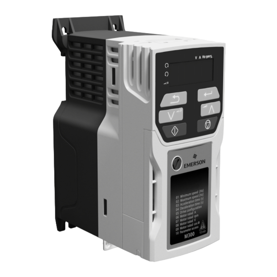
Page 18: Keypad And Display
Figure 5-1 Unidrive M200 keypad detail Figure 5-2 Unidrive M201 keypad detail V A Hz rpm % V A Hz rpm % (1) The Enter button is used to enter parameter view or edit mode, or to accept a parameter edit. -
Page 19: Saving Parameters
2. Select 'Def.50’ or 'Def.60' in Pr mm.000. (alternatively, enter 1233 (50 Hz settings) or 1244 (60 Hz settings) in Pr mm.000). 3. Either: • Press the red reset button • Carry out a drive reset through serial communications by setting Pr 10.038 to 100 Unidrive M200/201 Control Quick Start Guide Issue Number: 2... -
Page 20: Basic Parameters (Menu 0)
CoASt (0), rP (1), rP.dc I (2), 00.031 Stop Mode dc I (3), td.dc I (4), dis (5), rp (1) No.rP (6) Dynamic V to F 00.032 Select / Flux 0 to 1 RW Num Optimization Select Unidrive M200/201 Control Quick Start Guide Issue Number: 2... - Page 21 User (3) Frequency Controller 0.000 to 00.065 Proportional Gain 0.100 s/rad RW Num 200.000 s/rad 0.00 to Frequency Controller 00.066 RW Num 0.10 s /rad Integral Gain Ki1 655.35 s /rad Unidrive M200/201 Control Quick Start Guide Issue Number: 2...
- Page 22 ** If this parameter is read via serial communications, it will show pole pairs. Read / Read Number Binary Text string Filtered Write only parameter parameter parameter Protected Rating Power-down default User save DE Destination copied parameter dependent save value Unidrive M200/201 Control Quick Start Guide Issue Number: 2...
- Page 23 Unidrive M200/201 Control Quick Start Guide Issue Number: 2...
- Page 24 00.018 Reference 1 AV.Pr AI.Pr Pad.Ref Keypad reference E. Pot Input Read-write (RW) 00.XXX terminals parameter Read-only (RO) Output 00.XXX parameter terminals The parameters are all shown in their default settings Unidrive M200/201 Control Quick Start Guide Issue Number: 2...
- Page 25 Voltage Boost Speed 00.032 Dynamic V/f Select Motor Rpm 05.004 Power stage Maximum Switching 00.037 Frequency 05.001 Output Frequency RFC-A Current Torque Magnitude Producing 04.002 04.001 Current Magnetising Current Resistor optional Unidrive M200/201 Control Quick Start Guide Issue Number: 2...
-
Page 26: Unidrive M200/201 Parameter Descriptions
±VM_ACCEL_RATE s/100 Hz 5.0 s/100 Hz RFC-A Set Pr 00.003 at the required rate of acceleration. Note that larger values produce lower acceleration. The rate applies in both directions of rotation. Unidrive M200/201 Control Quick Start Guide Issue Number: 2... - Page 27 Pr 00.005 will change back to its previous value. When the setting of Pr 00.005 is changed, the appropriate drive configuration parameters NOTE are set back to their default values. Unidrive M200/201 Control Quick Start Guide Issue Number: 2...
- Page 28 Enter the motor rated power factor cos (taken from the motor name plate). The drive can measure the motor rated power factor by performing a rotating autotune (see Autotune (Pr 00.038). Unidrive M200/201 Control Quick Start Guide Issue Number: 2...
- Page 29 Drive parameters cannot be accessed via a comms/fieldbus interface in the drive or any option module. 00.015 {01.005} Jog Reference 0.00 to 300.00 Hz 1.50 Hz RFC-A Defines the reference when jog is enabled. Unidrive M200/201 Control Quick Start Guide Issue Number: 2...
- Page 30 Bipolar Reference Enable Off (0) or On (1) Off (0) RFC-A Pr 00.017 determines whether the reference is uni-polar or bi-polar. See Minimum Reference Clamp (00.001). Allows negative speed reference in keypad mode. Unidrive M200/201 Control Quick Start Guide Issue Number: 2...
- Page 31 Fst.bst (3) RFC-A Defines the mode used by the ramp system. 0: Fast ramp 1: Standard ramp 2: Standard ramp with motor voltage boost 3: Fast ramp with motor voltage boost Unidrive M200/201 Control Quick Start Guide Issue Number: 2...
- Page 32 Program Programming a parameter set to the NV Media Card Auto Auto save Boot Boot mode For further information, please refer to Chapter 9 NV Media Card Operation on page 49. Unidrive M200/201 Control Quick Start Guide Issue Number: 2...
-
Page 33: Unidrive M200/201 Control Quick Start Guide Issue Number
If a stator resistance is not measured, the drive may trip on 0 V or OI.AC while trying to catch a spinning motor. Pr 00.033 Text Function Disabled Enable Detect all frequencies Fr.Only Detect positive frequencies only Rv.Only Detect negative frequencies only Unidrive M200/201 Control Quick Start Guide Issue Number: 2... - Page 34 Drive running at zero frequency Drive (RDY) Drive OK Brake release Torque limiting (Valid while the torque is limited by torque limiting value 1/2) Forward or reverse Motor 1 or 2 Unidrive M200/201 Control Quick Start Guide Issue Number: 2...
- Page 35 3 kHz switching frequency 4 kHz switching frequency 6 kHz switching frequency 8 kHz switching frequency 12 kHz switching frequency 16 kHz switching frequency See the Drive User Guide for drive derating data. Unidrive M200/201 Control Quick Start Guide Issue Number: 2...
-
Page 36: Drive Enable 0
50 Hz: 50.00 Hz UNIPOLAR Hz 60 Hz: 60.00 Hz RFC-A Enter the value from the rating plate of the motor. Defines the voltage to frequency ratio applied to the motor. Unidrive M200/201 Control Quick Start Guide Issue Number: 2... - Page 37 It.AC or 0 V trips. 00.042 {05.015} Low Frequency Voltage Boost 0.0 to 25.0 % RFC-A Determines the boost level when Pr 00.041 is set to Fd, SrE or Fd.tap modes. Unidrive M200/201 Control Quick Start Guide Issue Number: 2...
- Page 38 00.046 {12.042} Brake Controller Upper Current Threshold 0 to 200 % 50 % RFC-A Defines the upper current threshold for the brake. See Brake Controller Brake Release in Drive User Guide. Unidrive M200/201 Control Quick Start Guide Issue Number: 2...
- Page 39 Defines the pre-brake release delay. See Brake Controller Brake Release in Drive User Guide. 00.051 {12.047} Brake Controller Post-brake Release Delay 0.0 to 25.0 s 1.0 s RFC-A Defines the post-brake release delay. Unidrive M200/201 Control Quick Start Guide Issue Number: 2...
- Page 40 I/O. Drive ok is routed to the relay output. If Brake Controller Enable (00.055) = 3, the brake controller is enabled, but no parameters are set up to select the brake output. Unidrive M200/201 Control Quick Start Guide Issue Number: 2...
- Page 41 4 (0), 5 (1), 6 (2), 8 (3), 12 (4), RFC-A 4 (0) ms 20 (5) ms Defines the time constant for the filter applied to the output of the frequency estimator system. Unidrive M200/201 Control Quick Start Guide Issue Number: 2...
- Page 42 0 to 999999 RFC-A Displays the software version in the drive. 00.079 {11.031} User Drive Mode OPEn.LP (1) OPEn.LP (1), RFC-A (2) RFC-A RFC-A (2) Defines the mode of the drive. Unidrive M200/201 Control Quick Start Guide Issue Number: 2...
-
Page 43: Running The Motor
To stop the motor under ramp control, open either the run forward or Stopping run reverse terminal. If the enable terminal is opened while the motor is running, the motor will coast to a stop. Unidrive M200/201 Control Quick Start Guide Issue Number: 2... -
Page 44: Diagnostics
Derivative file error Contact the supplier of the drive. dEr.I Derivative product image error Contact the supplier of the drive Unidrive M200/201 Control Quick Start Guide Issue Number: 2... - Page 45 Check integrity of the motor insulation using an insulation tester • Is the motor cable length within limits for the frame size • Reduce the values in the current loop gain parameters Unidrive M200/201 Control Quick Start Guide Issue Number: 2...
- Page 46 The option module installed in Slot 1 has started the option Option module watchdog function SL.tO watchdog function and then failed to service the watchdog service error correctly. Unidrive M200/201 Control Quick Start Guide Issue Number: 2...
- Page 47 A US.24 trip is initiated if the User Supply Select is set to 1 and US.24 the adaptor interface terminals no user 24 V supply is present on the user 24 V input on the AI- (1,2) Backup adaptor. Refer to the Drive User Guide. Unidrive M200/201 Control Quick Start Guide Issue Number: 2...
-
Page 48: Alarm Indications
Limit switch active. Indicates that a limit switch is active and that is causing the motor to be stopped. Lo.AC Low voltage mode. See Low AC Alarm in Drive User Guide. I.AC.Lt Current limit active. See Current Limit Active in Drive User Guide. Unidrive M200/201 Control Quick Start Guide Issue Number: 2... -
Page 49: Nv Media Card Operation
Drive User Guide for further information. The card should not be removed during data transfer, as the drive will produce a trip. If this occurs then either the transfer should be reattempted or in the case of a card to drive transfer, default parameters should be loaded. Unidrive M200/201 Control Quick Start Guide Issue Number: 2... -
Page 50: Analog Output
Digital I/O Analog I/O 24 V user Analog input 1+ Digital I/O1 Frequency Zero frequency reference 1 10 V user Digital Input 2 Drive enable Digital input 3 Analog input 2 Frequency Run forward reference 2 Digital input 4 Analog output 1 Run reverse Frequency output Digital input 5...