
Related Manuals for Emerson Unidrive M200-01100017


Summary of Contents for Emerson Unidrive M200-01100017
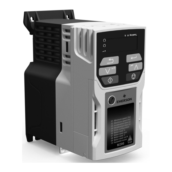
- Page 1 Quick Start Guide Unidrive M200/201 Frame sizes 1 to 4 Flexible machine integration through communications Part Number: 0478-0038-05 Issue: 5...
- Page 2 This guide is intended to provide basic information required in order to set-up a drive to run a motor. For more detailed installation information, please refer to the Unidrive M200 / 201 User Guide which is available to download from: www.controltechniques.com/userguides or http://www.emersonindustrial.com/en-EN/leroy-somer-motors-drives/downloads/Pages/ manuals.aspx.
-
Page 3: Table Of Contents
Contents Product information ..................6 Ratings ........................6 Options ......................7 Mechanical installation ................8 Electrical installation .................10 AC supply requirements ..................10 External braking resistor ..................10 Ground leakage ..................... 12 Control terminal configurations and wiring ............. 13 EMC ........................23 Keypad and display ...................25 Saving parameters .................... - Page 4 Declaration of Conformity Control Techniques Ltd Moteurs Leroy-Somer The Gro Usine des Agriers Newtown Boulevard Marcellin Leroy Powys CS10015 16915 Angoulême Cedex 9 SY16 3BE France This declaration applies to Unidrive M variable speed drive products, comprising models numbers as shown below: Maaa-bbcddddd Valid characters: 100, 101, 200, 201, 300, 400 01, 02, 03, 04, 05, 06, 07, 08...
- Page 5 These products comply with the Low Voltage Directive 2006/95/EC, the Electromagnetic Compatibility Directive 2004/108/EC. T. Alexander VP Technology Date: 29th May 2014 Place: Newtown, Powys. UK These electronic drive products are intended to be used with appropriate motors, controllers, electrical protection components and other equipment to form complete end products or systems.
-
Page 6: Product Information
Product information Ratings Nominal cable size Max input Output current fuse rating Max. European Input cont Max. phases input cont Nominal Motor Model 1 Ph 3 Ph Input Output Input Output current output power power current 01100017 0.25 0.33 01100024 11.1 0.37 01200017... -
Page 7: Options
Figure 1-1 Model number structure Derivative Electrical Specifications M200 - 00073 Product line: Drive Format : A – AC in AC out Frame size: Voltage rating Current Rating : 1 - 100 V (100 - 120 ± 10 %) Heavy Duty current rating x10 2 - 200 V (200 - 240 ±... -
Page 8: Mechanical Installation
Table 2.2 AI Backup adaptor Type Option module Name Further Details Communications AI-485 Adaptor See Drive User Guide Backup AI-Backup Adaptor Mechanical installation The drives can be panel mounted with 0 mm space between the drives. For further information on mechanical installation refer to the Drive User Guide. - Page 9 Table 3-1 Tools required Tool Location Size 1 Size 2 Size 3 Size 4 Small terminal screwdriver Control, relay terminals 3 mm Flat-bladed screwdriver Power terminals 5 mm Flat-bladed screwdriver Terminal cover Pozidrive 1 screwdriver AC power terminals Pozidrive 2 screwdriver Power terminals Torx 10 driver EMC &...
-
Page 10: Electrical Installation
Electrical installation An overlay of the electrical connections / terminals is included on the back page of this manual. AC supply requirements Voltage: 100 V drive: 100 V to 120 V ±10 % 200 V drive: 200 V to 240 V ±10 % 400 V drive: 380 V to 480 V ±10 % Number of phases: 3... - Page 11 Table 4-2 Braking resistor resistance and power rating (200 V) Minimum Instantaneous Continuous Model resistance* power rating power rating Ω 01200017 0.25 01200024 0.37 01200033 0.55 01200042 0.75 02200024 0.37 02200033 0.55 02200042 0.75 02200056 02200075 03200100 04200133 04200176 Table 4-3 Braking resistor resistance and power rating (400 V) Minimum Instantaneous Continuous...
-
Page 12: Ground Leakage
Ground leakage The ground leakage current depends upon whether the internal EMC filter is installed or not. The drive is supplied with the filter installed. Instructions for removing the internal filter are given in section 4.5.1 Internal EMC filter on page 23. With internal filter installed: Size 1: 2.5 mA* AC at 230 V 50 Hz (line to line supply, star point ground) -
Page 13: Control Terminal Configurations And Wiring
4.3.1 Use of residual current device (RCD) There are three common types of ELCB / RCD: 1. AC - detects AC fault currents 2. A - detects AC and pulsating DC fault currents (provided the DC current reaches zero at least once every half cycle) 3. - Page 14 Action will only occur if the drive is inactive, not in UU state and no User Actions are running. Otherwise, the parameter will return to its pre altered value on exit from edit mode. All parameters are saved if this parameter changes. Figure 4-1 Pr 00.005 = AV (50 Hz) Voltage speed reference input (AI 1)
- Page 15 Figure 4-2 Pr 00.005 = AV (60 Hz) Voltage speed reference input (AI 1) + 10 V output Voltage speed reference input (AI 2) Analog output 1 (motor frequency) + 24 V output Digital output (zero frequency) Not stop Jog forward Analog input 1/ input 2 select Figure 4-3 Pr 00.005 = AI (50 Hz)
- Page 16 Figure 4-4 Pr 00.005 = AI. (60 Hz) Current speed Current speed reference reference input input (AI 1) + 10 V output Voltage speed reference input (AI 2) Analog output 1 (motor frequency) + 24 V output Digital output (zero frequency) Not stop Jog forward Analog input 1/...
- Page 17 Figure 4-6 Pr 00.005 = AV.Pr (60 Hz) Voltage speed reference input (AI 1) + 10 V output Reference select Analog output 1 (motor frequency) + 24 V output Digital output (zero frequency) Terminal 5 Terminal 14 Reference selected Not stop Analog reference 1 (01.036) Preset speed 2 (01.022) Preset speed 3 (01.023)
- Page 18 Figure 4-8 Pr 00.005 = AI.Pr (60 Hz) Current speed Current speed reference reference input input (AI 1) + 10 V output Reference select Analog output 1 (motor frequency) + 24 V output Digital output (zero frequency) Not stop Terminal 5 Terminal 14 Reference selected Analog reference 1 (01.036) Preset speed 2 (01.022)
- Page 19 Figure 4-10 Pr 00.005 = Preset (60 Hz) Voltage speed reference input (AI 1) + 10 V output Reference select Analog output 1 (motor frequency) + 24 V output Digital output (zero frequency) Terminal 5 Terminal 14 Reference selected Not stop Preset speed 1 (01.021) Preset speed 2 (01.022) Preset speed 3 (01.023)
- Page 20 Figure 4-12 Pr 00.005 = Pad.Ref (50 Hz & 60 Hz) Voltage speed reference input (AI 1) + 10 V output Voltage speed reference input (AI 2) Analog output 1 (motor frequency) + 24 V output Digital output (zero frequency) Drive enable Run forward Run reverse...
- Page 21 Figure 4-14 Pr 00.005 = E.Pot (60 Hz) Voltage speed reference input (AI 1) + 10 V output DOWN When Pr 00.005 is set to E.Pot, the following parameters may need to be adjusted: • Pr 09.023: Motorized pot up/down rate (s/100 %) Analog output 1 (motor frequency) •...
- Page 22 Figure 4-16 Pr 00.005 = torque (60 Hz) Current speed Current speed reference reference input input (AI 1) + 10 V output Torque reference input (AI 2) When torque mode is selected and the drive is connected to an unloaded motor, the motor speed may increase rapidly to the maximum speed (Pr 00.002 +10 %) WARNING...
-
Page 23: Emc
Figure 4-18 Pr 00.005 = Pid (60 Hz) When Pr 00.005 is set to Pid, the following parameters may need to be adjusted: 4 - 20 mA PID PID feedback • Pr 14.010: PID proportional gain input (AI 1) feedback input •... - Page 24 Figure 4-19 Removal of the internal EMC filter (size 2 shown) To electrically disconnect the internal EMC filter, remove the screw as shown above (1). 4.5.3 Further EMC precautions Further EMC precautions are required if more stringent EMC emission requirements apply: •...
-
Page 25: Keypad And Display
Keypad and display The keypad and display provide information to the user regarding the operating status of the drive and trip codes, and provide the means for changing parameters, stopping and starting the drive, and the ability to perform a drive reset. Figure 5-1 Unidrive M100 keypad detail Figure 5-2 Unidrive M101 keypad detail V A Hz rpm %... -
Page 26: Saving Parameters
Saving parameters When changing a parameter in Menu 0, the new value is saved when pressing the Enter button to return to parameter view mode from parameter edit mode. If parameters have been changed in the advanced menus, then the change will not be saved automatically. -
Page 27: Basic Parameters (Menu 0)
Basic parameters (Menu 0) Menu 0 is used to bring together various commonly used parameters for basic easy set up of the drive. All the parameters in Menu 0 appear in other menus in the drive (denoted by {…}). Menus 22 can be used to configure the parameters in Menu 0. - Page 28 Range Default Parameter Type RFC-A RFC-A Catch A Spinning dis (0), Enable (1), Fr.Only (2), 00.033 dis (0) Motor Rv.Only (3) Input (0), th.Sct (1), th (2), 00.034 Digital Input 5 Select Input (0) th.Notr (3), Fr (4) Digital Output 1 00.035 0 to 21 Control...
- Page 29 Range Default Parameter Type RFC-A RFC-A Maximum Heavy 00.077 0.00 to 9999.99 A RO Num ND NC PT Duty Current Rating 00.078 Software Version 0 to 999999 ND NC PT 00.079 User Drive Mode OPEn.LP (1), RFC-A (2) OPEn.LP (1) ND NC PT US LEVEL.0 (0), ALL (1), r.only.0 (2), 00.080 User Security Status...
- Page 30 Figure 6-1 Menu 0 logic diagram Analog input 1/ input 2 select Analog reference 00.016 Analog input Analog input 1 1 mode Analog input 2 01.050 01.015 01.050 Bipolar >1 Reference Drive Enable Configuration 00.017 00.005 Preset frequency reference Preset 00.018 Reference 1 AV.Pr...
- Page 31 OL, RFC-A> AT ZERO TORQUE FREQUENCY FREQUENCY FORWARD REVERSE Analog outputs Digital output Maximum Reference Clamp Ramp 00.002 Enable Minimum 00.029 Reference Clamp Torque Mode 04.011 Selector 00.001 00.033 RFC-A mode only Motor parameters 00.006 ~ 00.009 Ramps Motor Rated Current Motor Rated Speed RFC-A Frequency-loop Motor Rated Voltage...
-
Page 32: Running The Motor
Running the motor This section takes a new user through all the essential steps to running a motor for the first time. Table 7-1 Open Loop and RFC-A Action Detail Ensure: • The drive enable signal is not given, terminal 11 is open •... -
Page 33: Nv Media Card Operation
NV Media Card Operation Figure 8-1 Installing the AI-Backup adaptor (SD Card) 1. Identify the two plastic fingers on the underside of the AI-Backup adaptor (1) - then insert the two fingers into the corresponding slots in the spring-loaded sliding cover on the top of the drive. 2. -
Page 34: Ul Listing Information
UL listing information General Drive sizes 1 to 4 have been assessed to meet both UL and cUL requirements. UL listings can be viewed online at www.UL.com. The UL file number is E171230. Mounting Drives can be installed in the following configurations: •... -
Page 35: Cul Requirements For Frame Size 4
cUL requirements for frame size 4 For frame size 4, models Mxxx-042 00133A, Mxxx-042 00176A, Mxxx-044 00135A and Mxxx-044 00170A, transient surge suppression shall be installed on the line side of this equipment and shall be rated 480 Vac (phase to ground), 480 Vac (phase to phase), suitable for overvoltage category III, and shall provide protection for a rated impulse withstand voltage peak of 6 kV and a clamping voltage of maximum 2400 V. -
Page 36: Group Installation
9.11 Group installation 9.11.1 Definition Group Installation Definition: A motor branch circuit for two or more motors, or one or more motors with other loads, protected by a circuit breaker or a single set of fuses. 9.11.2 Limitations on use All motors rated less than 1 hp The drives may be used in group installations where each of the motors is rated 1 hp or less. - Page 38 Digital I/O Analog I/O 24 V user Analog input 1+ Digital I/O1 Frequency Zero frequency reference 1 10 V user Digital Input 2 Drive enable Digital input 3 Analog input 2 Frequency Run forward reference 2 Digital input 4 Analog output 1 Run reverse Frequency output Digital input 5...