GE JGS968 Service Manual
30" slide-in convection gas self-clean range
Hide thumbs
Also See for JGS968:
- Owner's manual (101 pages) ,
- Technical service manual (63 pages) ,
- Installation instructions manual (33 pages)
Available languages
Available languages
Quick Links
See also:
Owner's Manual, Technical & Service Manual
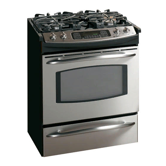
30" SLIDE-IN CONVECTION
GAS SELF-CLEAN RANGE
MODEL NUMBER
JGS968
IMPORTANT SERVICE INFORMATION
DO NOT DISCARD
IMPORTANT SAFETY NOTICE: This information is intended for use by individuals
possessing adequate background of electrical, electronic and mechanical experience.
Any attempt to repair a major appliance may result in personal injury and property
damage. The manufacturer or seller cannot be responsible for the interpretation of
this information, nor can it assume any liability in connection with its use.
DISCONNECT POWER BEFORE SERVICING.
IMPORTANT: RECONNECT ALL GROUNDING DEVICES.
All parts of this appliance capable of conducting electrical current are grounded. If grounding
wires, screws, straps, clips, nuts or washers used to complete a path to ground are removed
for service, they must be returned to their original position and properly fastened.
NOTE: Installation information for reference only.
See Installation Instructions shipped with product
WARNING
for complete details and before attempting to install.
Anti-tip bracket must be attached to the floor or wall to
• All ranges can tip
• Injury to persons could result
hold either right or left rear leg leveler. Make sure leg
• Install anti-tip bracket
leveler reengages the bracket when range is moved
packed with range
• See Installation Instructions
for any reason.
Attachment to Wall
Attachment To Wall
Adjacent Cabinet
Adjacent Cabinet
or Final Location of
Wall
Wall Plate
Or Final Location
Range Side Panel
Bracket
Bracket
Plate
Wall
Of Range Side Panel
Wall
FLOOR–WOOD
Floor-Wood
Bracket Side
Screw Must
Bracket
Screw Must
Side
Enter Wood
Enter Wood or
Rear
Or Metal
Metal
Rear
Leveling
Floor-Concrete
FLOOR–CONCRETE
Leveling Leg
Leg
IMPORTANT INSTALLATION INFORMATION
1. This model is shipped with a filler strip. Please read installation instructions for use.
2. L.P. Gas Conversion—Required information in installation instructions.
3. After servicing, make sure the range leg levelers completely engage the anti-tip bracket.
4. Some vinyl wall tiles and floor coverings, as well as some indoor-outdoor carpeting, soften
at fairly low temperatures. If you are unsure of the heat resistance of a material, put a
protective covering under the range to prevent possible heat damage during range use.
5. Make sure the wall coverings, countertop and cabinets around the range can withstand
the heat (up to 194°F) generated by the range.
The cabinet must have solid sides and a solid back. The floor upon which the
range sits must be solid also. Any openings around the gas or electrical outlets
must be sealed. All cabinet openings must be sealed at the time of installation
to prevent drafts. Drafts will affect safe use of the oven.
OVEN GAS SHUT-OFF VALVE
Gas Supply
to Oven
The gas shut-off valve is located on the side of the
pressure regulator which is mounted to the back of
Shut-Off Lever
the range. Access to the shut-off lever is obtained
Shown in the
by removing the storage drawer and reaching
Open Position
Gas Supply to
Top Burner
through the opening on the right side of the control box.
NOTE: The oven shut-off valve shuts off the gas to
the oven only and has no effect on the top burners.
Pressure Regulator as Seen
Pressure Regulator
as see from Front of
from Front of Range
Range
REMOVABLE OVEN DOOR
Slot
The door is very heavy. Be careful when removing and lifting the door.
Do not lift the door by the handle.
TO REMOVE:
1. Fully open the door.
2. Push the hinge locks down toward the door frame, to the unlocked
position. A tool, such as a small flat-blade screwdriver, may be required.
Hinge
3. Firmly grasp both sides of the door at the top.
Lock
Pull hinge locks
4. Close door to the door removal position, which
down to unlock
is halfway between the broil stop position and
fully closed.
5. Lift door up until the hinge arm is clear of the slot.
Removal position
229C4059P613
TO REPLACE:
Bottom Edge
Hinge Arm
of Slot
1. Firmly grasp both sides of the door at the top.
2. With the door at the same angle as the removal
position, seat the indentation of the hinge arm into the
bottom edge of the hinge slot. The notch in the hinge
arm must be fully seated into the bottom of the slot.
Indentation
Hinge Lock
3. Fully open the door. If the door will not fully open, the
indentation is not seated correctly in the bottom edge
of the slot.
4. Push the hinge locks up against the front frame of the
oven cavity, to the locked position.
Hinge Arm
5. Close the oven door.
Push hinge locks up to lock
BURNER OUTPUT RATING:
NATURAL GAS 4" W.C.P.
BTU RATE
KW
ORIF. SIZE
REPAIR PART
BURNER
RF
15,000
—
No. 49
RR
6,000
—
No. 56
LF
11,000
—
No. 52
LR
9,100
—
No. 54
BAKE
15,000
—
—
BROIL
12,000
—
—
BURNER OUTPUT RATING:
L.P. (PROPANE) GAS 10" W.C.P.
REPAIR PART
BURNER
BTU RATE
KW
ORIF. SIZE
RF
13,000
—
No. 59
RR
5,200
—
No. 69
LF
9,100
—
No. 63
LR
8,000
—
No. 65
BAKE
15,000
—
—
BROIL
12,000
—
—
SEALED SURFACE BURNER
Spark
Ignitor
Burner Grate
Burner Cap
Burner Head
Spark Ignitor
Glass Maintop
Burner Base
MAINTOP REMOVAL AND ACCESS TO SPARK MODULE
1. Cut off gas supply to range.
2. Cut off electrical supply to range.
3. Remove the control panel as follows:
a) Remove knobs.
b) Unscrew and remove hexagonal control panel fasteners.
c) Lift the control panel glass and remove the ribbon connector.
d) Remove hex head screws from metal insert.
e) Lift off insert/clock assembly.
f) Remove the 3 amp connectors from the electronic clock.
g) Disconnect the 12 pin amp connector.
h) Remove the upper hex head screws holding the control panel to the maintop frame.
i) Remove the lower screws holding the control panel to the maintop baffle.
(NOTE: These are accessed through the top of the oven cavity behind the door.)
j) Remove the control panel.
4. Remove the gas fitting (right side) connecting the gas manifold to the gas supply line.
5. Remove two screws, one right, one left holding the maintop to the range frame.
6. Unscrew and remove the oven cavity vent using a 1/2 inch socket and turn counterclockwise.
7. Lift off the maintop by sliding foward. NOTE: Take care to miss the oven cavity vent when
sliding foward.
SURFACE BURNER ADJUSTMENTS
Standard adjustments to the air shutter and gas metering orifices are not possible on sealed burners.
If burner flames appear to be abnormal, check the following:
• Check gas pressure available to the burners. The required operating pressure is 4" W.C.P. Natural
Gas or 10" W.C.P. LP (Propane) Gas. The pressure reading can be taken at the BROIL, BAKE or
TOP burner orifices.
• Check for drafts entering the burner box from behind the range. Strong drafts beneath the maintop
can extinguish the burner and/or cause erratic burner flames.
• Check for blockage or partial blockage of the orifice. Inspect the orifice to be sure it has been
drilled on center and is free of debris or burrs.
• Check the burner alignment per the “Burner Alignment” section of this manual.
• If the flames blow and lift off the burner and the cause of the problem cannot be found, installing
an orifice with smaller diameter openings may solve the problem. In high altitude (above 6000 ft.)
installation, the orifices will usually have to be downsized.
SMALLER ORIFICES ARE AVAILABLE AS LISTED BELOW:
Smaller Orifices for Natural Gas:
Smaller Orifices for LP Gas:
Burner
Size
Part Number
Burner
Size
Part Number
No. 51
WB28T10091
No. 60
WB28K10086
RF
RF
No. 56
WB28K10085
No. 70
WB28K10085
RR
RR
LF
No. 53
WB28T10014
LF
No. 64
WB28K10087
No. 54
WB28T10017
No. 66
WB28T10017
LR
LR
MAINTOP BURNER ALIGNMENT
For proper operation of the burner, alignment of the orifice holder, orifice and air/gas mixer tube must
be correct. The alignment can be checked by placing 7mm or 9/32" nutdriver over the orifice to
exaggerate the angle. The nutdriver should stand straight, indicating the alignment and gas injection
angle is correct. A slight downward pressure may be necessary to seat the nutdriver over the “Orifice
Retainer Ring”.
If an angle adjustment is necessary, remove the burner cap, head and bowl to inspect the orifice
holder and the brackets that hold them in place. Adjust as necessary. A misaligned burner may
result in uneven flames around the burner head.
LOW FLAME SIMMER ADJUSTMENTS
Remove the surface control knob and locate the adjustment screw on the valve body at about the
6 o’clock position.
NOTE: Low setting adjustments must be made with two other burners in operation on a
medium setting. This procedure prevents the low flame from being set too low, resulting
in the flame being extinguished when other burners are turned on.
TEST THE FLAME STABILITY
Test 1: Turn the knob from “HI” to “LOW” quickly. If the low flame goes out, increase the flame size
and test again.
Test 2: With the burner on “LOW” setting, open and close the oven door quickly. If the flame is
extinguished by the air currents created by the door movement, increase the flame height and
test again.
ACCESS TO CONTROL VALVE:
The control valve for this product is not front serviceable. There is a test plug available through
the control panel that will allow a check of amperage to verify continuity. The amperage should be
between 3.4 AMP 3.6 at 116 ± 1 volt.
IN CASE THE CONTROL VALVE NEEDS REPLACING, FOLLOW THESE STEPS:
1. Shut off the gas to the range.
2. Shut off power to the range.
3. Pull range out from the cabinet to expose the control valve.
Reverse the steps for repositioning.
NOTE: Make sure the anti-tip bracket is installed correctly when pushing the range back into place.
ACCESS TO BAKE AND BROIL BURNERS AND
BAKE AND BROIL BURNER IGNITORS:
1. Remove oven door.
2. Remove oven racks.
FOR BAKE BURNERS AND BAKE BURNER IGNITORS:
1. Remove oven bottom by lifting at front and sliding forward.
2. Remove flame spreader by unscrewing four hex head screws.
3. Remove air shutter shield for access to air shutter and bake orifice, if needed.
FOR BROIL BURNERS AND BROIL BURNER IGNITORS:
1. Remove lower burner shield by unscrewing two hex head screws.
NOTE: Make sure the ignitor wires are pushed back into and through the insulation to prevent
touching the oven cavity back.
When maintenance and/or adjustments are completed, reverse the assembly process prior to
range use.
OVEN BURNER IGNITION SYSTEM
The oven burners are ignited by a glowbar ignition system. The ignitor is a “Norton” style rectangular
glowbar. The bake and broil ignition circuits consist of the electronic control, an ignitor and an oven
safety valve (gas valve). The three components are wired in series for each cooking function.
The most important points to know about the ignition system are:
1. THE IGNITER RESISTANCE DECREASES AS THE IGNITOR SURFACE TEMPERATURE
INCREASES.
2. THE SAFETY VALVE OPERATES BY CURRENT, NOT VOLTAGE.
From a cold start, the ignitor needs 30–60 seconds, with a minimum of 116 volts applied, to reduce
its electrical resistance enough to provide a minimum of 2.9 amps of current flow in the series circuit.
This is the required current flow needed for the safety valve to open and supply gas to the burner.
The glowbar should provide a steady current flow of between 3.4 to 3.6 amps in the circuit. At that
point the ignitor temperature is between 1800 to 2500 degrees F. The ignitor will remain energized
at all times during burner operation. If the ignitor glows red but does not draw at least 2.9 amps,
the fault is usually with the ignitor, not the valve. Always check the oven shut-off valve for a
“Not On” condition.
GLOWBAR IGNITION CIRCUIT
WARNING: The “Norton” glowbar ignitor is NOT INTERCHANGEABLE with the
“Carborundum” glowbar ignitor. The two types of glowbar ignitors operate at different
amperages and use different gas valves.
NOTE: Check system with clamp-on ammeter. If ignitor glows red but circuit does not draw at least
2.9 amps, the fault is likely with the ignitor, not the valve.
NOTE: If ignitor glows, but ignition does not occur, be sure the oven shut-off valve is in the open
position.
SLOW IGNITION CAN BE CAUSED BY ONE OR MORE OF THE FOLLOWING CONDITIONS:
1. Blockage of primary air intake: Hole beneath the bake orifice hood must be open and free
of insulation.
2. Blockage of secondary air intake holes: Examine oven burner box (galvanized box surrounding
oven burner) and inspect the single row of secondary air holes beneath the bake burner for signs
of blockage. Also, be sure items in the storage drawer do not push against the ceiling of the
drawer area. If pushed hard enough, the ceiling will flex upward, closing off the secondary air
holes.
3. Improper alignment of orifice hood and burner: Orifice must be pointing straight into burner
venturi.
4. Improper air/gas adjustment.
5. Blockage of burner crossover slots: Crossover slots must be open and free of burrs.
6. Improper installation: Failure to seal all openings in the wall behind and floor below range may
permit substantial drafts which can affect ignition.
7. The gas control valve should draw 5 amps when operating. This can be checked by measuring
the amperage in L1 to the oven control. This can be done by removing the control panel glass
and clock / insert assembly.
ELECTRONIC OVEN CONTROL (HP)
CAUTION: Components are electrically HOT on control when voltage is connected to range.
See section on sensor and lock
switch connector
The Electronic Oven Control system consists of the control, key panel, oven sensor, door and
lock assembly.
The key panel (control panel) and electronic control are separate components but must be tested
together.
KEY PANEL TEST
Press each pad on the key panel followed by the start pad. If the key panel is functioning properly,
the following should occur:
• BAKE, BROIL, CONVECTION BAKE, CONVECTION ROAST, CLEAN, TIMER, CLOCK, STOP TIME,
COOK TIME, PROOF, PROBE and RANGE LOCKOUT Modes – Audible tone plus display showing
mode of operation selected.
• CLEAR/OFF – Audible tone and display shows time of day.
• PROBE – Audible tone and response if meat probe is plugged in.
• Numerical Pads – Audible tone. Can only be used after another function has been selected.
RELAY CONTACTS OPERATION TEST AND
CONTROL VOLTAGE CHECK
TERMINALS
VOLTAGE
L1- TO N
120 VAC ALL THE TIME
BAKE TO N
120 VAC when in BAKE mode
BROIL TO N
120 VAC when in BROIL mode
SWITCH CONTACTS
DOOR MOTOR TO N
120 VAC locking or unlocking
NOTE: Temperature/Mode Selection Necessary for operation of Relay contacts.
NOTE: Voltage must be present across terminals L1 to N for control to operate. Transformer
primary is 150 to 200Ω measured “L1” to “N” with power removed.
OVEN SENSOR AND DOOR SWITCH OHMMETER TEST
(See “Motorized Door Lock Operation” for door switch function explanation.) Remove power from
oven. Make resistance measurement from side of sensor and lock switch connector, with
exposed terminals disconnected from control.
OVEN SENSOR AND LOCK SWITCH CONNECTOR
MEAT PROBE*
CONVECTION BAKE
1
50K @ RM
L1
N
2
LOCK
UNLOCK
SW. 1
3
SW. 2
4
5
THERMAL
LOW SPEED
6
SWITCH
DBL RELAY
7
OPEN @275°F
M
CLOSES @205°F
HI SPEED
8
CONVECTION
CONTROL
MOTOR
OVEN TEMP SENSOR
CONNECTOR
1100Ω @ ROOM TEMP
PLUG
2650Ω @ CLEAN TEMP
BROIL & CLEAN UNTIL/AFTER 750˚F IS REACHED
BAKE AND TIME BAKE
L1
N
L1
N
BLACK
BLACK
BAKE RELAY
L1
BK
BROIL RELAY
BROIL RELAY
BR
L1
L1
Bake & Broil relays cannot be on at same time.
** If convection fan is not working, make the following checks:
• Check the voltage from terminal CF to N on control—it should read 120V in Conv Bake or Roast
mode. If not, replace the control.
• If voltage is OK, check the convection fan motor. It reads approximately 15–20Ω at room
temperature. Check to make sure the fan shaft is not rubbing on the oven liner.

Related Manuals for GE JGS968


Summary of Contents for GE JGS968
- Page 1 No. 51 WB28T10091 No. 60 WB28K10086 arm must be fully seated into the bottom of the slot. venturi. Indentation JGS968 4. Improper air/gas adjustment. Hinge Lock No. 56 WB28K10085 No. 70 WB28K10085 3. Fully open the door. If the door will not fully open, the 5.
- Page 2 OVEN SENSOR AND DOOR LOCK SWITCH SELF-CLEAN & MOTORIZED DOOR LOCK REMOVABLE OVEN DOOR FAILURE OPERATION LOCK CIRCUITS COMPONENT COMPARTMENT AIRFLOW CODE MEANING CORRECTION MOTORIZED DOOR LOCK -F2- The motorized door lock assembly is located above the oven. The assembly consists of a lock motor Over temperature •...
- Page 3 WB28K10086 inférieur de la fente de la charnière. L'encoche du bras de galvanisée entourant le brûleur) et inspectez la rangée des trous d'air secondaires sous le brûleur JGS968 charnière doit être bien installée dans le bas de la fente. Enfoncement N°...
- Page 4 CONNECTEUR DU COMMUTATEUR DE VERROU ET CAPTEUR DU FOUR VERROU DE PORTE MOTORISÉ ET AUTONETTOYAGE PORTE DE FOUR AMOVIBLE CODE DE VERROU DE PORTE MOTORISÉ DEFAILLANCE SENS CORRECTION FONCTIONNEMENT DES CIRCUITS DE VERROUILLAGE DÉBIT D'AIR DU COMPARTIMENT DE COMPOSANTS L'assemblage de verrou de porte motorisé se trouve au-dessus du four. L'assemblage comprend une Court-circuit de la touche Il y a deux circuits contrôlant le verrouillage et le déverrouillage de la porte.