GE Profile J2S968 SERIES Technical Service Manual
Profile dual fuel and profile all gas slide-in ranges
Hide thumbs
Also See for Profile J2S968 SERIES:
- Owner's manual (97 pages) ,
- Installation instructions manual (41 pages) ,
- Instructions (4 pages)

Related Manuals for GE Profile J2S968 SERIES


Summary of Contents for GE Profile J2S968 SERIES
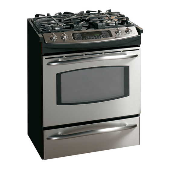
- Page 1 GE Consumer Products TECHNICAL SERVICE GUIDE Profile Dual Fuel and Profile All Gas Slide-In Ranges MODEL SERIES: J2S968 JGS968 JGSP48 PUB # 31-9105 07/03...
- Page 2 If grounding wires, screws, straps, clips, nuts, or washers used to complete a path to ground are removed for service, they must be returned to their original position and properly fastened. GE Consumer Products Technical Service Guide Copyright © 2003 All rights reserved.
-
Page 3: Table Of Contents
Table of Contents Adjusting the Oven Thermostat ..................18 Bake and Broil Burner Flame Adjustments ..............30 Bake Burner Glow-bar Igniter ................... 28 Bake Element (Dual Fuel) ....................32 Broil Burner Glow-bar Igniter .................... 28 Broil Element (Dual Fuel) ....................32 Component Locator Views .................... - Page 4 Table of Contents (Cont.) Range Components ......................24 Range Removal ....................... 25 Range Top Components ....................40 Relay Contacts Operation Test and Control Voltage Check ..........52 Serial Number ........................6 Schematics and Wiring Diagrams ................... 56 Special Oven Control Features ..................9 Spark Igniter ........................
-
Page 5: Introduction
Introduction Dual Fuel Range All Gas Range The new 30-in. Slide-In Dual Fuel and All Gas The convection baking and roasting feature Ranges make an eloquent statement of style, provides even cooking and superior baking every convenience, and kitchen planning flexibility. The time. -
Page 6: Serial Number
Nomenclature Model Number J 2 S 9 6 8 B Product J = GE Cooking Product Fuel 2 = Dual Fuel G = Gas Color B = Black Configuration S = Slide-In Feature Pack Designates features–the higher Oven Type the number, the more features. -
Page 7: Warranty
Any part of the range which fails due to a defect in materials or workmanship. During this From the date of the full one-year warranty, GE will also provide, free of charge, all labor and in-home service to original purchase replace the defective part. -
Page 8: Using The Oven Controls
Control Features Using the Oven Controls (Throughout this manual, features and appearance may vary from your model.) Features and appearance may vary. Oven Control, Clock and Timer Features and Settings BAKE Pad OVEN LIGHT ON/OFF Pad Touch to select the bake function. Touch to turn the oven light on or off. -
Page 9: Special Oven Control Features
Special Oven Control Features Your new touch pad control has additional features that you may choose to use. The following are the features and how you may activate them. The special feature modes can only be activated while the display is showing the time of day. They remain in the control’s memory until the steps are repeated. - Page 10 Special Oven Control Features Tone Volume This feature allows you to adjust the tone Touch the OVEN LIGHT ON/OFF pad volumes to a more acceptable volume. There are again. The display will show 1 BEEP. three possible volume levels. This is the quietest volume level. Touch the BROIL HI/LO and BAKE For each time the level is changed, pads at the same time for 3 seconds,...
-
Page 11: Using The Clock And Timer
Using the Clock and Timer To Set the Clock The clock must be set to the correct time Touch the CLOCK pad. of day for the automatic oven timing Touch the number pads. functions to work properly. The time of Make sure the clock is set to the day cannot be changed during a timed Touch the START pad. -
Page 12: Using The Timed Baking And Roasting Features
Using the Timed Baking and Roasting Features NOTE: Foods that spoil easily—such as milk, eggs, fish, stuffings, poultry and pork—should not be allowed to sit for more than 1 hour before or after cooking. Room temperature promotes the growth of harmful bacteria. Be sure that the oven light is off because heat from the bulb will speed harmful bacteria growth. -
Page 13: Using The Probe
Using the Probe How to Set the Oven For Roasting When Using the Probe (on some models) Insert the probe into the food. After the internal temperature of the food reaches 100°F, the changing Plug the probe into the outlet in the internal temperature will be shown in oven. -
Page 14: Using The Timed Features For Convection Cooking
Using the Timed Features for Convection Cooking You will hear a fan while cooking with these features. The fan will stop when the door is opened, but the heat will not turn off. NOTE: Foods that spoil easily—such as milk, eggs, fish, stuffings, poultry and pork—should not be allowed to sit for more than 1 hour before or after cooking. - Page 15 Using the Timed Features for Convection Cooking How to Set a Delayed Start and Automatic Stop You can set the oven control to delay-start the oven, Touch the number pads to set the cook for a specific length of time and then turn off desired cooking time.
-
Page 16: Using The Convection Oven
Using the Convection Oven How to Set the Oven for Convection Baking or Roasting Touch the CONVECTION BAKE Touch the number pads to set the MULTI/1 RACK pad once desired oven temperature. (depending on model) (CONVECTION BAKE MULTI mode) Touch the START pad. for multi-rack convection baking. - Page 17 Using the Proofing and Warming Features How to Set the Oven For Warming (on some models) ■ The WARM feature keeps cooked Check crispness after 20–30 minutes. foods hot. Add time as needed. This feature is not designed to reheat IMPORTANT NOTES: cold food.
-
Page 18: Adjusting The Oven Thermostat
Adjusting the Oven Thermostat You may find that your new oven cooks differently than the one it replaced. Use your new oven for a few weeks to become more familiar with it. If you still think your new oven is too hot or too cold, you can adjust the thermostat yourself. - Page 19 Using the Self-Cleaning Oven How to Delay the Start of Cleaning Touch the SELF CLEAN LO/STD pad The door locks automatically. The display will show the start time. It will once for a 4-hour clean time or twice for a 3-hour clean time. not be possible to open the oven door until the temperature drops below the A 3-hour self-clean time is...
-
Page 20: Using The Sabbath Feature
Using the Sabbath Feature (Designed for use on the Jewish Sabbath and Holidays.) (On some models) The Sabbath feature can be used for baking/roasting only. It cannot be used for convection, broiling, self-cleaning or Delay Start cooking. NOTE: The oven light comes on automatically (on some models) when the door is opened and goes off when the door is closed. The bulb may be removed. -
Page 21: Component Locator Views
Component Locator Views Dual Fuel Range Top Locator View Cooling Fan Bake Thermal Switch Thermal Switch Meat Probe Wires Door Latch Assembly All Gas Range Top Locator View Vent Cooling Fan Thermal Switch Meat Probe Wires Door Latch Assembly – 21 –... - Page 22 Rear View (Dual Fuel) Sensor Wire Top Burner Wires Maintop Burner Gas Line Convection Element Wires Fan Motor Fan Start Capacitor Bottom Burner Wires Pressure Regulator Rear View (All Gas) Maintop Burner Gas Line Glow-bar Wires Broil Burner Gas Line Fan Motor Gas Control Bake Burner Gas Line...
- Page 23 Maintop Burner Assembly Note: The Dual Fuel and All Gas Ranges have identical maintop burner assemblies except for the vent. The All Gas Range has a vent opening in the glass cooktop, the Dual Fuel Range does not. Bottom View Burner Valve Burner Valve Spark Module...
-
Page 24: To Replace Oven Door
Range Components Door Assemblies Oven Door The doors can be separated into two assemblies: WARNING: Before servicing the range, power (1) Outer assembly which consists of handle, and/or gas must be removed from the range. vent trim, outer glass, bottom trim, and frame; (2) Make sure the oven is completely cool. -
Page 25: Range Removal
To replace the door: 4. To replace the storage drawer, place the drawer rail on the guides. 1. Firmly grasp both sides of the door at the top. 5. Push the drawer in until it stops. 2. With the door at the same angle as the removal position, seat the indentation of the 6. -
Page 26: Oven Gas Shut-Off Valve (All Gas)
4. For improved lighting inside the oven, clean Oven Light Bulbs the glass cover frequently using a wet cloth. This should be done when the oven is Socket completely cool. Receptacle 5. Reconnect electrical power to the oven. Oven Gas Shut-off Valve (All Gas) The gas shut-off valve is located on the side of the pressure regulator which is mounted on a bracket Bulb... -
Page 27: Glow-Bar Igniter (All Gas)
Oven Components Check the glow-bar circuit with a clamp-on Oven Burner Ignition System (All Gas) ammeter. If igniter glows red but circuit does not The oven bake and broil burners are ignited by a draw at least 2.9 amps, the fault is likely with the igniter, not the valve. -
Page 28: Bake Burner Glow-Bar Igniter
5. Gently pull the glow-bar connector through the Broil Burner Glow-bar Igniter oven wall. Disconnect the glow-bar igniter wires. The broil burner glow-bar igniter has an approximate resistance value of 141 Ω. To remove the broil burner glow-bar igniter: 1. Remove the oven door (see Oven Door). Glow-bar Connector 2. - Page 29 7. Remove the bake burner. 3. Remove the 4 screws that hold the burner baffle in place. Note: When reinstalling the broil burner, make sure the burner inlet opening is over the gas outlet. Slot Burner Baffle Burner Gas Outlet Burner Inlet Opening 4.
-
Page 30: Bake And Broil Burner Flame Adjustments
To correct any flame problems, perform the Bake and Broil Burner Flame following procedures: Adjustments Bake Burner Note: A small amount of odor is normal and will be present when the range is first turned on. If 1. Remove the oven door (see Oven Door). there is a strong odor, the bake and broil burner 2. - Page 31 6. Adjust the air shutter to Broil Burner a. If the flames were yellow during the test, The broil burner is accessible and located in the open the air shutter an additional top rear of the oven. (.79 mm). 1. Remove the oven door (see Oven Door). b.
-
Page 32: Broil Element (Dual Fuel)
Bake Element (Dual Fuel) Broil Element (Dual Fuel) The bake element has an approximate resistance The broil element has an approximate resistance value of 22 Ω. value of 16 Ω. To remove the bake element: To remove the broil element: 1. -
Page 33: Fan Cycle Information
Convection Fan Assemblies The convection fan assembly consists of the fan guard, element (Dual Fuel Range), fan blade, and motor. It is located on the back wall of the oven. Refer to the schematic in the back of this manual for circuitry for your specific model. Note: The JGSP48 All Gas Range models do not have convection fans. -
Page 34: Convection Fan Motor
Convection Fan Motor Convection Fan Guard To remove the fan motor the range must be To remove the convection fan guard: removed from its installation. 1. Remove the oven door (see Oven Door). To remove the convection fan motor: 2. Remove 4 hex-head screws that secure the 1. - Page 35 6. Disconnect the wiring harness connector Dual Fuel Range Convection Fan Circuit from the motor. 7. Remove the 3 mounting hex-head screws and the motor. CONVECTION BAKE 240V. Dual Fuel Range Fan Motor 10.4A RELAY 10.4A CONV-1 CONVECTION BAKE ELE. 2500W L1-1 CONVEC...
-
Page 36: Control Valve (All Gas)
Dual Fuel All Gas Meat Probe Outlet The meat probe outlet is located toward the front of the oven next to the bake element on the Dual Fuel Range and the right corner of the All Gas Range. 1. Place the control panel in the service position (see Keypanel and ERC). -
Page 37: Oven Vent (Dual Fuel)
Oven Vent (Dual Fuel) Bake Thermal Switch The oven is vented above the left side of the door. Tube It is normal for steam to come out of this vent and Screw the area around the vent to become hot during oven use. -
Page 38: Control Panel Assembly
Control Panel Assembly WARNING: Components are electrically HOT when voltage is connected to range. The Control Panel Assembly consists of the electronic oven control (ERC) and keypanel. 5. Remove the 8 hex-head screws that secure Keypanel and ERC the ERC panel. The keypanel and ERC are separate components but must be tested together. -
Page 39: Convection Element (Dual Fuel)
Electronic Oven Control (ERC) Pin Locator All Gas Range with Convection Fan 1 - 120-VAC Power In 5 - Broil Burner Glow-bar Igniter 2 - Cooling Fan 6 - Bake Burner Glow-bar Igniter 3 - Oven Light 7 - Meat Probe, Oven Sensor, Door Lock/Unlock Switches 4 - Convection Fan 8 - Keypanel Ribbon Dual Fuel Range with Convection Fan... -
Page 40: Range Top Components
Range Top Components The range top components consist of the following: Maintop burner assembly (glass cooktop, burners, burner caps and heads, igniter and switches, spark module), cooling fan, thermal switches, door lock motor assembly, heat shields, and seals. Burner Output Rating Chart Surface Burner Adjustments BURNER OUTPUT RATING: Standard adjustments to the air shutter and gas... -
Page 41: Glass Cooktop
4. Open the door and remove the 5 hex-head Testing the Flame Stability screws under the control panel frame. Test 1: Turn the knob from HI to LOW quickly. If Remove the control panel frame. the low flame goes out, increase the flame size 5. -
Page 42: Spark Igniter
Igniter Switches and Harness Spark Igniter The 4 igniter switches and harness are replaced To remove the spark igniter: as 1 unit. 1. Remove the iron burner grate, burner cap, and 1. Remove the control panel assembly (see burner head from the glass cooktop. Keypanel and ERC). -
Page 43: Upper And Lower Heat Shields
4. Roll the lower heat shield back to access oven Upper and Lower Heat Shields components. The upper and lower heat shields are located Note: When reassembling, it is important that the under the maintop burner assembly. seal on the lower heat shield is in place; it is located on the bottom edge (see photo). - Page 44 300°F or 85 minutes has elapsed. Cooling Timing Parameters J2S968 The cooling fan comes on when the oven is on. If the temperature is set over 175°F and the oven is turned off, the fan will remain on until the temperature drops below 175°F or 85 minutes...
- Page 45 7. Remove the 2 Torx (T15) screws from each Glass Cooktop burner base. Remove the burner bases. To remove the glass cooktop: Caution: When replacing burner bases on glass-top models, do not overtighten Torx 1. Remove the control panel assembly (see screws.
-
Page 46: Thermal Switches
• Oven Temperature Above 600°F (315°C). Any Thermal Switches mode of operation control will go to -F2- failure The thermal switches are located on the floor of code. When this condition exists, check the the component compartment in front of the fan fan operation (look for obstructions), inspect oven installation (make sure grill areas are not motor and protect the electronics from damage... -
Page 47: Motorized Door Lock Circuit Information
JGS968 & J2S968 To remove the door latch assembly: 1. Remove the maintop burner assembly (see UNLOCKED Maintop Burner Assembly). LOCK SW. CIRCUIT SENSOR AND LOCK SWITCH CONNECTORS LOCK SW. #1 2. Remove the upper and lower heat shield (see LOCK Upper and Lower Heat Shield). - Page 48 The lock switch circuit signals the control if the • The movement of the cam has also lock motor is in the unlocked or locked position or closed lock switch 1 which signals the somewhere in between. There are 2 lock control that the door is locked.
- Page 49 Oven Sensor and Lock Switch Connector (All Gas Range without convection fan) JGSP48 BAKE AND TIME BAKE LOCK SW 1 UNLOCK BLACK SW 2 THERMAL SWITCH CONTROL OPENS @275˚F BAKE RELAY CONNECTOR CLOSES @190˚F PLUG BROIL RELAY OVEN TEMP SENSOR 1100W @ ROOM TEMP 2650W @ CLEAN TEMP Bake &...
- Page 50 Oven Sensor and Lock Switch Connector (Dual Fuel Range) J2S968 CONVECTION BAKE 240V. MEAT PROBE* 10.4A RELAY 50K @ RM 10.4A CONV-1 CONVECTION UNLOCK BAKE ELE. SW 2 2500W CONTROL CONNECTOR THERMAL SWITCH (BAKE) PLUG L1-1 OPEN @169˚F CLOSES @140˚F...
-
Page 51: Diagnostic And Service Information
Diagnostics and Service Information Failure Codes The oven may stop operating but not give an F code on the display immediately. F codes are stored in nonvolatile EEPROM memory until the same fault occurs twice consecutively. After that, the F code will be displayed. -
Page 52: Oven Calibration
Dual Fuel Range Oven Calibration Testing has shown that this oven has the best TERMINALS VOLTAGE TERMINALS VOLTAGE cooking performance at a control setting of 350°F L1-N 120 VAC ALL THE TIME. (177°C) when the average center oven COM to N 120 VAC ALL THE TIME. -
Page 53: Lp Conversion Instructions
a. Remove the storage drawer. LP Conversion Instructions b. Find the pressure regulator by reaching through the storage compartment and The pressure regulator and the burner the opening at the back of the range. orifices are set for natural gas. To use c. - Page 54 BAKE BURNER IMPORTANT: Save 1. Remove the oven door and oven bottom. these orifices for future conversion back to 2. Remove the four screws securing natural gas. bake burner baffle (flame spreader). Screws c. Locate the L.P. orifices. The L.P. orifices are shipped attached to Bake the range on the area behind the...
- Page 55 6. When all adjustments are made and INITIAL AIR SHUTTER SETTINGS the results are satisfactory: Gas Supply Location Dim. “A” a. Replace the orifice fitting cover. L.P. Gas Broil Burner 11/32″ b. Replace the oven baffle (flame Bake Burner 11/32″ spreader).
-
Page 56: Schematics And Wiring Diagrams
Schematics and Wiring Diagrams WARNING: Disconnect electrical power before servicing. Caution: Label all wires prior to disconnection. Wiring errors can cause improper and dangerous operation. Verify operation after servicing. Note: There is a double line break on the 240V circuit. All Gas Range Without Convection Fan JGSP48 –... - Page 57 All Gas Range Schematic with Convection Fan JGS968 – 57 –...
- Page 58 All Gas Range Wiring Diagram with Convection Fan JGS968 – 58 –...
- Page 59 Dual Fuel Range Schematic J2S968 – 59 –...
- Page 60 Dual Fuel Range Wiring Diagram J2S968 – 60 –...
-
Page 61: Notes
Notes – 61 –... - Page 62 Notes – 62 –...
- Page 63 Notes – 63 –...