
Related Manuals for Emerson CF930BS02


Summary of Contents for Emerson CF930BS02
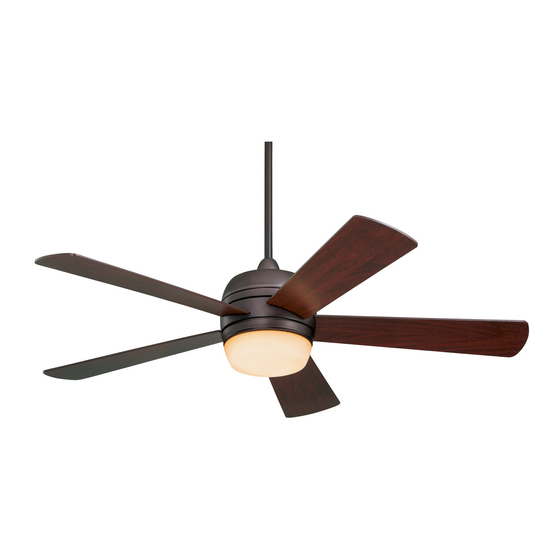
- Page 1 READ AND SAVE THESE INSTRUCTIONS ATOMICAL ™ 52” Damp Location Ceiling Fan Owner's Manual Model No. CF930BS02 CF930ORB02 CF930WW02 18.0 Net Weight: Lbs. Part No. F40BP73320002 Form No. BP7332-2 UL Model No.: CF930...
-
Page 2: Safety Instructions
WARNING: This product is designed to use only those parts supplied with this product and/or any accessories designated specifically for use with this product by Emerson Electric Co. Substitution of parts or accessories not designated for use with this product by Emerson Electric Co. could result in personal injury or property damage. -
Page 3: Unpacking Instructions
Two 60-watt (maximum) candelabra Emerson Electric Co. Substitution of base bulbs parts or accessories not designated for use with this product by Emerson Electric l. One loose parts bag containing: Co. could result in personal injury or 1. One clevis pin property damage. - Page 4 A. FAN MOTOR ASSEMBLY B. COUPLING COVER C. CEILING COVER E. LOWER K. 60-WATT HOUSING D. FAN BLADES CANDELABRA BULBS F. LIGHT KIT ASSEMBLY G. HANGER BRACKET H. HANGER BALL/ 4.5" DOWNROD ASSEMBLY I. LOWER GLASS J. FAN/LIGHT REMOTE CONTROL L.
-
Page 5: Electrical Requirements
IMPORTANT: Your ceiling fan will not General function properly, Your Emerson ceiling fan comes supplied damaged, if used with any wall dimmer with a Fan/Light Remote Control which switch or control other than the consists of a remote control (transmitter) - Page 6 2. Loosen setscrew in motor coupling if 3. While pulling up on the downrod, necessary. Separate, untwist and securely tighten the two setscrews in unkink the three 80” motor leads. Route the motor coupling (Figure 3). the motor lead wires through the NOTE: The setscrews must be properly downrod.
- Page 7 5. Reinstall the hanger ball (Figure 4) on the PARTIALLY ASSEMBLED downrod as follows. Route the motor leads through the downrod. Position the pin through the two holes in the downrod and align the ball so the pin is captured in SOLID the groove in the top of the hanger ball.
-
Page 8: Your Ceiling Fan How To Hang
NOTE: Make sure wires are not pinched How to Hang between fan motor assembly and lower Your Ceiling Fan housing. 10. Connect the black wire of the light kit WARNING assembly to the blue wire of the fan motor assembly using one wire The fan must be hung with at least 7' of connector (supplied). -
Page 9: How To Wire Your Ceiling Fan
How to Wire WARNING Your Ceiling Fan Hanger bracket must seat firmly against outlet box. If the outlet box is recessed, If you feel that you do not have enough remove wall board until bracket contacts electrical wiring knowledge box. If bracket and/or outlet box are not experience, have your fan installed by a securely attached, the fan could wobble licensed electrician. - Page 10 e. Securely connect the fan motor black WARNING wire to the receiver red (TO MOTOR L). Check to see that all connections are f. Securely connect the fan motor blue tight, including ground, and that no bare wire to the receiver blue (FOR LIGHT) wire is visible at the wire connectors, wire.
- Page 11 6. Screw in two 60-watt (maximum) 3. Screw the two 1-1/4” threaded studs candelabra base bulbs (supplied) in (supplied) into the tapped holes in the the light kit assembly sockets (Figure hanger bracket (Figure 13). 4. Lift the ceiling cover up to the threaded studs and turn until the studs protrude through the holes in the ceiling cover LIGHT KIT ASSEMBLY...
-
Page 12: Remote Control Procedures
Preset Memory Feature 1. Slide the five switch levers in the remote Your Emerson receiver is equipped with a control (transmitter) to your choice of preset memory feature. If the AC supply to ON (up) or down positions. Use a ball-... -
Page 13: Operation Of Remote Control
Installation of Storage Bracket TO INSTALL COVER A storage bracket is provided for holding BRACKET TO WALL: SLIDE THE COVER UP your remote control when not in use WALL TO EXPOSE THE (Figure 19). If you desire to use the BRACKET SCREW HOLES FOR bracket, install it on a wall that is away... -
Page 14: Maintenance
Emerson Electric Co. Substitution of parts or accessories not designated for use with this product by Emerson Electric Co. could result in personal injury or property damage. UL Model No.: CF930... - Page 15 WARNING: FOR YOUR OWN SAFETY TURN OFF POWER AT FUSE BOX OR CIRCUIT BREAKER BEFORE TROUBLE SHOOTING YOUR FAN. Trouble Shooting Ceiling Fan TROUBLE PROBABLE CAUSE SUGGESTED REMEDY 1. Fuse or circuit breaker 1. Check main and branch 1. Fan will not blown.
-
Page 16: How To Order Repair Parts
Repair Parts Before discarding packaging material, be certain all parts have been removed. HOW TO ORDER REPAIR PARTS WHEN ORDERING REPAIR PARTS, ALWAYS GIVE THE FOLLOWING INFORMATION: • PART NUMBER • PART DESCRIPTION • NAME OF ITEM • MODEL NUMBER The model number of your Fan will be found on a label attached to the top housing. - Page 17 Repair Parts Listing Part Numbers Model No. Model No. Model No. Description CF930BS02 CF930ORB02 CF930WW02 Hanger Pack, Consisting of: 761655-17 761655-32 761655 Hanger Bracket Assembly (1) — — — Hanger Ball (1) — — — Downrod (1) — — —...
-
Page 18: Instruction To The User
INSTRUCTION TO THE USER (if device contains a digital device) This equipment has been tested and found to comply with the limits for a Class B digital device, pursuant to part 15 of the FCC Rules. These limits are designed to provide reasonable protection against harmful interference in a residential installation. -
Page 19: Limited Warranty
If repair of the motor or blades is not practical or possible within a reasonable time and no replacement can be provided, Emerson Electric Co. will refund the actual purchase price of your fan. We will ship the repaired product or replacement to you at no charge, but you are responsible for all costs or removal, reinstallation and shipping of the product to Emerson Electric Co. - Page 20 Air Comfort Products DIVISION OF EMERSON ELECTRIC CO. 8100 W. Florissant • St. Louis, MO 63136 Part No. F40BP73320002 Printed in China 09/10 Form No. BP7332-2 UL Model No.: CF930...