Panasonic DP-3510 Service Manual
Digital imaging system
Hide thumbs
Also See for DP-3510:
- Operating instructions manual (168 pages) ,
- Information sheet (12 pages) ,
- Service handbook (12 pages)
Table of Contents
This service information is designed for experienced repair technicians only and is not intended for use by the general public.
It does not contain warnings or cautions to advise non-technical individuals of potential dangers in attempting to service a product.
Products powered by electricity should be serviced or repaired only by experienced professional technicians. Any attempt to service
or repair the product or products dealt within this service information by anyone else could result in serious injury or death.
Digital Imaging Systems
DP-3510/4510/6010
DP-3520/4520/6020
DP-3530/4530/6030
WARNING
© 2006 Panasonic Communications Co., Ltd.
All rights reserved. Unauthorized copying and distribution is
a violation of law. Published in Japan.
Order Number: MGCS041001C0
[ Version 5.2 ]
H21
Table of Contents
Troubleshooting

Related Manuals for Panasonic DP-3510


Summary of Contents for Panasonic DP-3510
- Page 1 Products powered by electricity should be serviced or repaired only by experienced professional technicians. Any attempt to service or repair the product or products dealt within this service information by anyone else could result in serious injury or death. © 2006 Panasonic Communications Co., Ltd. All rights reserved. Unauthorized copying and distribution is...
- Page 2 URL: http://www.senju-m.co.jp) is recommended when repairing PbF PCBs. The contents of this Service Manual and the Specifications are subject to change without notice. Panasonic Communications Co., Ltd. reserves the right to make improvements in the product design without reservation and without notice. Published in Japan.
-
Page 3: Important Notice
4. Unplug the AC Power Cord to shut the power Off completely. * The specifications are subject to change without notice. Panasonic Communications Co., Ltd. reserves the right to make improvements in the product design without reservation and without notice. -
Page 4
-
Page 5: For Your Safety
Precautions For Your Safety To prevent severe injury and loss of life, read this section carefully before servicing the Panasonic machine to ensure proper and safe operation of your machine. Please ensure that the machine is installed near a wall outlet and is easily accessible. -
Page 6: Operating Safeguards
Once a month, unplug the machine and check the power cord for the following. If you notice any unusual condition, contact the authorized Panasonic dealer The power cord is plugged firmly into the receptacle. The plug is not excessively heated, rusted, or bent. - Page 7 CAUTION Operating Safeguards Do not place a magnet near the safety switch of the machine. A magnet can activate the machine accidentally, resulting in injuries. Do not use a highly flammable spray or solvent near the machine. It can cause fire. When copying a thick document, do not use excessive force to press it against the scanning glass.
-
Page 8: Table Of Contents
8.3. Service Notes for "Firmware Update" 3.5. Resetting the P/M for PCL or PS Option Installation (Preventive Maintenance) Counter ..129 (For DP-3510/4510/6010) ....299 3.6. Updating the Firmware......131 8.4. Installing the Printer Controller Module 3.7. Copy Quality Adjustment for GDI-IPX/SPX (DA-GC601) Procedure (Order)........ - Page 9 Table of Contents 8.14. Installing the Fax Communication 9.3. Network Layer ........435 Board (DA-FG600)........323 9.4. Transport Layer ........439 8.15. Installing the Hard Disk Drive Unit 9.5. Upper Layer ......... 441 (DA-HD60) ..........332 9.6. SMTP 8.16. Installing the Accounting Software (Simple Mail Transfer Protocol)....
-
Page 10: Specifications Table
DP-3510/3520/3530/4510/4520/4530/6010/6020/6030 1 Specifications Table 1.1. Copy Function Description Items Remarks DP-3510/ DP-4510/ DP-6010/ 3520/3530 4520/4530 6020/6030 Basic Specifications 1 Type Console 2 Platen Fixed 3 Original Position Left 4 Recording Paper Path Center 5 Face Up / Face Down Face Down... - Page 11 DP-3510/3520/3530/4510/4520/4530/6010/6020/6030 Description Items Remarks DP-3510/ DP-4510/ DP-6010/ 3520/3530 4520/4530 6020/6030 17 Maximum Tray Capacities Front loading universal Paper Tray Paper Tray 1,550 sheets x 1 Capacity 550 sheets x 1 USA and Canada Auto Size Setting Yes (2nd Tray only)
- Page 12 DP-3510/3520/3530/4510/4520/4530/6010/6020/6030 Description Items Remarks DP-3510/ DP-4510/ DP-6010/ 3520/3530 4520/4530 6020/6030 28 Occupancy Area 47.2 x 29.6 in Includes Bypass Paper (W x D) (1,200 x 753 mm) Tray. 251 lb 258 lb 258 lb Main Unit only, (114 kg) (117 kg) (117 kg) without i-ADF.
- Page 13 DP-3510/3520/3530/4510/4520/4530/6010/6020/6030 Description Items Remarks DP-3510/ DP-4510/ DP-6010/ 3520/3530 4520/4530 6020/6030 8 Electronic Sorting Board Standard (32 MB) CODEC + 32 MB memory Optional Image Memory 1 (16 MB) Only one of three available Optional Image Memory 2 types can be installed.
- Page 14 DP-3510/3520/3530/4510/4520/4530/6010/6020/6030 Description Items Remarks DP-3510/ DP-4510/ DP-6010/ 3520/3530 4520/4530 6020/6030 Centering Mode Mirror Mode Others (Inverting ADF & ADU) LDR → LTR x 2 2-Page Copy Mode (A3 → A4 x 2, B4 → B5 x 2) 2 in 1...
- Page 15 DP-3510/3520/3530/4510/4520/4530/6010/6020/6030 Description Items Remarks DP-3510/ DP-4510/ DP-6010/ 3520/3530 4520/4530 6020/6030 Electronic Counter Digital Sky Shot Mode Check / Slip Mode 3 Control Panel Display Wide Touch Panel LCD GREEN : Scanning / Status Lamp Printing : Alarm / Warning Original Size...
- Page 16 DP-3510/3520/3530/4510/4520/4530/6010/6020/6030 Description Items Remarks DP-3510/ DP-4510/ DP-6010/ 3520/3530 4520/4530 6020/6030 Toner Waste Container Full Add Paper (No Paper) Add Paper (Under 50 Sheets) Paper Jam Indication Paper Jam Location Service Alert Call User Error Machine Error History of Jam Errors...
- Page 17 DP-3510/3520/3530/4510/4520/4530/6010/6020/6030 Description Items Remarks DP-3510/ DP-4510/ DP-6010/ 3520/3530 4520/4530 6020/6030 ADU Copy Productivity When ejecting to Outer (LTR / A4) Tray Transport Method Stackless 1→2 1 copy Throughput 5 copies 10 copies PM Cycle 1 PM Cycle Major PM 120K...
-
Page 18: Fax, Printer, Network Scanner And Internet Fax Functions
DP-3510/3520/3530/4510/4520/4530/6010/6020/6030 1.2. Fax, Printer, Network Scanner and Internet Fax Functions 1.2.1. Fax Function Description Items Remarks DP-3510/ DP-4510/ DP-6010/ 3520/3530 4520/4530 6020/6030 Main Specifications 1 Compatibility ITU-T Std. & Non-Std. (PCC) 2 PSTN Line Port 1-Line Only 3 Leased Line Port 4 V.24 Line Port... - Page 19 DP-3510/3520/3530/4510/4520/4530/6010/6020/6030 Description Items Remarks DP-3510/ DP-4510/ DP-6010/ 3520/3530 4520/4530 6020/6030 8 ADF Capacity 70 sheets Face-Up, feed from top page 9 Collation Stack Face Down Printer Mechanism 1 Recording Method 35 ppm 45 ppm 60 ppm 2 Recording Speed Horizontal)
- Page 20 DP-3510/3520/3530/4510/4520/4530/6010/6020/6030 Description Items Remarks DP-3510/ DP-4510/ DP-6010/ 3520/3530 4520/4530 6020/6030 Max. Station Name Characters Direct Dialing Voice mode (Monitor Dialing) 9 Automatic Redialing 10 Manual Redialing 11 Line Monitor Speaker Available for Line-1 only 12 Chain Dialing (Hybrid Dial) In Monitor Dialing mode only...
- Page 21 DP-3510/3520/3530/4510/4520/4530/6010/6020/6030 Description Items Remarks DP-3510/ DP-4510/ DP-6010/ 3520/3530 4520/4530 6020/6030 Page End Approx. 0.51 in (13 4 Overlap Printing 5 Receive to Memory Distinctive Ring Detector (DRD) 90 Degree Rotation Reception 8 Duplex Printing Polling 1 Polling 2 Turnaround Polling 3 Multi-Station Polling Max.
- Page 22 DP-3510/3520/3530/4510/4520/4530/6010/6020/6030 Description Items Remarks DP-3510/ DP-4510/ DP-6010/ 3520/3530 4520/4530 6020/6030 Identifications 1 Logo 25 Characters 2 Multiple Logo 3 Character ID 16 Characters 4 Numeric ID 20 Digits Special Communications 1 Password XMT / RCV 2 Selective Reception TSI Check...
-
Page 23: Printer Function
DP-3510/3520/3530/4510/4520/4530/6010/6020/6030 1.2.2. Printer Function Description Items Remarks DP-3510/ DP-4510/ DP-6010/ 3520/3530 4520/4530 6020/6030 Interface 1 Centronics Parallel I/F Centronics Parallel Interface IEEE-1284 Compliant Ethernet 10Base-T/ 2 LAN (Network) 100Base-TX 3 USB Port 4 IEEE-1394 Printer Function Ledger, Legal, Letter, Invoice, A3, A4,... -
Page 24: Network Scanner Function
DP-3510/3520/3530/4510/4520/4530/6010/6020/6030 1.2.3. Network Scanner Function Description Items Remarks DP-3510/ DP-4510/ DP-6010/ 3520/3530 4520/4530 6020/6030 Interface 1 Centronics Parallel I/F IEEE-1284 Compliant Ethernet 10Base-T/ 2 LAN (Network) 100Base-TX 3 USB Port 4 IEEE-1394 Firewire Network Scanning Function 1 Scanning Device CCD (i-ADF / Platen) - Page 25 DP-3510/3520/3530/4510/4520/4530/6010/6020/6030 1.2.4. Internet Fax Function Description Items Remarks DP-3510/ DP-4510/ DP-6010/ 3520/3530 4520/4530 6020/6030 Main Specifications Communication TCP / IP SMTP / MIME Protocols 2 Max. Modem Speed 3 Coding Scheme MH / MMR / JBIG PDF format is available for DP-3520/ 3530/4520/4530/6020/6030 only.
- Page 26 Emulation Kit 8 DHCP Client 9 LDAP Lightweight Directory Access Protocol 10 TIFF Viewer Selectable, PDMS / TIFF Viewer Certainty Comm. Journal Email from RCV side to Panasonic (w / Image) Internet FAX's only 1 Email Address Ver. 5.2 JAN 2006...
-
Page 27: System Combination
DP-3510/3520/3530/4510/4520/4530/6010/6020/6030 1.3. System Combination Inverting ADF (i-ADF) ADF PC Board Document Sensor Scanner Unit and Motor Panel Main PC Board PCL6 Fax Communication (PNL PC Board) (SC PC Board) Emulation Option Option PS/PCL6 Printer Emulation Option Network Parallel Port Scanner Option... -
Page 28: Options And Supplies List
Controller Module for PS/PCL6 Printer Controller Module for PCL6-IPX/ For DP-3520 / 4520 / 6020 DA-PC601 (For USA and Canada, can also be used for DP-3510 / 4510 / 6010 without IPX/ Multi Page Description Language DA-MC601 SPX) Controller Module for PS/PCL6-IPX/SPX... - Page 29 PCL6 is a Page Description Language of the Hewlett-Packard Company. PS/PS3 is a Page Description Language of the Adobe Systems Company. Supplies Part Name Part Number Remarks DQ-TU24D 24K for DP-3510/4510 DQ-TU35D 35K for DP-6010 Toner DQ-TU241G 24K for DP-3520/3530/4520/4530 DQ-TU351G...
-
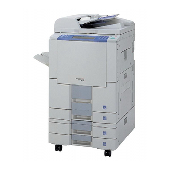
Page 30: External View
DP-3510/3520/3530/4510/4520/4530/6010/6020/6030 1.5. External View 1. Standard Configuration (For USA only) Product complies with DHHS Rules 21 CFR Subchapter J in effect at date of manufacture. Top View Manufacturer's name and address Factory ID 12.7 in 10.4 in 23.6 in (600 mm) - Page 31 DP-3510/3520/3530/4510/4520/4530/6010/6020/6030 3. Space Requirements With Options Copier + Exit Tray 3.9 in (100 mm) 3.9 in (100 mm) 23.6"(600 mm) 3.9 in (100 mm) 57.6 in (1463 mm) 12.7 in 10.4 in (265 mm) (322 mm) 19.9 in (505 mm) 3.9 in (100 mm)
- Page 32 A0001 ~ Y9999 = 100,000 ~ 329,976 units (Letters “I” and “O” are skipped) Model Number and Destination Code (Main Unit) 3-Digit number or alphanumeric representation (Except Letters “I” and “O”) For Example: = DP-3510-PU = DP-4510-PU = DP-6010-PU = DP-3520-PU = DP-4520-PU = DP-6020-PU...
-
Page 33: Control Panel
DP-3510/3520/3530/4510/4520/4530/6010/6020/6030 1.6. Control Panel DP-3510/3520/4510/4520/6010/6020 DP-3530/4530/6030 DP-6030 PRINT DATA ACTIVE STATUS Ver. 5.2 JAN 2006... -
Page 34: Fans And Motors
DP-3510/3520/3530/4510/4520/4530/6010/6020/6030 1.7. Fans and Motors ADF Paper Feed Motor ADF Feed Motor Scanning Motor Cooling Fan3 Corona Wire Cleaning Motor Ozone Fan Cooling Fan2 Dust Fan Cooling Fan1 Hopper Motor Main Motor Inverting Motor Drum Motor Suction Fan Cooling Fan... -
Page 35: Sensors
DP-3510/3520/3530/4510/4520/4530/6010/6020/6030 1.8. Sensors ADF Original ADF Exit Sensor Width Sensor1 ADF Original Sensor ADF Original Width Sensor2 ADF Cover Open Sensor ADF Original Length Sensor1 ADF Registration ADF Original Length Sensor2 Sensor1 ADF Registration Platen Cover (ADF) Angle Sensor Sensor3... -
Page 36: Clutches And Switches
DP-3510/3520/3530/4510/4520/4530/6010/6020/6030 1.9. Clutches and Switches ADF Inverting Roller Clutch2 ADF Inverting Roller Clutch1 ADF Paper Feed Roller Clutch ADF Registration Roller Clutch1 ADF Registration Roller Clutch2 ADF Exit Roller Clutch ADF Pinch Solenoid ADF Inverting Roller Solenoid Separator Solenoid Paper Exit Transportation... -
Page 37: Disassembly Instructions
DP-3510/3520/3530/4510/4520/4530/6010/6020/6030 2 Disassembly Instructions 2.1. General Disassembly Pertinent Disassembly Instruction sections are shown below. Scanner Unit i-ADF 2.2.4. 2.2.3. Control Panel Unit 2.2.12. 2.2.5. Sheet Bypass Unit Paper Exit Transportation 2.2.14. 2.2.15. Drive Unit Fuser Unit 2.2.17. 2.2.11. Paper Feed Module 2.2.13. -
Page 38: Disassembly Instructions
DP-3510/3520/3530/4510/4520/4530/6010/6020/6030 2.2. Disassembly Instructions 2.2.1. Filters (1) Turn the Power Switches to the OFF position. (2) Disconnect the AC Power Cord (4911). (3) Open the Right Cover. (4) Remove 3 Screws (H8). (5) Remove the Right Side Rear Cover (117). -
Page 39
DP-3510/3520/3530/4510/4520/4530/6010/6020/6030 (9) Remove the Ozone Filter 2 Cover (106). (10) Remove the Ozone Filter 2 (107).
(11) Remove 9 Screws (H8). (12) Remove the Rear Upper Cover (110). (13) Remove the Ozone Filter 4 (4226). - Page 40 DP-3510/3520/3530/4510/4520/4530/6010/6020/6030 (14) Remove 2 Screws (21). (15) Pull the Rear Frame 2 (3910) and remove the Ozone Filter 4 (4226). Note: To prevent Rear Frame 2 from warping, do not pull hard on it. Ver. 5.2 JAN 2006...
- Page 41 DP-3510/3520/3530/4510/4520/4530/6010/6020/6030 2.2.2. Toner Waste Container (1) Open the Right Cover. (2) Remove 3 Screws (H8). (3) Remove the Right Side Rear Cover (117). (4) Remove the Toner Waste Container (4108). Ver. 5.2 JAN 2006...
- Page 42 DP-3510/3520/3530/4510/4520/4530/6010/6020/6030 2.2.3. Inverting-Automatic Document Feeder (i-ADF) Unit (1) Lift up the Original Tray Assembly. (2) Clean the Exit Roller (814). (3) Open the ADF Cover. (4) Clean the Pickup Roller (511), Paper Feed Roller (508), Separation Roller (610) and Registration Roller 1 (817) with a soft cloth, saturated with isopropyl alcohol.
- Page 43 DP-3510/3520/3530/4510/4520/4530/6010/6020/6030 (6) Remove the Paper Feed Roller Shaft (505) Assembly in the arrow direction. (7) Remove the Paper Feed Roller (508). (8) Move the Pickup Bracket. (9) Remove 2 Snap Rings (H7). (10) Remove the Pickup Roller Shaft (510). (11) Remove the Pickup Roller (511).
- Page 44 DP-3510/3520/3530/4510/4520/4530/6010/6020/6030 (12) Remove 3 Screws (J9). (13) Remove the Lower Opening and Shutting Guide 1 (601). (14) Remove the Separation Roller Assembly. (15) Remove the Snap Ring (H6). Note: When reinstalling, make sure that the Snap Ring is installed properly as illustrated.
- Page 45 DP-3510/3520/3530/4510/4520/4530/6010/6020/6030 (16) Remove the Separation Roller Shaft (607). (17) Remove the Separation Roller (610). Note: When reassembling the Separation Roller, make sure that the Yellow Tooler's Die on the side of the roller is positioned as illustrated (facing the Front Frame).
- Page 46 DP-3510/3520/3530/4510/4520/4530/6010/6020/6030 (24) Remove 1 Screw (J2). (25) Loosen 3 Screws (H8). (26) Lift up the Original Tray Assembly. (27) Remove the ADF Rear Cover (627). (28) Remove 1 Screw (21). (29) Remove the Front ADF Cover Bracket (529). (30) Release the ADF Cover Arm (624).
- Page 47 DP-3510/3520/3530/4510/4520/4530/6010/6020/6030 (32) Remove 1 Screw (21). (33) Remove the Registration Guide 2 (721). (34) Clean the Registration Roller 2 (818). (35) Remove the Snap Ring (G6). (36) Remove the D8 Bearing (822). (37) Remove 2 Snap Rings (G6). (38) Remove the Clutch 1 (801).
- Page 48 DP-3510/3520/3530/4510/4520/4530/6010/6020/6030 (40) Remove the Registration Roller 2 (818). (41) Remove 2 Registration Guide Sheets 1 (1119) and 2 Registration Guide Sheets 2 (1120). Caution: Do not remove the 3 indicated Screws. Note: When reinstalling the Registration Guide Sheet 1 and 2, make sure that the Sheets are placed on the marks as illustrated.
- Page 49 DP-3510/3520/3530/4510/4520/4530/6010/6020/6030 (42) Open the Lower Opening and Shutting Guide Assembly. (43) Lift up the Original Tray Assembly. (44) Nudge the Inverting Guide Assembly towards the right side to open it. (45) Remove 2 Screws (21). (46) Remove the Inverting Guide Assembly.
-
Page 50: Scanner Unit
DP-3510/3520/3530/4510/4520/4530/6010/6020/6030 2.2.4. Scanner Unit 2.2.4.1. Scanner Lamp, CCD Assembly (1) Move the Scanning Lamp to the position where it can be replaced. (See Sect. 5.1.7. F8-00.) (2) Remove 2 Screws (H8). (3) Remove the Right Platen Cover (112). (4) Remove the Glass Assembly (120). -
Page 51
DP-3510/3520/3530/4510/4520/4530/6010/6020/6030
(8) Disconnect 2 Harnesses on the Inverter PC Board (1209). (9) Remove 2 Screws (F10). (10) Remove the Inverter PC Board (1209). (11) Remove the Scanning Lamp (1228). Note: Ensure that the Scanning Lamp Harness is reinstalled properly as illustrated. - Page 52 DP-3510/3520/3530/4510/4520/4530/6010/6020/6030 (12) Remove 5 Screws (21). (13) Remove the CCD Cover (1213). (14) Disconnect 2 Harnesses on the CCD PC Board (CN850 and CN851). Important: Before proceeding, make a note of the position of the alignment pointer. If the CCD is not reinstalled at the same position, it will affect the copy quality.
- Page 53 DP-3510/3520/3530/4510/4520/4530/6010/6020/6030 (17) Remove 2 Screws (20). (18) Disconnect 2 Harnesses on the Sensors. (19) Remove 2 Multi Beam Sensors (1309). (20) Remove 1 Screw (20). (21) Disconnect the Harness on the Sensor. (22) Remove the Multi Beam Sensor (1309). (23) Clean the Mirror 1 (1202) and Mirror 2 (1214).
- Page 54 DP-3510/3520/3530/4510/4520/4530/6010/6020/6030 2.2.4.2. Scanning Motor (1) Remove 9 Screws (H8). (2) Remove the Rear Upper Cover (110). (3) Remove 2 Screws (21). (4) Remove the Harness Clamp 2 (3501). (5) Disconnect the ADF Harness. (6) Open the ADF Unit. (7) Remove 2 Screws (P4).
- Page 55 DP-3510/3520/3530/4510/4520/4530/6010/6020/6030 (9) Remove 2 Screws (H8). (10) Remove the Left Platen Cover (111). (11) Remove 2 Screws (H8). (12) Remove the Right Platen Cover (112). (13) Remove 2 Screws (N6). (14) Remove 4 Screws (H8). (15) Remove the Rear Platen Cover (113).
-
Page 56: Control Panel Unit
DP-3510/3520/3530/4510/4520/4530/6010/6020/6030 2.2.5. Control Panel Unit (1) Open the Front Cover. (2) Swing the Hopper Unit in the direction of the arrow as illustrated. (3) Remove the Battery Holder. (4) Remove 7 Screws (21). (5) Remove the Lower Control Panel Cover (101). - Page 57 DP-3510/3520/3530/4510/4520/4530/6010/6020/6030 (6) Turn the Control Panel Unit upside down. (7) Disconnect 4 Harnesses on the PNL1 PC Board (CN220, CN221, CN222 and CN224). (8) Remove 1 Screw (21). (9) Disconnect 4 Harnesses on the PNL1 PC Board (CN223, CN225, CN229 and CN230).
- Page 58 DP-3510/3520/3530/4510/4520/4530/6010/6020/6030 (12) Disconnect the Harness on the PNL2 PC Board (CN251). (13) Remove 7 Screws (F10). (14) Remove the PNL2 PC Board (323). (15) Disconnect the Harness on the INV PC Board (CN2). (16) Remove 2 Screws (F10). (17) Remove the INV PC Board (329).
- Page 59 DP-3510/3520/3530/4510/4520/4530/6010/6020/6030 (22) Remove 4 Screws (F10). (23) Remove the PNL3 PC Board (313). (24) Remove 2 Screws (H4). (25) Remove 2 Screws (H4). (26) Remove the LCD Module (328). (27) Remove the Touch Panel (327). Note: Reinstall the Battery Holder after reassembling the Lower Control Panel Cover.
-
Page 60: Hopper Unit
DP-3510/3520/3530/4510/4520/4530/6010/6020/6030 2.2.6. Hopper Unit (1) Open the Front Cover. (See Sect. 2.2.5.) (2) Swing the Hopper Unit to the right side. (See Sect. 2.2.5.) (3) Rotate the Toner Bottle counter-clockwise and remove it. (4) Clean any toner residue from the Lower Hopper Cover (1411). - Page 61 DP-3510/3520/3530/4510/4520/4530/6010/6020/6030 (8) Remove 2 Screws (21). (9) Remove the Hopper Motor (1414). Ver. 5.2 JAN 2006...
-
Page 62: Developer Unit
DP-3510/3520/3530/4510/4520/4530/6010/6020/6030 2.2.7. Developer Unit (1) Open the Front Cover. (See Sect. 2.2.5.) (2) Swing the Hopper Unit to the right side. (See Sect. 2.2.5.) (3) Remove 1 Screw (J9). (4) Remove the Connector Cover (3930). (5) Disconnect the Harness. (6) Pull the Developer Release Lever (3823) out and turn it clockwise. -
Page 63
DP-3510/3520/3530/4510/4520/4530/6010/6020/6030 (10) Release 3 Latch Hooks and remove the Upper Developer Cover (1601).
(11) Install the Developer Exchange Knob (1405). (12) Turn the Developer Unit upside down over a suitable container and dump the used Developer and Toner by rotating the Knob. - Page 64 DP-3510/3520/3530/4510/4520/4530/6010/6020/6030 (15) Clean the Developer Unit (1632) with a dry soft cloth. Caution: Clean the Developer and Toner residue from the encircled areas thoroughly as shown in the illustrations. If not properly cleaned, problems related to static charge may occur.
-
Page 65: Drum Unit
DP-3510/3520/3530/4510/4520/4530/6010/6020/6030 2.2.8. Drum Unit (1) Open the Front Cover. (See Sect. 2.2.5.) (2) Swing the Hopper Unit to the right side. (See Sect. 2.2.5.) (3) Pull the Developer Release Lever (3823) out and turn it clockwise. (4) Turn the Lifting Lever (2327) counter-clockwise. - Page 66 DP-3510/3520/3530/4510/4520/4530/6010/6020/6030 Caution: The OPC Drum is sensitive to light. To prevent optical exposure problems, do not expose the OPC Drum to direct sunlight or bright light (even if it is a 1000-Lux fluorescent lamp). (7) Cover the Drum with 2 sheets of white paper as illustrated.
- Page 67 DP-3510/3520/3530/4510/4520/4530/6010/6020/6030 (12) Release 2 Latch Hooks and remove the Frame Cover (1805). (13) Remove 4 Screws (21). (14) Remove the Front Fixation Plate (1822). (15) Turn the Front Drum Bushing (1820) counter-clockwise and remove it. (16) Remove 4 Screws (21).
- Page 68 DP-3510/3520/3530/4510/4520/4530/6010/6020/6030 (18) Turn the Rear Drum Bushing (1842) clockwise and remove it. (19) Remove the OPC Drum (1811). (20) Remove the Blade Pressure Spring (1807). (21) Remove 1 Screw (20). (22) Remove the Cleaning Blade (1847) Assembly. Ver. 5.2 JAN 2006...
-
Page 69
DP-3510/3520/3530/4510/4520/4530/6010/6020/6030 Note: When reinstalling the Cleaning Blade Assembly, make sure that the Hooks are properly attached. (23) Release 4 Latch Hooks and remove the Front and Rear Cleaning Felt (1849, 1848) Assemblies.
(24) Clean the Density Sensor (CDS PC Board) (1846) with a dry cloth. - Page 70 DP-3510/3520/3530/4510/4520/4530/6010/6020/6030 (28) Clean the Corona Grid (1919) with a soft cloth, saturated with isopropyl alcohol (29) Remove the Front and Rear Block Sheets (1911 and 1920). (30) Remove the Corona Wire (1915) and the Tension Spring (1914). (31) Remove the Cleaning Base 3 (1918).
- Page 71 DP-3510/3520/3530/4510/4520/4530/6010/6020/6030 (32) Clean the Corona Case (1906) with a soft cloth or a cotton swab, saturated with isopropyl alcohol. Ver. 5.2 JAN 2006...
- Page 72 DP-3510/3520/3530/4510/4520/4530/6010/6020/6030 2.2.9. Auto Duplex Unit (ADU) (1) Open the Front Cover. (See Sect. 2.2.5.) (2) Swing the Hopper Unit to the right side. (See Sect. 2.2.5.) (3) Turn the Lifting Lever (2327) counter-clockwise. (4) Pull the ADU Unit out. (5) Clean the Exit Rollers A and B and C (2520, 2521, 2522).
- Page 73 DP-3510/3520/3530/4510/4520/4530/6010/6020/6030 (8) Clean the Intermediate Roller (2403). (9) Clean the Registration Roller (2430). (10) Pull out the 1st Paper Tray. (11) Remove 1 Screw (25). (12) Remove the Right Lock Plate (3810). (13) Remove 1 Screw (21). (14) Remove the Left Lock Plate (3812).
- Page 74 DP-3510/3520/3530/4510/4520/4530/6010/6020/6030 (15) Remove the ADU Unit (2351). (16) Remove 1 Screw (24). (17) Remove the Lifting Lever (2327). (18) Remove 1 Screw (23). (19) Remove the Registration Release Knob (2328). (20) Remove 3 Screws (21). (21) Remove the Inner Cover (2332).
- Page 75 DP-3510/3520/3530/4510/4520/4530/6010/6020/6030 (27) Remove the Registration Gear (2344). (28) Remove 2 Snap Rings (K9). (29) Remove the 2 Bearings (822). (30) Remove 2 Screws (F10). (31) Remove 2 E-Rings (J7). (32) Remove the Intermediate Roller Gear (2621). (33) Remove 2 Bearings (2603).
- Page 76 DP-3510/3520/3530/4510/4520/4530/6010/6020/6030 (38) Remove the Registration Roller (2430). (39) Remove the Intermediate Roller (2403). Ver. 5.2 JAN 2006...
- Page 77 DP-3510/3520/3530/4510/4520/4530/6010/6020/6030 2.2.10. Corona Unit 2 (1) Open the Front Cover. (See Sect. 2.2.5.) (2) Swing the Hopper Unit to the right side. (See Sect. 2.2.5.) (3) Pull out the ADU Unit. (See Sect. 2.2.9.) (4) Remove the Corona Unit 2 (2352).
- Page 78 DP-3510/3520/3530/4510/4520/4530/6010/6020/6030 (12) Disconnect the Harness. (13) Pull out the LED PC Board (2343). (14) Remove the LED Knob (2319). Ver. 5.2 JAN 2006...
-
Page 79: Fuser Unit
Exit Guide 7 (8126). (5) Remove 2 Screws (N3). (6) Remove the Fuser Cover (121). (7a) Disconnect 4 Harnesses. (For DP-4510/4520/ 4530/6010/6020/6030) (7b) Disconnect 5 Harnesses. (For DP-3510/3520/ 3530) (8) Remove 1 Screw (25). (9) Remove the Fuser Unit (2035). Ver. 5.2... - Page 80 DP-3510/3520/3530/4510/4520/4530/6010/6020/6030 (10) Release the Harnesses from Hooks. (11) Remove 1 Screw (L6). (12) Remove the Solenoid (2012) Assembly. (13) Remove 1 Screw (K2). (14) Remove the Solenoid (2012). (15) Remove 2 Screws (K1). (16) Remove the Cleaning Web Unit. Ver. 5.2...
- Page 81 DP-3510/3520/3530/4510/4520/4530/6010/6020/6030 (17) Remove 1 Screw (21). (18) Remove the Rear Cleaning Web Frame (2002). (19) Remove the Cleaning Web Roller (2007) (Red). (20) Remove the Cleaning Web (2003) (White). Note: When reinstalling, make sure that the Cleaning Web is spread out.
-
Page 82
DP-3510/3520/3530/4510/4520/4530/6010/6020/6030
Follow steps (27) ~ (32) below. [For DP-3510/4510/6010, skip to steps (33) ~ (36)] (27) Remove 2 Snap Rings (H6). (28) Remove the Upper Paper Exit Guide (2223). (29) Remove 2 Screws (36). (30) Remove the Upper Separator Bracket (2120). - Page 83 DP-3510/3520/3530/4510/4520/4530/6010/6020/6030 (35) Remove 5 Tension Springs (2219). (36) Remove 5 Upper Separators (2227). (37) Remove 1 Screws (36). (38) Remove 1 Screw (K2). (39) Remove the Rear Fuser Cover (2031). (40) Remove 2 Screws (16). (41) Remove 2 Fuser Lamps (2027, 2028).
- Page 84 DP-3510/3520/3530/4510/4520/4530/6010/6020/6030 (42) Release the Harness from Hooks. (43) Remove 1 Screw (16). (44) Loosen 1 Screw inside of the Jam Release Knob by turning clockwise. (45) Remove the Jam Release Knob (2022). Note: The Jam Release Knob and Screw are assembled.
- Page 85 DP-3510/3520/3530/4510/4520/4530/6010/6020/6030 (54) Remove 1 Screw (B2). (55) Remove the Upper Front Guide (2102). (56) Remove 2 Screws (36). (57) Remove the Lower Front Guide (2113). (58) Remove 2 Screws (K4). (59) Remove 1 Screw (K2). (60) Remove the Upper Fuser Bracket (2115).
- Page 86 DP-3510/3520/3530/4510/4520/4530/6010/6020/6030 (63) Remove the Pressure Roller (2205). (64) Remove 2 Pressure Roller Bearings (2204). Note: Before removing, note the position and/or direction of the Pressure Roller Bearings for proper reinstallation. Ver. 5.2 JAN 2006...
- Page 87 DP-3510/3520/3530/4510/4520/4530/6010/6020/6030 2.2.12. LSU (1) Open the Sheet Bypass. (2) Open the Right Cover. (3) Remove 2 Screws (21). (4) Remove the LSU Cover (115). (5) Remove the Right Platen Cover. (See Sect. 2.2.4.) (6) Remove 2 Screws (20). (7) Remove the LSU Shield Bracket (4009).
- Page 88 DP-3510/3520/3530/4510/4520/4530/6010/6020/6030 (10) Remove 3 Screws (L1). (11) Remove the LSU (4030). (12) Turn the LSU upside down. (13) Clean the LSU Glass with a soft cloth, saturated with isopropyl alcohol. Ver. 5.2 JAN 2006...
-
Page 89: Paper Feed Module
DP-3510/3520/3530/4510/4520/4530/6010/6020/6030 2.2.13. Paper Feed Module (1) Open the Right Cover (2908). (2) Clean the Intermediate Rollers (3005, 3010) with a soft cloth, saturated with isopropyl alcohol. (3) Remove 1 Screw (J4). (4) Remove the Right Cover (2908). (5) Push the Pin and remove the Right Cover (2908). - Page 90 DP-3510/3520/3530/4510/4520/4530/6010/6020/6030 (9) Remove the 1st Paper Feed Module. (10) Remove 1 Screw (21). (11) Remove the Front Feed Guide (3122). (12) Remove the Bushing 2 (208) and One Way Clutch (3205). (13) Lift the Reverse Roller (3219) Assembly and remove the Feed Roller (3204).
- Page 91 DP-3510/3520/3530/4510/4520/4530/6010/6020/6030 (14) Remove the Snap Ring (H7). (15) Remove the Pickup Roller (3211). Note: When reinstalling, make sure that the Latches and the Notches are aligned as illustrated. (16) Remove the Snap Ring (H6). (17) Remove the Reverse Roller (3219).
- Page 92 DP-3510/3520/3530/4510/4520/4530/6010/6020/6030 (18) Disconnect the Harness. (19) Remove 1 Screw (J4). (20) Remove the 2nd Paper Feed Module. Note: Follow the instructions for steps (10)~(17) of the 1st Paper Feed Module. (21) Remove the Snap Ring (G6). (22) Remove the 3 Intermediate Roller (3005, 3010) Assemblies.
-
Page 93: Sheet Bypass Unit
DP-3510/3520/3530/4510/4520/4530/6010/6020/6030 2.2.14. Sheet Bypass Unit (1) Remove the LSU Cover. (See Sect. 2.2.12.) (2) Clean the Front and Rear Pickup Rollers (4603, 4611). (3) Pull out the ADU (2351). (See Sect. 2.2.9.) Note: Ref. No. 2351 does not include all individual parts. - Page 94 DP-3510/3520/3530/4510/4520/4530/6010/6020/6030 (12) Remove 4 Screws (25). (13) Remove the Feed Cover (4638) Assembly. (14) Remove the Snap Ring (H6). (15) Remove the Paper Feed Roller (4608). (16) Remove the Feed Roller (4612). Ver. 5.2 JAN 2006...
-
Page 95: Paper Exit Transportation
DP-3510/3520/3530/4510/4520/4530/6010/6020/6030 2.2.15. Paper Exit Transportation (1) Open the Lower Exit Cover (8011). (2) Remove 2 Screws (H8). (3) Remove the Exit Cover 3 (8003). (4) Open the Front Cover. (See Sect. 2.2.5.) (5) Open the Paper Exit Cover. (See Sect. 2.2.11.) (6) Remove 4 Screws (25). - Page 96 DP-3510/3520/3530/4510/4520/4530/6010/6020/6030 2.2.16. PC Boards (1) Remove the Rear Upper Plate. (See Sect. 2.2.4.2.) (2) Disconnect All Harnesses on the DRV PC Board. (3) Remove 7 Screws (21). (4) Remove the DRV PC Board (8601). (5) Remove 4 Screws (21). (6) Remove the SC Cover Bracket (3303).
- Page 97 DP-3510/3520/3530/4510/4520/4530/6010/6020/6030 (8) Remove 6 Screws (21). (9) Remove the SC PC Board (8401). (10) Remove 2 Screws. (11) Remove the PRT PC Board (8402). (12) Remove 5 Screws (H8). (13) Remove 1 Screw (M5). (14) Remove the Rear Lower Cover (108).
- Page 98 DP-3510/3520/3530/4510/4520/4530/6010/6020/6030 (17) Remove 5 Screws (21). (18) Remove the SPC PC Board (8501). (19) Remove 3 Screws (21). (20) Remove NFL PC Board (8603) Assembly. (21) Disconnect 2 Harnesses on the NFL PC Board (CN132 and CN133). (22) Remove 2 Screws (21).
- Page 99 DP-3510/3520/3530/4510/4520/4530/6010/6020/6030 (25) Remove 4 Screws (21). (26) Remove the Paper Exit Motor (8127) Assembly. (27) Disconnect 3 Harnesses. (28) Open the Front Cover. (See Sect. 2.2.5.) (29) Pull out 1st Paper Tray. (30) Remove 2 Screws (21). (31) Remove the LVPS Cover (203).
- Page 100 DP-3510/3520/3530/4510/4520/4530/6010/6020/6030 (34) Disconnect the All Harnesses on the DC PC Board (CN141, CN142, CN143, CN144 and CN145). (35) Remove 2 Screws (21). (36) Remove the DC PC Board (8701). (37) Remove 7 Screws (21). (38) Remove the Heat Sink (3311).
- Page 101 DP-3510/3520/3530/4510/4520/4530/6010/6020/6030 (43) Pull out the ACD PC Board (8704) Assembly. (44) Disconnect the Harness on the ACD PC Board (CN102). (45) Disconnect 2 Harnesses on the ACD PC Board (CN103 and CN104). (46) Remove 6 Screws (21). (47) Remove the ACD PC Board (8704).
-
Page 102: Drive Unit
DP-3510/3520/3530/4510/4520/4530/6010/6020/6030 2.2.17. Drive Unit (1) Remove the Toner Waste Container. (See Sect. 2.2.2.) (2) Remove the Rear Upper Plate. (See Sect. 2.2.4.2.) (3) Remove the Rear Lower Plate and SC Cover Bracket. (See Sect. 2.2.16.) (4) Disconnect All Harnesses on the SC PC Board. - Page 103 DP-3510/3520/3530/4510/4520/4530/6010/6020/6030 (11) Remove 2 Screws (21). (12) Remove the Fan (4219) Assembly. (13) Remove 2 Screws (20). (14) Remove the Fan (4221) Assembly. (15) Remove 2 Screws (H8). (16) Remove the Rear Cover (9301). (17) Remove 4 Screws (21). (18) Remove the Rear Frame 2 (3910).
- Page 104 DP-3510/3520/3530/4510/4520/4530/6010/6020/6030 (19) Open the Front Cover. (See Sect. 2.2.5.) (20) Move the Hopper Unit. (See Sect. 2.2.5.) (21) Pull out the ADU (2351) and Drum Unit (1852). Note: Ref. No. 2351 and 1852 do not include all individual parts. (22) Remove the Fuser Cover. (See Sect. 2.2.11.) (23) Remove 1 Screw (24).
- Page 105 DP-3510/3520/3530/4510/4520/4530/6010/6020/6030 (29) Remove the Pin (2743). (30) Remove 2 Screws (21). (31) Move the Harness Bracket (3525). (32) Disconnect the Harness on the Toner Waste Sensor. (33) Disconnect the Harness on the HVPS (CN101). (34) Lift up the Toner Waste Pipe 2 (4111).
- Page 106 DP-3510/3520/3530/4510/4520/4530/6010/6020/6030 (35) Remove 3 Screws (21). (36) Remove the HVPS Bracket (3611). (37) Remove 5 Screws (21). (38) Remove the HVPS (8705). (39) Remove 1 Screw (21). (40) Remove the Belt Cover (2824). (41) Release the F Belt (2820). Ver. 5.2...
- Page 107 DP-3510/3520/3530/4510/4520/4530/6010/6020/6030 (42) Disconnect 2 Harnesses. (43) Remove 3 Screws (21). (44) Remove the Fan Assembly. (45) Disconnect 8 Harnesses. (46) Release the Harnesses from 7 Clamps. (47) Remove 13 Screws (25). (48) Remove the Drive Unit. (49) Remove E-Ring (L2).
- Page 108 DP-3510/3520/3530/4510/4520/4530/6010/6020/6030 (50) Remove the Drum Drive Shaft (2704). (51) Remove 4 E-Rings (J7 and K5), 2 Snap Rings (G6), 2 Pins (2840) and 6 Gears (2806 x 2, 2808, 2833, 2834 and 2835). (52) Remove 11 Screws (21). (53) Remove the Drum Drive Plate (2709).
- Page 109 DP-3510/3520/3530/4510/4520/4530/6010/6020/6030 (56) Disconnect the Harness and release it from the Clamp. (57) Remove 2 Screws (M3). (58) Remove the DC Brower (4220). Ver. 5.2 JAN 2006...
-
Page 110: System Console
DP-3510/3520/3530/4510/4520/4530/6010/6020/6030 2.2.18. System Console 2.2.18.1. 3rd/4th Paper Feed Module (1) Open the Release Cover (9324). (2) Clean the Intermediate Roller (3010). (3) Remove 1 Screw (H8). (4) Remove the Right Side Rear Cover (9319) (5) Remove 1 Screw (J4). (6) Push the Right Cover Shaft (2914) and remove Release Cover (9324). - Page 111 DP-3510/3520/3530/4510/4520/4530/6010/6020/6030 (7) Disconnect the Harness. (8) Remove 1 Screw (J4). (9) Remove 3rd Paper Feed Module. Note: Follow the instructions for steps (10)~(17) of the 1st Paper Feed Module. (10) Remove the 4th Paper Feed Module, by following the steps for the 3rd Paper Feed Module.
- Page 112 DP-3510/3520/3530/4510/4520/4530/6010/6020/6030 2.2.18.2. Drive Motor, Lift Motor 2, CST PC Board (1) Remove 2 Screws (H8). (2) Remove the Rear Cover (9301). (3) Disconnect the Harness on the System Console Drive Motor. (4) Remove 4 Screws (J4). (5) Remove 1 Screw (21).
- Page 113 DP-3510/3520/3530/4510/4520/4530/6010/6020/6030 (11) Disconnect 2 Harnesses. (12) Remove 6 Screws (21). (13) Remove 2 Lift Motor 2 (4023) Assemblies. (14) Release the Harness from the Clamp. (15) Remove 2 Screws (5M). (16) Remove the Lift Motor 2 (4023) (17) Disconnect all Harnesses on the CST PC Board.
-
Page 114: Sheet Tray (Lct)
DP-3510/3520/3530/4510/4520/4530/6010/6020/6030 2.2.19. 3000-Sheet Tray (LCT) (1) Remove 2 Screws (21). (2) Remove the Front Guide (9142). (3) Clean the Feed Roller (9129). (4) Remove the Snap Ring (H6). (5) Remove the Feed Roller (9129). (6) Remove 4 Screws (J2). (7) Remove the Top Cover (8801). - Page 115 DP-3510/3520/3530/4510/4520/4530/6010/6020/6030 (8) Remove the Snap Ring (H6). (9) Remove the Guide Bracket (9112). (10) Remove the Pickup Roller (9107). (11) Remove 3 Screws (J3). (12) Remove the Reinforcement Bracket (9101). (13) Remove the Paper Feed Roller (9111). (14) Disconnect All Harnesses on the LCT PC Board.
-
Page 116: Screw Identification Template
DP-3510/3520/3530/4510/4520/4530/6010/6020/6030 2.3. Screw Identification Template Note: For DP-3510/3520/4510/4520/6010/6020 only Ref. No. Part No. Figure Remark Screw XYN3+J8FJ Screw (See Note) XYN3+J8 Screw XTB3+8JFJ Screw (See Note) XTB3+8J Screw XTB3+8FFJ Screw (See Note) XTB3+8F Screw XTB3+6FFJ Screw (See Note) XTB3+6F Screw... - Page 117 DP-3510/3520/3530/4510/4520/4530/6010/6020/6030 Note: For DP-3510/3520/4510/4520/6010/6020 only Ref. No. Part No. Figure Remark Screw XYN3+F4FJ Screw (See Note) XYN3+F4 Screw XYC3+FF8FJ Screw (See Note) DZPB000006 Screw XTW3+8SFJ-TP Screw (See Note) XTW3+8SFC Screw XYC3+FG10FJ Screw (See Note) XTN3+10G Screw XTB3+8GFJ Screw (See Note)
- Page 118 DP-3510/3520/3530/4510/4520/4530/6010/6020/6030 Note: For DP-3510/3520/4510/4520/6010/6020 only Ref. No. Part No. Figure Remark Screw XTB3+10GFJ Screw (See Note) XTB3+10G E-Ring XUC3VM E-Ring XUC4VM XUC7VM E-Ring Screw XTB3+6GFJ Screw (See Note) XTB3+6G Black Shoulder Screw FFPFA01071 Black Shoulder Screw (See Note) FFPFA0107B Screw...
- Page 119 DP-3510/3520/3530/4510/4520/4530/6010/6020/6030 Note: For DP-3510/3520/4510/4520/6010/6020 only Ref. No. Part No. Figure Remark E-Ring XUC9VM Screw XYN26+F6FJ Screw (See Note) XYN26+F6 Screw XTN4+34GFJ Screw (See Note) XTN4+34G Screw FFPFA01461 Screw (See Note) FFPFA0146 Screw XYC3+FG8FJ XYC3+FG8 Screw (See Note) E-Ring XUC2VM Screw...
- Page 120 DP-3510/3520/3530/4510/4520/4530/6010/6020/6030 Note: For DP-3510/3520/4510/4520/6010/6020 only Ref. No. Part No. Figure Remark Screw XTB4+10FFJ Screw (See Note) XTB4+10F Blue Screw XTN3+12FFJB Blue Screw (See Note) XTN3+12FFUBC Screw XTN5+10FFJ Screw (See Note) XTN5+10F Shoulder Screw FFPFA01611 Shoulder Screw (See Note) FFPFA0161 Screw...
- Page 121 DP-3510/3520/3530/4510/4520/4530/6010/6020/6030 Note: For DP-3510/3520/4510/4520/6010/6020 only Ref. No. Part No. Figure Remark XTW4+10PFJ Screw Screw (See Note) XTW4+10P Screw XYA4+FF10 Screw XSB3+12FJ Screw (See Note) XSB3+12 Screw XSB26+4FJ Screw (See Note) XSB2.6+4 Shoulder Screw FFPFA0068B XTT4+8HFN Screw Shoulder Screw DZPA000098 Screw (See Note)
-
Page 122: Maintenance, Adjustments And Check Points
DP-3510/3520/3530/4510/4520/4530/6010/6020/6030 3 Maintenance, Adjustments and Check Points 3.1. Preventive Maintenance Preventive maintenance is performed at specific intervals and consists of machine cleaning and parts replacement. It is essential to perform these service activities properly and at the specified intervals for customer satisfaction. - Page 123 DP-3510/3520/3530/4510/4520/4530/6010/6020/6030 Precautions for Handling Lasers The laser optical system employed by this photocopier is completely sealed by a protective housing and an external cover. Therefore, the laser beam will not stray or leak during photocopier operation. However, when servicing the photocopier, take the following precautions: 1.
-
Page 124: Required Tools
DP-3510/3520/3530/4510/4520/4530/6010/6020/6030 3.2. Required Tools Tools Tools Soft Cloth Pliers Isopropyl Alcohol Cotton Swab Phillips Screwdriver (#2) Brush KS-660 - Conductive Grease Stubby Phillips Screwdriver (#2) (Available from Shin-Etsu Silicones of America, Inc. URL: http://www.shinetsusilicones.com) Molykote EM-50L Grease Slotted Screwdriver (3/32 in) (Available from Dow Corning, URL: http://www.dowcorning.com) -
Page 125: Preventive Maintenance Points
DP-3510/3520/3530/4510/4520/4530/6010/6020/6030 3.3. Preventive Maintenance Points 11 12 3 28 27 Ver. 5.2 JAN 2006... - Page 126 DP-3510/3520/3530/4510/4520/4530/6010/6020/6030 40 41 42 DETAIL A DETAIL B Ver. 5.2 JAN 2006...
-
Page 127: Preventive Maintenance Check List
DP-3510/3520/3530/4510/4520/4530/6010/6020/6030 3.4. Preventive Maintenance Check List Cleaning Replacement/Adjustment Ref. Mechanical Parts Ref. No. Cycle Cycle Counter Method Procedure (Sheet) (Sheet) Main Unit 1 Ozone Filter 1 4204 240K 2 Ozone Filter 2 240K Refer to F7-02 Sect 2.2.1. Total Count... - Page 128 2205 480K Fuser Web Sect 2.2.11. 4530/6010/6020/ Count 6030) 41 Pressure Roller (DP-3510/3520/ 2232 480K 3530) 42 Pressure Roller Bearing (DP-3510/ 2233 480K 3520/3530) Automatic Duplex Unit 43 Intermediate Roller 2403 120K Water 2520, 2521, 44 Exit Roller 120K Water...
-
Page 129: Resetting The P/M (Preventive Maintenance) Counter
To verify the counter information, print the Total Counter List using the Service Mode: F7 - Electronic counter - 00 (List print). 3. Cleaning, Replacement and Adjustment Cycle (Sheet) are based on using Panasonic's recommended standard paper and supplies. These cycles may vary with the kind of paper used and/or ambient conditions. - Page 130 DP-3510/3520/3530/4510/4520/4530/6010/6020/6030 2. Press the "FUNCTION", "ORIGINAL SIZE (LEDGER/A3)" and "3" keys simultaneously in that order to enter the Service Mode. 3. Enter the Copy Service Mode F5-87 (ADF) PM cycle and change to the desired value. 4. Press “FUNCTION” and “C (CLEAR)” keys simultaneously to exit the Service Mode.
-
Page 131: Updating The Firmware
DP-3510/3520/3530/4510/4520/4530/6010/6020/6030 3.6. Updating the Firmware The Quickest and Most Reliable Way of Updating the Firmware is to use the Network Firmware Program Tool (FUP) using Ethernet LAN Port and a Crossover Cable. The network FUP Tool version must be 3.XX or higher, and it can be found on the CD included with PCL or PS/PCL options. - Page 132 DP-3510/3520/3530/4510/4520/4530/6010/6020/6030 (B). The PCL Control Program (3) and PCL Font data (4) are written into the 8 MB in the SLOT 1. The Firmware (3) and (4) are assigned as ROM Code (C). When using 8 MB Flash Memory Card, the 8 MB Program (C) can be written at once.
- Page 133 LAN. 1) Install the Network Firmware Update Tool to your PC The option CD-ROM or the Panasonic Document Management System CD-ROM includes the Network Firmware Update Tool and the Main Unit Firmware Code are located in the Option CD-ROM only.
- Page 134 4) Upgrading the Main Unit's Firmware Code Start the Network Firmware Update Tool and select the following Firmware Code Folders in the C:\Program Files\Panasonic\Panasonic-FUP\Data folder, and then follow the display instructions to upgrade the Main Unit's Firmware Codes. Parent Firmware File Folder...
- Page 135 3. Connect the machine to the PC with a Parallel Printer Cable. 4. Turn the Main Power Switch on the back of the unit to the ON (I) position. 5. Install the Panasonic Firmware Programming Wizard software to the PC. (Refer to the Firmware Update Tool Operating Instructions) 6.
- Page 136 A. Utilizing the Firmware Update Kit 1) Install the Local Firmware Update Tool to your PC The option CD-ROM or the Panasonic Document Management System CD-ROM includes the Local Firmware Update Tool and the Main Unit Firmware Code are located in the Option CD-ROM only.
- Page 137 DP-3510/3520/3530/4510/4520/4530/6010/6020/6030 10. Turn the Main Power Switch on the back and the Power Switch on the left side of the machine to the ON position. 11. Use this Master Firmware Card to update the firmware on other machines. 3.6.6. Erasing the Master Firmware Card 1.
- Page 138 DP-3510/3520/3530/4510/4520/4530/6010/6020/6030 3.6.8. Firmware Emergency Recovery The easiest method to recover the firmware in an Emergency Recovery routine is to either use the Local Firmware Update Tool software by selecting the Independent File method, or using the Master Firmware Flash Card method (3 Flash Cards required).
-
Page 139: Firmware Version
DP-3510/3520/3530/4510/4520/4530/6010/6020/6030 3.6.9. Firmware Version DP-3510/4510/6010 DP-SFDM A A V1xxxx (AU) Destination Code (Fax) AU : USA/Canada AB : UK Destination Code (Copier) PU : USA/Canada PB : UK Division Soft (When it is divided into (a) and (b)) Firmware Version (V1xxxx) Language Code A : A-English, C-French &... - Page 140 DP-3510/3520/3530/4510/4520/4530/6010/6020/6030 DP-3520/4520/6020 SFD M MK2 A A Vxxxxx (AU) Destination Code (Fax) AU : USA/Canada AB : UK Destination Code (Copier) PU : USA/Canada PB : UK Division Soft (When it is divided into (a) and (b)) Firmware Version (V1xxxx) Language Code A : A-English, C-French &...
- Page 141 DP-3510/3520/3530/4510/4520/4530/6010/6020/6030 DP-3530/4530/6030 SFD M25R A A Vxxxxx (AU) Destination Code (Fax) AU : USA/Canada AB : UK Destination Code (Copier) PU : USA/Canada PB : UK Division Soft (When it is divided into (a) and (b)) Firmware Version (V1xxxx) Language Code A : A-English, C-French &...
-
Page 142: Copy Quality Adjustment Procedure (Order)
DP-3510/3520/3530/4510/4520/4530/6010/6020/6030 3.7. Copy Quality Adjustment Procedure (Order) Ver. 5.2 JAN 2006... - Page 143 DP-3510/3520/3530/4510/4520/4530/6010/6020/6030 Note: 1. Copy Quality Check 1) Press the "FUNCTION", "ORIGINAL SIZE (LEDGER/A3)" and "3" keys simultaneously in that order to enter the Service Mode. 2) Press the "6" and "START" keys to enter the F6 Mode (Adjust Parameters). 3) Press "29 QUANTUM Black Density".
- Page 144 DP-3510/3520/3530/4510/4520/4530/6010/6020/6030 9) Press "52 LSU Unit PWM Adjust 1". 10) Press "INPUT" button and enter the value of the gray patch, as established in Step (6). 11) Press "OK" button 2 times. 12) Perform the Service Modes F8-18 and F6-39 in the same manner as steps (4) ~ (10) above.
- Page 145 DP-3510/3520/3530/4510/4520/4530/6010/6020/6030 4. Contrast Adjusting 1) Press the "FUNCTION", "ORIGINAL SIZE (LEDGER/A3)" and "3" keys simultaneously in that order to enter the Service Mode. 2) Press the "2" and the "START" keys to enter the F2 Mode. 3) Set the exposure to the center position.
-
Page 146: Adjusting The Printer Registration, Lsu Image Side To Side
DP-3510/3520/3530/4510/4520/4530/6010/6020/6030 3.8. Adjusting the Printer Registration, LSU Image Side to Side When installing the System Console option or replacing the LSU, the following LSU Image Side to Side adjustment must be performed. The Printer registration is adjusted at the factory. If copy image is abnormal, adjust it by the following procedure. -
Page 147: Quantum Control In F8-14
DP-3510/3520/3530/4510/4520/4530/6010/6020/6030 6. If the gap is less than 5 mm, input a (+) value. If more than 5 mm, input a (-) value. 7. Press "STOP" key first and then press "FUNCTION" + "CLEAR" keys simultaneously to return to standby. - Page 148 DP-3510/3520/3530/4510/4520/4530/6010/6020/6030 QUANTUM Control Timing QUANTUM works in Copy, Print or Fax mode. QUANTUM Start Timing Trigger 1 When F8-09 is performed After performing F8-09 2 At 200, 400, 600, 800 and 1000 prints after F8-09 was Upon reaching the specified...
-
Page 149: Calibrating The Lcd
DP-3510/3520/3530/4510/4520/4530/6010/6020/6030 3.10. Calibrating the LCD 1. Turn the Main Power Switch on the Back of the machine to the OFF (O) position and leave the Power Switch on the Left Side of the machine in the ON (I) position. 2. Ensure that the F-ROM Card with Firmware Update is not installed in the machine. If the Card is installed in the machine, remove it. -
Page 150: Troubleshooting
DP-3510/3520/3530/4510/4520/4530/6010/6020/6030 4 Troubleshooting 4.1. Initial Troubleshooting Flowchart START Plug in the Power Cord, and then turn the Power Switches ON. Does the unit power up normally? Does the LCD display function correctly? Troubleshoot Improper LCD Display Troubleshoot any 3-digit CODE displayed... -
Page 151: Improper Lcd Display
DP-3510/3520/3530/4510/4520/4530/6010/6020/6030 4.2. Improper LCD Display START Check connectors: CN52 (SC PCB) and CN220 (PNL1 PCB). Does the display appear normal? Is LED/LCD displayed? Does CN52, pin 3 on the SC PCB measure +5 VDC? Replace the LCD Replace the Replace the SC PCB. -
Page 152: Printed Copy Quality Problems
DP-3510/3520/3530/4510/4520/4530/6010/6020/6030 4.3. Printed Copy Quality Problems 4.3.1. Black Copy START Is the Test Pattern printout in Copier F1 Mode or Fax Service Mode 3 normal? Check the Scanner mechanism. Is the OPC Drum/Developer Unit operational? Replace the OPC Drum/Developer Unit. - Page 153 DP-3510/3520/3530/4510/4520/4530/6010/6020/6030 4.3.2. Blank Copy START Is the Test Pattern printout in Copier F1 Mode or Fax Service Mode 3 normal? Check the Scanner mechanism. Is the OPC Drum/Developer Unit operational? Replace the OPC Drum/Developer Unit. Are there any foreign particles or stains in the Charge Unit? 1.
-
Page 154: Vertical White Lines
DP-3510/3520/3530/4510/4520/4530/6010/6020/6030 4.3.3. Vertical White Lines START Is the Test Pattern printout in Copier F1 Mode or Fax Service Mode 3 normal? Check the Scanner mechanism. Is the recording paper damp? Replace the recording paper. Is the OPC/Developer Unit operational? Replace the OPC/Developer Unit. -
Page 155: Ghost Images
DP-3510/3520/3530/4510/4520/4530/6010/6020/6030 4.3.4. Ghost Images A A A START Is the Test Pattern printout in Copier F1 Mode or Fax Service Mode 3 normal? Check the Scanner mechanism. Is the recording paper damp? Replace the recording paper. Is the OPC/Developer Unit operational? Replace the OPC/Developer Unit. - Page 156 DP-3510/3520/3530/4510/4520/4530/6010/6020/6030 4.3.5. Vertical Dark Lines START Is the Test Pattern printout in Copier F1 Mode or Fax Service Mode 3 normal? Check the Scanner mechanism. Is the OPC/Developer Unit operational? Replace the OPC/Developer Unit. Are there any foreign particles or stains in the Corona Unit? 1.
- Page 157 DP-3510/3520/3530/4510/4520/4530/6010/6020/6030 4.3.6. Horizontal Dark Lines START Is the Test Pattern printout in Copier F1 Mode or Fax Service Mode 3 normal? Check the Scanner mechanism. Is the OPC/Developer Unit operational? Replace the OPC/Developer Unit. Are there any foreign particles or stains in the Corona Unit? 1.
- Page 158 DP-3510/3520/3530/4510/4520/4530/6010/6020/6030 4.3.7. Dark Background START Is the Test Pattern printout in Copier F1 Mode or Fax Service Mode 3 normal? Check the Scanner mechanism. Is the recording paper damp? Replace the recording paper. Is the OPC Drum/Developer Unit operational? Replace the OPC Drum/Developer Unit.
-
Page 159: Light Print
DP-3510/3520/3530/4510/4520/4530/6010/6020/6030 4.3.8. Light Print START Is the Test Pattern printout in Copier F1 Mode or Fax Service Mode 3 normal? Check the Scanner mechanism. Is the recording paper damp? Replace the paper. Is the OPC/Developer Unit operational? * Reset the Developer Unit as shown in the Illustration below. -
Page 160: Horizontal White Lines
DP-3510/3520/3530/4510/4520/4530/6010/6020/6030 4.3.9. Horizontal White Lines START Is the Test Pattern printout in Copier F1 Mode or Fax Service Mode 3 normal? Check the Scanner mechanism. Is the recording paper damp? Replace the recording paper. Is the OPC Drum/Developer Unit operational? Replace the OPC Drum/Developer Unit. - Page 161 DP-3510/3520/3530/4510/4520/4530/6010/6020/6030 4.3.10. Improper Fusing (Printed image does not bond to the paper) START Is the recording paper damp? Replace the recording paper. Is the Fuser Unit normal? Replace the Fuser Unit. (See Note) Note: Replace the entire Fuser Unit when the Thermostat and/or the Thermistor turn into an open-circuit.
- Page 162 DP-3510/3520/3530/4510/4520/4530/6010/6020/6030 4.3.11. Voids in Solid Areas START Is the recording paper damp? Replace the recording paper. Is the OPC Drum/Developer Unit operational? Replace the OPC Drum/Developer Unit. Are the Fuser and Pressure Roller surfaces clean? Clean or replace the rollers.
- Page 163 DP-3510/3520/3530/4510/4520/4530/6010/6020/6030 4.3.13. Recording Paper Creases START Is the recording paper damp? Replace the recording paper. Are there any foreign particles or stains in the paper path? Remove any obstructions and / or clean the paper path. Is the recording paper skewing?
- Page 164 DP-3510/3520/3530/4510/4520/4530/6010/6020/6030 4.3.14. Poor Printed Copy Quality START Is the Test Pattern printout in Copier F1 Mode or Fax 1. Replace the SPC PCB. Service Mode 3 normal? 2. Replace the LSU. 3. Replace the HVPS. 4. Replace the Developer Unit.
- Page 165 DP-3510/3520/3530/4510/4520/4530/6010/6020/6030 4.3.15. Document Skewing START Is the Test Pattern printout Check the Scanner in Copier F1 Mode normal? mechanism. Is the LSU normal? Check or replace LSU. Ver. 5.2 JAN 2006...
-
Page 166: Abnormal Printing
Is the recording paper size and thickness within specification? Replace with correct paper. Is Panasonic Toner being used? Replace with the Panasonic Toner. Are all switches and sensors operating properly? Adjust, clean or replace. Are there any foreign particles or paper pieces in the receiver... - Page 167 DP-3510/3520/3530/4510/4520/4530/6010/6020/6030 4.3.17. Scanned Copy Quality Problems START Is the Xenon Lamp abnormal? Replace the Xenon Lamp. Are there any foreign particles or paper pieces in the scanning area? Remove the foreign particles or paper pieces from the scanning area. Is the scanning area dirty? 1.
-
Page 168: Troubleshooting The Lan Interface
DP-3510/3520/3530/4510/4520/4530/6010/6020/6030 4.4. Troubleshooting the LAN Interface 4.4.1. Checking Network Configuration START Print the current Internet Parameters List Ask the customer for the Pre-Installation Information form filled out by the Network Administrator. Verify this information with the Internet Parameters List that you just printed. - Page 169 DP-3510/3520/3530/4510/4520/4530/6010/6020/6030 4.4.2. Testing the TCP/IP Network It is beyond the scope of this Service Manual to cover Networking in detail, there are many excellent manuals on this subject, but we hope the information in this section will aid with your troubleshooting efforts.
- Page 170 DP-3510/3520/3530/4510/4520/4530/6010/6020/6030 2. Checking Current Configuration Print the current unit Internet Parameters configuration. Locate a PC connected to the same Subnet Mask as the unit, then from the DOS Prompt, type the following command-line utility: "ipconfig /all" for Windows 98/Me/2000/NT/XP. Verify that the displayed Network configuration on the PC, matches the following Internet Parameter...
- Page 171 DP-3510/3520/3530/4510/4520/4530/6010/6020/6030 PINGing the Unit C:\WINDOWS>ping ef1.labo.pcc.com Pinging ef1.labo.pcc.com [192.168.3.5] with 32 bytes of data: Reply from 192.168.3.5: bytes=32 time=5ms TTL=253 Reply from 192.168.3.5: bytes=32 time=4ms TTL=253 Reply from 192.168.3.5: bytes=32 time=4ms TTL=253 Reply from 192.168.3.5: bytes=32 time=4ms TTL=253 PINGing the Default Gateway (Default Router IP Address) C:\WINDOWS>ping 192.168.3.254...
- Page 172 DP-3510/3520/3530/4510/4520/4530/6010/6020/6030 If the physical destination is far and it's connected by WAN (Wide Area Network), the PING option command default value must be changed to compensate for the expected delayed response. e.g. -n 10 : The number of echo requests that the command should send.
- Page 173 DP-3510/3520/3530/4510/4520/4530/6010/6020/6030 5. Managing Network Route Tables In the simplest case a router connects two network segments. In this model, the system used to join the two segments needs to know only about these segments. The routing table for router R1 in this case is simple; the following table shows its key routes:...
- Page 174 DP-3510/3520/3530/4510/4520/4530/6010/6020/6030 When the packet does not reach the specified destination even when the physical connection is properly made, check the registered persistent routes on the same subnet as the Unit by typing "route print" in the DOS command-line. The output display is shown below: C:\WINDOWS>route print...
- Page 175 250 Sender OK rcpt to:[email protected] 250 Receipient OK data 354 Email, end with "CRLF . CR LF" [Press the Enter Key] Panasonic Internet Fax test test [Press the Enter Key] [Press the Enter Key] [Press the Enter Key] 250 OK, Mail accept...
-
Page 176: Error Codes (For Copier)
DP-3510/3520/3530/4510/4520/4530/6010/6020/6030 4.5. Error Codes (For Copier) The self-diagnostic functions detect troubles in the important components of the copier. When any trouble occurs, the copier stops. 4.5.1. User Error Codes (U Code) Note: Uxx and a message will appear on the Panel Display. - Page 177 DP-3510/3520/3530/4510/4520/4530/6010/6020/6030 User Error Codes (U Code) Table Code Item Check Points Replace Toner Waste 1. Toner Waste Container is full. Container (See Sect. 3.5.4.) No Toner Waste Container 1. Toner Waste Container is not installed. 2. Toner Waste Container Sensor is disconnected.
- Page 178 DP-3510/3520/3530/4510/4520/4530/6010/6020/6030 4.5.2. Jam Error Codes (J Code) DA-FS330 DA-FS355A DA-FS600 DA-FS605 Misfeed Indication on the Touch Panel Display Section Jam Location 3rd/4th Paper Feed Unit Paper Transport Area ADU Area Fuser Paper Inverting Unit ADU Area LCT Area Finisher Saddle Finisher i-ADF •...
- Page 179 DP-3510/3520/3530/4510/4520/4530/6010/6020/6030 • Jam Sensor Location of Printer Fuser Unit Exit Sensor Paper Exit Sensor Inverting Exit Sensor Timing Sensor Registration Sensor Inverting Paper Paper Path Sensor Sensor ADU Entrance Sensor ADU Intermediate 1st Paper Path Sensor Sensor ADU Exit Intermediate...
- Page 180 DP-3510/3520/3530/4510/4520/4530/6010/6020/6030 Jam Error Codes (J Code) Table Code Contents Section The Registration Sensor does not detect paper within a predetermined time after the paper starts feeding. (Sheet Bypass) The 1st Paper Path Sensor does not detect paper within a predetermined time after the Paper Feed Roller starts rotating.
- Page 181 DP-3510/3520/3530/4510/4520/4530/6010/6020/6030 Jam Error Codes (J Code) Table Code Contents Section The Registration Sensor detects paper during non-printing mode. The Fuser Unit Paper Exit Sensor does not detect paper within a predetermined time C, D after the Registration Sensor is activated.
- Page 182 DP-3510/3520/3530/4510/4520/4530/6010/6020/6030 Jam Error Codes (J Code) Table Code Contents Section The ADU Exit Sensor does not detect paper within a predetermined time after ADU Middle Sensor is activated. The ADU Entrance Sensor keeps detecting paper after a predetermined time has lapsed.
- Page 183 DP-3510/3520/3530/4510/4520/4530/6010/6020/6030 DP-3520/ DP-3510/ 3530/4520/ 4510/6010 Contents Section 4530/6020/ 6030 1. The ADF Registration Sensor 3 does not detect paper after the Face Page is scanned, during 2-Sided Scanning. 2. The ADF Selection Sensor keeps detecting paper during 2-Sided Scanning. The ADF Registration Sensor 1 keeps detecting paper in the ADF.
- Page 184 DP-3510/3520/3530/4510/4520/4530/6010/6020/6030 E2: Lift DC Motor Error Code Function Check Points E2- 01 Lift Motor rotation 1. Level Sensor connector is disconnected. (1st Paper Tray) 2. Level Sensor is defective. E2- 02 Lift Motor rotation 3. Lift Mechanism is defective. (2nd Paper Tray) 4.
- Page 185 DP-3510/3520/3530/4510/4520/4530/6010/6020/6030 E3: Development System Error Code Function Check Points E3- 03 Toner Density Sensor gain 1. Sensor connector is disconnected. 2. Sensor is defective. 3. SPC PCB connector is disconnected. 4. SPC PCB is defective. E3- 10 High Voltage Power Supply 1.
- Page 186 DP-3510/3520/3530/4510/4520/4530/6010/6020/6030 E3: Development System Error Code Function Check Points E3- 25 Drum Motor rotation 1. Drum Drive Gear is defective. 2. Drum Drive Mechanism is defective. 3. Drum Unit is defective. 4. Drum Motor connector is disconnected. 5. Drum Motor is defective.
- Page 187 DP-3510/3520/3530/4510/4520/4530/6010/6020/6030 START Make a Copy. Check the "Check Points" Does E3-60 Error still occur? again. Does CN764-6 on DRV Make the Lock Detect PCB measure +5 VDC? Sensor OFF. (Refer to Procedure below) (1) Remove the Drum Unit. (See Sect 2.2.8.) (2) Turn the Toner Waste Screw Gear towards the Arrow direction until you hear a click.
- Page 188 DP-3510/3520/3530/4510/4520/4530/6010/6020/6030 E5: System Error Code Function Check Points E5- 01 Vp (+24V, printer) 1. SPC PCB connector is disconnected. 2. SPC PCB is defective. E5- 05 Vp (+24V, scanner) E5- 11 Printer Engine Communication 1. SPC PCB connector is disconnected.
- Page 189 DP-3510/3520/3530/4510/4520/4530/6010/6020/6030 E7: Optional Unit Error Code Function Check Points E7- 20 Finisher Paper Transport Motor See Sect. 11 Finisher Options. E7- 21 Finisher Paper Exit Motor E7- 22 Finisher Damper Motor E7- 23 Finisher Staple Motor E7- 24 Finisher Staple Sift Motor...
- Page 190 DP-3510/3520/3530/4510/4520/4530/6010/6020/6030 E13: Out of Toner Code Function Check Points Toner Sensor 1. Toner Bottle is not installed correctly. 2. Out of Toner. 3. Toner Sensor is disconnected. 4. Toner Sensor is defective. 5. SPC PCB connector is disconnected. 6. SPC PCB is defective.
-
Page 191: Information Codes Table (For Facsimile)
DP-3510/3520/3530/4510/4520/4530/6010/6020/6030 4.6. Information Codes Table (For Facsimile) Fax Information Codes Code Mode Phase Description of Problem Cause C, D The length of the received Transmitter Document Jam. document is over 2 m. Read Point Sensor does not Document is not set properly. - Page 192 DP-3510/3520/3530/4510/4520/4530/6010/6020/6030 Fax Information Codes Code Mode Phase Description of Problem Cause Transmitter received FTT after it Line quality is poor. (TCF is damaged transmitted TCF at 2400 bps. due to line noise) Received RTN after Receiver is defective. (Modem, MJR communicating at 2400 bps.
- Page 193 DP-3510/3520/3530/4510/4520/4530/6010/6020/6030 Fax Information Codes Code Mode Phase Description of Problem Cause Receiver transmitted PIN in Line quality is poor. (There are response to PRI-Q from excessive errors in received data) transmitter. (Transmitting operator FXB PCB or MJR PCB is defective.
- Page 194 DP-3510/3520/3530/4510/4520/4530/6010/6020/6030 Fax Information Codes Code Mode Phase Description of Problem Cause XMT/ B, C, D CS of modem is not able to turn FXB PCB is defective. RCV(V.34) ON during training. Line is disconnected. RCV/V.34 Polling is rejected from the remote No polling original is set.
- Page 195 DP-3510/3520/3530/4510/4520/4530/6010/6020/6030 Fax Information Codes Code Mode Phase Description of Problem Cause Redial count over with no response or busy tone was not detected. Note: U.S.A. and Canadian models will redial only once if a busy tone is not detected. Power turned Off with applicable Power switched off.
- Page 196 DP-3510/3520/3530/4510/4520/4530/6010/6020/6030 Fax Information Codes Code Mode Phase Description of Problem Cause Received an error response from Incorrect POP Server address is set. the DNS Server. Incorrect SMTP Server address is set. Received an Error or No Remote Internet Fax Errors: Busy or Response from the Remote Job Number Overflow for Relay XMT.
-
Page 197: Diagnostic Codes (For Facsimile)
DATE TIME DIAGNOSTIC 00:00'42 123 456 789 01:55 C8649003C0000 1st digit 13th digit - PANASONIC MACHINE ****************************** - PANASONIC MACHINE- ***** -12345678901234567890- ******* 1st Digit: Manufacturer Code -: Not used/defined Fax Diagnostic Codes Definition Data Manufacturer Code Casio Canon Sanyo... - Page 198 DP-3510/3520/3530/4510/4520/4530/6010/6020/6030 2nd Digit -: Not used/defined Fax Diagnostic Codes Definition Data ID (TSI, CSI, CIG) STOP Button Received Received Received Received Received Received Received Received Received Received Received Received Pressed Received Pressed Received Pressed Received Received Pressed Received Pressed Received...
- Page 199 DP-3510/3520/3530/4510/4520/4530/6010/6020/6030 4th Digit -: Not used/defined Fax Diagnostic Codes Definition Data Scanning Rate Resolution 20 ms/line 5 ms/line 10 ms/line 40 ms/line 0 ms/line 20 ms/line Fine 5 ms/line Fine 10 ms/line Fine Fine 40 ms/line Fine Fine Fine 0 ms/line...
- Page 200 DP-3510/3520/3530/4510/4520/4530/6010/6020/6030 6th Digit -: Not used/defined Fax Diagnostic Codes Definition Data Password Polling XMT/RCV Selective Comm. Comm. 7th Digit -: Not used/defined Fax Diagnostic Codes Definition Data Sub-Address Confidential Turnaround Relayed Comm. Comm. Comm. Polling Ver. 5.2 JAN 2006...
- Page 201 DP-3510/3520/3530/4510/4520/4530/6010/6020/6030 8th Digit -: Not used/defined Fax Diagnostic Codes Definition Data Advanced Cover Sheet Comm. Report XMT Check & Call Memory Transfer Report XMT Check & Call Memory Transfer 9th Digit -: Not used/defined Fax Diagnostic Codes Definition Data Standard/ Non-...
- Page 202 DP-3510/3520/3530/4510/4520/4530/6010/6020/6030 10th Digit -: Not used/defined Fax Diagnostic Codes Definition Data Coding JBIG JBIG 11th Digit -: Not used/defined Fax Diagnostic Codes Definition Data Symbol Rate V.34 (V.34) 2400 sr 2800 sr 3000 sr 3200 sr 3429 sr Ver. 5.2...
- Page 203 DP-3510/3520/3530/4510/4520/4530/6010/6020/6030 12th Digit -: Not used/defined Fax Diagnostic Codes Definition Data Modem Speed Modem Speed (V.34) 2400 bps 4800 bps 2400 bps 7200 bps 4800 bps 9600 bps 7200 bps TC 7200 bps 9600 bps TC 9600 bps 12000 bps...
-
Page 204: Troubleshooting (For Printer)
• Check if the specified paper is loaded in the Panasonic Device. page are missing. • Increase the Page Margins in the application. The Panasonic Device requires minimum margins of ¼... - Page 205 Error Message Appears on the PC Error Message Possible Solution(s) Network Print DLL Error. • Check if the Panasonic Device is turned "On", and the 10Base-T/ is 100Base-TX cable properly connected. • Printer Properties may be incorrectly configured. (i.e. Printer Port) Network Port is Busy.
-
Page 206: Service Modes
DP-3510/3520/3530/4510/4520/4530/6010/6020/6030 5 Service Modes 5.1. Service Modes (For Copier) These Service Modes are provided to assist the technician in checking for abnormalities in the copier and a means of making adjustments to the Input/Output of major components. Caution: The factory default parameters are preset (country dependent) for optimum performance and in compliance with the local telecommunication regulations/standards, and do not need to be changed. - Page 207 DP-3510/3520/3530/4510/4520/4530/6010/6020/6030 F5 / F6 Information List (Sample) **********-F5/F6 INFORMATION LIST-****** DATE MMM-dd-yyyy *** TIME12:01 *** P.01 F5-00 Country version USA/CAN F5-50 Auto contrast adjust. F5-01 Frequency desired 60Hz F5-51 Multi size rotation F5-02 ..F5-52 Auto orig.size detect.
- Page 208 DP-3510/3520/3530/4510/4520/4530/6010/6020/6030 Machine Setup Information List (Sample) **********- M A C H I N E S E T U P I N F O R M A T I O N -****** DATE MMM-dd-yyyy *** TIME12:01 *** P.01 1.MACHINE INFORMATION MACHINE NAME...
- Page 209 DP-3510/3520/3530/4510/4520/4530/6010/6020/6030 F7 Total Counter List (Sample) **********-F7 TOTAL COUNTER LIST-****** DATE MMM-dd-yyyy *** TIME12:01 *** P.01 F7-01 Key operator ID code 0000 F7-02 Maintenance count Total count PM Count Scanner PM Count ADF Count OPC Drum count Process unit count...
- Page 210 DP-3510/3520/3530/4510/4520/4530/6010/6020/6030 5.1.3. F4 Mode: Input/Output Status Test Set the machine to service mode and press "4" key on the Keypad. ↓ Press the "START" key. ↓ Enter the number to activate the test then press "START" key. ↓ Press "STOP" key to cancel the test.
- Page 211 DP-3510/3520/3530/4510/4520/4530/6010/6020/6030 F4 Mode (Input Check) Message Display Function Condition Remarks 7 6 5 4 3 2 1 0 002 Upper Limit Sensor Upper Limit is detected. 1 (2nd Paper Tray) NP Sensor Paper is not detected. (2nd Paper Tray) Paper Remaining Sensor 3 Sensor is activated.
- Page 212 DP-3510/3520/3530/4510/4520/4530/6010/6020/6030 F4 Mode (Input Check) Message Display Function Condition Remarks 7 6 5 4 3 2 1 0 005 Charge Corona Cleaning Cleaner is not detected. End Detect Sensor Charge Corona Cleaning Cleaner is detected. Home position Sensor Inverting Cover Sensor Cover is open.
- Page 213 DP-3510/3520/3530/4510/4520/4530/6010/6020/6030 F4 Mode (Input Check) Message Display Function Condition Remarks 7 6 5 4 3 2 1 0 010 Paper Path Sensor Paper is detected. (3rd Paper Tray) Upper Limit Sensor Upper Limit is detected. (3rd Paper Tray) NP Sensor Paper is not detected.
- Page 214 DP-3510/3520/3530/4510/4520/4530/6010/6020/6030 F4 Mode (Input Check) Message Display Function Condition Remarks 7 6 5 4 3 2 1 0 015 Stapler Home Position Home position is Sensor detected. Entrance Paper Path Paper is detected. Sensor Buffer Paper Path Sensor Paper is detected.
- Page 215 DP-3510/3520/3530/4510/4520/4530/6010/6020/6030 F4 Mode (Input Check) Message Display Function Condition Remarks 7 6 5 4 3 2 1 0 020 Size Sensor B Original detected on the B position. Platen Size Sensor A Original detected on the A position. Size Sensor Z...
- Page 216 DP-3510/3520/3530/4510/4520/4530/6010/6020/6030 2. Output Check Press the "START" key to start and press the "STOP" key to reset. F4 Mode (Output Check) Item Function Remark 040- Not Used 050 Main Motor Activate the Main Motor after pressing Start key. 051 Toner Bottle Motor Rotation In...
- Page 217 DP-3510/3520/3530/4510/4520/4530/6010/6020/6030 F4 Mode (Output Check) Item Function Remark 070 Paper Feed Roller Clutch When CN710-2 signal level changes 1 minute (2nd Paper Tray) to 0V from +24V, clutch operates. 071 Paper Feed Solenoid When CN710-4 signal level changes 2 seconds (2nd Paper Tray) to 0V from +24V, solenoid operates.
- Page 218 DP-3510/3520/3530/4510/4520/4530/6010/6020/6030 F4 Mode (Output Check) Item Function Remark 101 ADU Paper Feed Clutch When CN716-4 signal level changes 1 minute to 0V from +24V, clutch operates. 102 Inverting Motor Rotating In Inverting motor rotates in the forward Forward Direction direction.
- Page 219 DP-3510/3520/3530/4510/4520/4530/6010/6020/6030 F4 Mode (Output Check) Item Function Remark 161 ADF Paper Feed Motor Rotating ADF paper feed motor rotates at (100% of rotating speed) 100% of rotating speed. 162 ADF Paper Feed Motor Rotating ADF paper feed motor rotates at (400% of rotating speed) 400% of rotating speed.
- Page 220 DP-3510/3520/3530/4510/4520/4530/6010/6020/6030 5.1.4. F5 Mode: Function Parameters (For Copier) Set the machine to Service Mode and press "5" key on the Keypad. ↓ Press the "START" key. ↓ Select the desired code number on the Touch Panel display. ↓ If you wish to select another code number, scroll the menu with the arrow buttons.
- Page 221 DP-3510/3520/3530/4510/4520/4530/6010/6020/6030 F5 Mode Item Function Default Setting Language Default 0 : English (American) 0 (for USA / Canada) 1 : French 3 : German 13 (for Europe) 4 : Swedish 5 : Italian 6 : Dutch 7 : Portugal 8 : Spanish...
- Page 222 DP-3510/3520/3530/4510/4520/4530/6010/6020/6030 F5 Mode Item Function Default Setting Paper Size Tray 3 (Sys1) 0 : None 1 : A3 2 : B4 3 : A4 4 : A4R 5 : B5 6 : B5R 7 : A5 9 : 8 x 13 10 : 8.5 x 13...
- Page 223 DP-3510/3520/3530/4510/4520/4530/6010/6020/6030 F5 Mode Item Function Default Setting Not Used Display DD key 0 : No 0 (for USA / Canada) 1 : Yes 1 (for Europe) Corona Wire Cleaning 0 : 1000 1 : 3000 2 : 10000 3 : 0...
- Page 224 DP-3510/3520/3530/4510/4520/4530/6010/6020/6030 F5 Mode Item Function Default Setting 2-Sided Auto Shift 0 : No 1 : Auto sft Margin Reduction 0 : No 1 : Yes Margin Value Default 0 : 5 mm 1 : 10 mm 2 : 15 mm...
- Page 225 DP-3510/3520/3530/4510/4520/4530/6010/6020/6030 F5 Mode Item Function Default Setting PM (Preventive Maintenance) 12 (DP-35xx/45xx) Cycle 1 : 1.5 K 2 : 2.5 K 15 (DP-60xx) 4 : 10 K 5 : 15 K 6 : 20 K 7 : 30 K 8 : 40 K...
- Page 226 DP-3510/3520/3530/4510/4520/4530/6010/6020/6030 F5 Mode Item Function Default Setting Digital Skyshot Mode 0 : No 1 : Freeshp 2 : Parallel Paper Tray Priority 0 : L > S > C > B 1 : C >S > L > B 2 : L > C > S > B...
- Page 227 DP-3510/3520/3530/4510/4520/4530/6010/6020/6030 5.1.5. F6 Mode: Adjust Parameters (For Copier) Set the machine to Service Mode and press "6" key on the Keypad. ↓ Press the "START" key. ↓ Select the desired code number on the Touch Panel display. ↓ If you wish to select another code number, scroll the menu with the arrow buttons.
- Page 228 DP-3510/3520/3530/4510/4520/4530/6010/6020/6030 F6 Mode Setting Item Remarks Range Side adjust (Tray 4) Adjustment of LSU side-side (4th Tray). -8 - +7 0.5mm Side adjust (LCT) Adjustment of LSU side-side (LCT). -8 - +7 0.5mm Side adjust (ADU) Adjustment of LSU side-side (ADU).
- Page 229 DP-3510/3520/3530/4510/4520/4530/6010/6020/6030 F6 Mode Setting Item Remarks Range Paper Loop (Bypass) Individual Fine Adjustment for Sheet Bypass -99 - +99 Paper Loop (Tray 2, cop) Individual Fine Adjustment for Tray 2 -99 - +99 Paper loop (2-sided) Adjustment for the length of the loop formed -99 - +99 before the copier timing roller.
- Page 230 DP-3510/3520/3530/4510/4520/4530/6010/6020/6030 F6 Mode Setting Item Remarks Range 70-74 Not Used Adj. read AD enable Adjustment of read timing. -2 - +2 (Factory use only) Adj. read LSI sampling Adjustment of read timing. 0 - +3 (Factory use only) Adj. read LVDS clock Adjustment of read timing.
- Page 231 DP-3510/3520/3530/4510/4520/4530/6010/6020/6030 5.1.6. F7 Mode: Electronic Counter Set the machine to Service Mode and press "7" key on the Keypad. ↓ Press the "START" key. ↓ Select the desired code number on the Touch Panel display. ↓ If you wish to select another code number, scroll the menu with the arrow buttons.
- Page 232 DP-3510/3520/3530/4510/4520/4530/6010/6020/6030 F7 Mode Service Item Remarks Mode Electronic 03 Paper Feed 00 Sheet Bypass Count Total count of paper fed from the sheet Counters Count bypass. 01 1st Paper Tray Count Total count of paper fed from the 1st paper tray.
- Page 233 DP-3510/3520/3530/4510/4520/4530/6010/6020/6030 5.1.7. F8 Mode: Service Adjustment Set the machine to Service Mode and press "8" key on the Keypad. ↓ Press the "START" key. ↓ Select the desired code number on the Touch Panel display. ↓ If you wish to select another code number, scroll the menu with the arrow buttons.
- Page 234 DP-3510/3520/3530/4510/4520/4530/6010/6020/6030 F8 Mode Item Remarks Move mirror to lock a) Press the Start key to move the mirror unit to the locked position for transporting the copier. b) When the mirror unit is locked, the machine will not accept any numerical key input.
- Page 235 DP-3510/3520/3530/4510/4520/4530/6010/6020/6030 5.1.8. F9 Mode: Unit Maintenance Set the machine to Service Mode and press "9" key on the Keypad. ↓ Press the "START" key. ↓ Select the desired code number on the Touch Panel display. ↓ If you wish to select another code number, scroll the menu with the arrow buttons.
- Page 236 DP-3510/3520/3530/4510/4520/4530/6010/6020/6030 F9 Mode Service Item Remarks Mode Unit 06 RAM 00 Parameter Initialize Resets the Fax and Function Maintenance Initialize parameters to default values. Note: Turn the Power Switch on the Left Side of the machine to the OFF and back to the ON position to enable the parameter settings.
-
Page 237: Service Modes (For Facsimile)
DP-3510/3520/3530/4510/4520/4530/6010/6020/6030 5.2. Service Modes (For Facsimile) Caution: The factory default parameters are preset (country dependent) for optimum performance and in compliance with the local telecommunication regulations/standards, and do not need to be changed. Changing some of these parameters may cause the unit to be no longer compliant or become inoperable. - Page 238 DP-3510/3520/3530/4510/4520/4530/6010/6020/6030 5.2.3. Fax Service Mode 1 (Function Parameter Setting) Use the following procedure to change the function parameters. Select the "01 Function Param. Setting" on the Touch Panel display. ↓ Select the desired code number on the Touch Panel display.
- Page 239 DP-3510/3520/3530/4510/4520/4530/6010/6020/6030 Function Parameter Table Parameter Selections Function 005 DESTINATION 000 : Austria Sets the Destination Code after installing the Fax CODE 001 : U.K. Communication Board (DA-FG600). 002 : Canada Note: 003 : Denmark 004 : Taiwan It is not necessary to set the parameter for the 005 : Finland following suffix (Destinations).
- Page 240 DP-3510/3520/3530/4510/4520/4530/6010/6020/6030 Function Parameter Table Parameter Selections Function 012 DTMF LEVEL 00 = 0 dBm Selects the DTMF output level, 0 to -15 dBm in 1 dBm steps. 15 = -15 dBm 013 G3 RX EQL 1 = 0dB Selects the cable equalizer for G3 reception mode, 2 = 4dB 0dB, 4dB, 8dB or 12dB.
- Page 241 DP-3510/3520/3530/4510/4520/4530/6010/6020/6030 Function Parameter Table Parameter Selections Function 026 NON- 1 = Off (Invalid) Selects own mode (Panafax mode). STANDARD 2 = On (Valid) 027 SHORT 1 = Off (Invalid) Selects the short protocol mode. PROTOCOL B 2 = On (Valid)
- Page 242 DP-3510/3520/3530/4510/4520/4530/6010/6020/6030 Function Parameter Table Parameter Selections Function 046 ON-HOOK TIME 0 = 0 sec. Selects the on-hook time between sequential communication calls in 1 second step intervals. 90 = 90 sec. 047 RESPONSE 1 = 1 sec. Selects the waiting interval for the response after WAIT completing the dialing.
- Page 243 DP-3510/3520/3530/4510/4520/4530/6010/6020/6030 Function Parameter Table Parameter Selections Function 068 NYSE FAX 1 = Off Selects whether the machine will forward the FORWARD 2 = On incoming and outgoing faxes to a specified station. Note: (USA and Once this parameter is activated, Fax Forwarding...
- Page 244 DP-3510/3520/3530/4510/4520/4530/6010/6020/6030 Function Parameter Table Parameter Selections Function 083 Not Used 084 LINE AS NO 1 = Ring (ring) Selects whether to ring or send a busy tone to the PAPER 2 = Busy (keep line busy) remote station when the recording paper runs out or the unit cannot receive because of any trouble.
- Page 245 DP-3510/3520/3530/4510/4520/4530/6010/6020/6030 Function Parameter Table Parameter Selections Function 116 OVERWRITE 1 = Yes Selects whether the Overwrite Warning is included WARNING 2 = No on the Internet FAX Result Receipt when programming the Auto Dialer via email. Not Used 122 LDAP...
- Page 246 DP-3510/3520/3530/4510/4520/4530/6010/6020/6030 5.2.4. Fax Service Mode 3 (Printout of Lists, Reports and Test Results) From this Service Mode you can print the Function Parameter List, Page Memory Test, Printer Report, All Document File, Protocol Trace and the Toner Order Form. 5.2.4.1.
- Page 247 099 ---------- Note:The power must be reset for the new parameter settings to take effect. -PANASONIC DP-6030- ******************************** -PANASONIC DP-6030 - ****** -12345678901234567890- *********** Note: 1. The contents of the Function Parameter List may vary depending on the country’s regulations.
- Page 248 DP-3510/3520/3530/4510/4520/4530/6010/6020/6030 5.2.4.2. Page Memory Test A test pattern prints out for checking the page memory (IC120 and IC121 on the SC PCB) and printer mechanism using the following procedure. Select the "03 Print Param. List/Report" on the Touch Panel display.
- Page 249 DP-3510/3520/3530/4510/4520/4530/6010/6020/6030 5.2.4.3. Printer Report All printer errors are logged on the Printer Report which can be printed by the following procedure. Select the "03 Print Param. List/Report" on the Touch Panel display. ↓ Select the "04 Printer Report" on the Touch Panel display.
- Page 250 DP-3510/3520/3530/4510/4520/4530/6010/6020/6030 5.2.4.4. All Document Files Print the document files from the Flash Memory. Select the "03 Print Param. List/Report" on the Touch Panel display. ↓ Select the "05 All Document Files" on the Touch Panel display. ↓ Touch the "YES" button to print All Document Files.
-
Page 251: Protocol Trace
DP-3510/3520/3530/4510/4520/4530/6010/6020/6030 5.2.4.5. Protocol Trace Print a Protocol Trace Report for the previous communication. Select the "03 Print Param. List/Report" on the Touch Panel display. ↓ Select the "06 Protocol Trace" on the Touch Panel display. ↓ Touch the "YES" button to print a Protocol Trace Report. - Page 252 DP-3510/3520/3530/4510/4520/4530/6010/6020/6030 5.2.4.6. Toner Order Form The Toner Order Form can be printed out manually by the following procedure. Select the "03 Print Param. List/Report" on the Touch Panel display. ↓ Select the "07 Toner Order Form" on the Touch Panel display.
- Page 253 Up to 36 digits (5) Customer ID Up to 16 characters (User Identification Code) (6) Toner Bottle No. DQ-TU24D : DP-3510/4510 DQ-TU241G : DP-3520/3530/4520/4530 DQ-TU35D : DP-6010 DQ-TU351G : DP-6020/6030 The order number(s) may differ depending on the Model and the Destination.
- Page 254 DP-3510/3520/3530/4510/4520/4530/6010/6020/6030 5.2.5. Fax Service Mode 4 (Modem Test) 5.2.5.1. Binary Signal This Service Mode is used to check the binary signal output. Signals can be output to the line using the following procedure. Select the "04 MODEM Tests" on the Touch Panel display.
- Page 255 DP-3510/3520/3530/4510/4520/4530/6010/6020/6030 5.2.5.2. Tonal Signal This Service Mode is used to check the tonal signal output. Signals can be output to the line using the following procedure. Select the "04 MODEM Tests" on the Touch Panel display. ↓ Select the "02 Tonal Signal" on the Touch Panel display.
- Page 256 DP-3510/3520/3530/4510/4520/4530/6010/6020/6030 5.2.5.3. DTMF Signal This Service Mode is used to check the DTMF (Dual Tone Multi Frequency) signal output. The DTMF signal can be generated using the following procedure. Select the "04 MODEM Tests" on the Touch Panel display. ↓...
- Page 257 DP-3510/3520/3530/4510/4520/4530/6010/6020/6030 5.2.5.4. Binary Signal (V.34) This Service Mode is used to check the binary signal output. Signals can be output to the line using the following procedure. (V.34) Select the "04 MODEM Tests" on the Touch Panel display. ↓ Select the "05 V34 MODEM" on the Touch Panel display.
- Page 258 DP-3510/3520/3530/4510/4520/4530/6010/6020/6030 5.2.6. Fax Service Mode 6 (RAM Initialization) Initializes RAM and restores the Function Parameters to their default values. Note: This operation should be performed when the unit is first installed. Select the "06 RAM initialize" on the Touch Panel display.
-
Page 259: Printer Reports
DP-3510/3520/3530/4510/4520/4530/6010/6020/6030 5.2.7. FAX Service Mode 8 (Check & Call) 5.2.7.1. Overview This feature enables the Authorized Servicing Dealers to manage and improve the machine maintenance to their customers by alerting them of equipment problems. It also can be used as a Supply Sales Tool by alerting the Dealer that the unit is running Low on Toner. - Page 260 DP-3510/3520/3530/4510/4520/4530/6010/6020/6030 Error Remarks Code Report Ex-xx Refer to the Mechanical Error Code (E Code) Table. (Sect. 4.5.3.) Out of Toner. Refer to the Jam Error Code (J Code) Table. (Sect. 4.5.2.) Refer to the User Error Code (U Code) Table. (Sect. 4.5.1.) Low Toner.
- Page 261 DP-3510/3520/3530/4510/4520/4530/6010/6020/6030 5.2.7.3. SERVICE ALERT REPORT FORMAT *************************************************** DATE MMM-dd-yyyy ***** TIME 03:47 ******** **************************** > SERVICE ALERT REPORT < **************************** LAST PRINT ERROR : MMM-dd-yyyy 20:07 E04-01 00-00000013 SERIAL NUMBER : 01234567890 CUSTOMER ID : ABC COMPANY FIRMWARE VERSION : BAV00008PU...
- Page 262 DP-3510/3520/3530/4510/4520/4530/6010/6020/6030 5.2.7.4. MAINTENANCE ALERT REPORT FORMAT *************************************************** DATE MMM-dd-yyyy ***** TIME 12:00 ******** **************************** > MAINTENANCE ALERT REPORT < **************************** LAST PRINT ERROR : MACHINE IS RUNNING OUT OF TONER SERIAL NUMBER : 01234567890 CUSTOMER ID : ABC COMPANY (2)
- Page 263 Up to 36 digits (5) Customer ID Up to 16 characters (User Identification Code) (6) Toner Bottle No. DQ-TU24D : DP-3510/4510 DQ-TU241G : DP-3520/3530/4520/4530 DQ-TU35D : DP-6010 DQ-TU351G : DP-6020/6030 The order number(s) may differ depending on the Model and the Destination.
- Page 264 DP-3510/3520/3530/4510/4520/4530/6010/6020/6030 5.2.7.6. CALL COUNTER REPORT (DP-3520/3530/4520/4530/6020/6030) *************************************************** DATE MMM-dd-yyyy ***** TIME 03:47 ******** ***************************************************************** > SCHEDULED REPORT - CALL COUNTER HAS REACHED PRE-SET VALUE < ***************************************************************** LAST PRINT ERROR : MMM-dd-yyyy 20:07 E04-01 00-00000013 SERIAL NUMBER : 01234567890 CUSTOMER ID...
- Page 265 DP-3510/3520/3530/4510/4520/4530/6010/6020/6030 5.2.8. Service Mode 9 (System Maintenance) 5.2.8.1. Overview This Service Mode is used to maintain the machine. Use the following procedure for System Maintenance. Select the "09 System maintenance" on the Touch Panel display. ↓ Select the "01 Send RCV’D File". The display changes to the Fax Mode.
-
Page 266: System Description
DP-3510/3520/3530/4510/4520/4530/6010/6020/6030 6 System Description 6.1. Copy Process (-DC) Charger Discharge Lamp Photo Electric Conversion Laser Exposure Original Cleaning Developer Toner (AC) Separation Transfer (+DC) Exit Fusing Paper Feed Primary Charge: Image Exposure: Developing: Latent Charge Doctor Blade Image Illumination Gap = 0.6~ 0.7 mm... -
Page 267: Precautions With Consumables
DP-3510/3520/3530/4510/4520/4530/6010/6020/6030 6.2. Precautions with Consumables Photoreceptor Drum Do not touch the surface (with your hands or anything else). Stand the drum with the drum gear facing upward during storage. - Be careful not to smear the surface with saliva, water, oil, etc. - Page 268 DP-3510/3520/3530/4510/4520/4530/6010/6020/6030 5) Safety and hygiene Due to its properties, Toner can be easily wind blown. Toner on skin does not cause any health risk. However inhalation is undesirable even if the powder is simply dust. Therefore, be careful not to inhale toner.
-
Page 269: New Digital Image Control Qualitative Reasoning Based Adaptive Controller (New Digital Quantum)
DP-3510/3520/3530/4510/4520/4530/6010/6020/6030 6.3. New Digital Image Control Qualitative Reasoning Based Adaptive Controller (New Digital QUANTUM) To improve the copy quality, a new Toner Density Controller (New Digital QUANTUM System) was developed. The most important aim was to stabilize the Toner Density under various office environments. - Page 270 DP-3510/3520/3530/4510/4520/4530/6010/6020/6030 The newly controlled features and intervals are as follows. 1. Grid Voltage Feedback for Image Density Control QUANTUM uses the Copy Density information, interpreted by the Image Density Sensors, to control the Grid Voltage (1) [600 - 900 V] along with the Toner Density (±0.9%) and conveys it to the Toner Density Controller as a feedback signal.
-
Page 271: Inverting Automatic Document Feeder (I-Adf)
DP-3510/3520/3530/4510/4520/4530/6010/6020/6030 6.4. Inverting Automatic Document Feeder (i-ADF) The i-ADF (Inverting Automatic Document Feeder) automatically feeds documents into the unit, one original at a time. When duplex mode is selected, this feature enables two-sided faxing or copying of the original(s). Its main features are: 1. - Page 272 DP-3510/3520/3530/4510/4520/4530/6010/6020/6030 Guide 1 (815) is rotated clockwise by the Selection Solenoid (621) guiding the original to the Exit Roller (814). For double-side scanning, the Selection Guide 1 (815) is rotated counter-clockwise by the Selection Solenoid (621) guiding the original to the Inverting Roller (809). The Selection Guide 1 (815) moves only once, in the direction according to whether a single or double-side scanning is selected (Copier or Fax) before the Start button is pressed.
-
Page 273: Glossary Of Electrical Abbreviations
DP-3510/3520/3530/4510/4520/4530/6010/6020/6030 6.5. Glossary of Electrical Abbreviations Signal Name Function +12V +12 VDC Power Supply +24V +24 VDC Power Supply +24VD +24 VDC Power Supply +24VM +24 VDC Power Supply +24VO1 +24 VDC Power Supply +24VO2 +24 VDC Power Supply +24VS +24 VDC Power Supply +3.3V... - Page 274 DP-3510/3520/3530/4510/4520/4530/6010/6020/6030 Signal Name Function ATD1 HDD Data Bus ATD10 HDD Data Bus ATD11 HDD Data Bus ATD12 HDD Data Bus ATD13 HDD Data Bus ATD14 HDD Data Bus ATD15 HDD Data Bus ATD2 HDD Data Bus ATD3 HDD Data Bus...
- Page 275 DP-3510/3520/3530/4510/4520/4530/6010/6020/6030 Signal Name Function DFLTH Driver FIFO Latch DFOUT Driver FIFO Data Out DFRST Driver FIFO Data Reset DMBRAKE OPC Drum Motor Brake DMCLK Drum Motor Clock DMCLK OPC Drum Motor Clock DMLD OPC Drum Motor Lock Detection Signal DMPS...
- Page 276 DP-3510/3520/3530/4510/4520/4530/6010/6020/6030 Signal Name Function HVLKT Bias Transfer Leak Detection HVTCNT Bias Transfer ON/OFF%% PWM IICSCL IIC Transmission Clock IICSDA IIC Transmission Signal IPRXD Finisher IPC Reception IPTXD Finisher IPC Transmission Counter Detect Signal Key Counter KCTCNT Card Counter Connector Key...
- Page 277 DP-3510/3520/3530/4510/4520/4530/6010/6020/6030 Signal Name Function LPPSN Paper Path Sensor Signal LPUSOL Paper Feed Solenoid Control Signal LUM1 2nd Tray Lift Up Motor Control Signal LUM1-1 +24 VDC Power Supply LUM1-2 LUM1 Control Signal LUM2-1 +24 VDC Power Supply LUM2-2 LUM2 Control Signal...
- Page 278 DP-3510/3520/3530/4510/4520/4530/6010/6020/6030 Signal Name Function nSYNC Horizontal Synchronous Signal nVRDY VSYNC Reset Signal nVREQ Print ACK Request Signal AFE Digital Data Bus Enable OPSN ADF Cover Open Detection Signal OQFCLK OQ FIFO Clock OQFDIN OQ FIFO Data In OQFDOUT OQ FIFO Data Out...
- Page 279 DP-3510/3520/3530/4510/4520/4530/6010/6020/6030 Signal Name Function PESN1 Paper Sensor-1 PESN2 Paper Sensor-2 PEWSSN1 Paper Remaining Sensor 1 Signal PEWSSN2 Paper Remaining Sensor 2 Signal PEWSSN3 Paper Remaining Sensor 3 Signal PFCL1 Paper Feed Clutch Control Signal PFCL1 Paper Feed Clutch-1 Control Signal...
- Page 280 DP-3510/3520/3530/4510/4520/4530/6010/6020/6030 Signal Name Function RR2SN Registration Sensor 2 Signal RR3SN Registration Sensor 3 Signal RRCL Registration Clutch Control Signal RRSN Registration Sensor Signal RVCLK Inverting Motor Clock RVEXSN Inverting Exit Sensor Detection Signal RVJAMSN Inverting JAM Sensor Detection Signal RVMA...
- Page 281 DP-3510/3520/3530/4510/4520/4530/6010/6020/6030 Signal Name Function VTED Toner Detect Sensor ON WEBSOL Web Solenoid Control Signal ZCIN Zero Cross ZNSN1a Paper Remaining Sensor a Signal (Upper) ZNSN1b Paper Remaining Sensor b Signal (Upper) ZNSN1c Paper Remaining Sensor c Signal (Upper) ZNSN2a Paper Remaining Sensor a Signal (Lower)
-
Page 282: Installation
DP-3510/3520/3530/4510/4520/4530/6010/6020/6030 7 Installation 7.1. Precautions During Set Up Before you begin the installation, read these entire instructions. You must locate an appropriate site (firm and leveled surface) for the installation. Reading this section assists you with the decision making process. - Page 283 DP-3510/3520/3530/4510/4520/4530/6010/6020/6030 Space Requirements With Options Copier + Exit Tray 3.9 in (100 mm) 3.9 in (100 mm) 23.6"(600 mm) 3.9 in (100 mm) 57.6 in (1463 mm) 12.7 in 10.4 in (265 mm) (322 mm) 19.9 in (505 mm) 3.9 in (100 mm) 54.6 in...
-
Page 284: Unpacking
Operating Instructions Includes Operating Panasonic-DMS CD See Note Instructions AC Power Cord See Note DZSM000566 For DP-3510/4510/6010 Installation Instructions DZSM000750 For DP-3520/4520/6020 PJQRC0043Z For DP-3530/4530/6030 Note: 1.The part number may differ depending on the Destination. 2. Refer to the Parts List in the Parts Manual. -
Page 285: Installation Procedure
Stand / Console, aligning with 3 Guide-Pins. Stand (USA/Canada only) DA-D351 / D352 : DP-3510/3520/3530/ 4510/4520/4530/6010/ 6020/6030 System Console DA-DS601 / DS602 : DP-3510/3520/4510/ 4520/6010/6020 DA-DS603 / DS604 : DP-3530/4530/6030 (3) Remove Tape. (4) Remove 1 Blue Screw to unlock the Scanner. Ver. 5.2 JAN 2006... - Page 286 DP-3510/3520/3530/4510/4520/4530/6010/6020/6030 (5) Tape the Blue Screw removed in step (4) into the 2nd Paper Tray as illustrated. (6) Open the Front Cover. (7) Swing the Hopper open (180°). (8) Remove the Protective Tape from the Battery. (9) To unlock the Pressure Roller, turn the screw with a Straight Edge Screwdriver clockwise until you hear a click.
- Page 287 DP-3510/3520/3530/4510/4520/4530/6010/6020/6030 (10) Pullout and remove the OPC Shipping Metal Bracket to unlock the OPC Drum. (10) (11) Store the OPC Shipping Metal Bracket removed in step (10) into the 2nd Paper Tray as (11) illustrated. (12) Remove 1 Screw. (13) Remove the Developer Harness Cover (Clear) and disconnect the Harness.
- Page 288 DP-3510/3520/3530/4510/4520/4530/6010/6020/6030 (22) Shake a new Toner Bottle 10 to 15 times to loosen the contents. (23) Remove the Cap from the Toner Bottle. (24) Insert the Toner Bottle into the Hopper Unit. Align the Key of the Toner Bottle with the Key Alignment Channel of the hopper unit.
- Page 289 4. "Input Identification Code" (default is 0000). 5. Touch the "OK" button. 6. Touch the button to advance to: (DP-3510/3520/4510/4520/6010/6020) : 05/08 Display Screen of General Settings (DP-3530/4530/6030) : 05/09 Display Screen of General Settings 7. Select the "20 Date Time Setting".
-
Page 290: Adjustment
DP-3510/3520/3530/4510/4520/4530/6010/6020/6030 7.4. Adjustment 7.4.1. Exposure (Standard Adjustment) Before making any adjustments, confirm that the following contents (F6-17, 18 and 19) are set to "0". DO NOT adjust these codes in the field. F6-17 : Standard Grid Voltage F6-18 : Standard Laser Power F6-19 : Std Bias DC Voltage 1. -
Page 291: Options And Supplies
DP-3510/3520/3530/4510/4520/4530/6010/6020/6030 8 Options and Supplies 8.1. Service Notes "Firmware Update" for PCL-IPX/SPX or PS-IPX/SPX Option Installation (For DP-3530/4530/6030) To use PCL-IPX/SPX (DA-PC602) or PS-IPX/SPX (DA-MC602) option individually or in combination with other options, changing to Type B or Type D SC firmware is required. The required firmware is on the CD included with the options. - Page 292 LAN. 1) Install the Network Firmware Update Tool to your PC The option CD-ROM or the Panasonic Document Management System CD-ROM includes the Network Firmware Update Tool and the Main Unit Firmware Code are located in the Option CD-ROM only.
- Page 293 If the device is not connected to the LAN, upgrade the firmware code using the Parallel Port. 1) Install the Local Firmware Update Tool to your PC The option CD-ROM or the Panasonic Document Management System CD-ROM includes the Local Firmware Update Tool and the Main Unit Firmware Code are located in the Option CD-ROM only.
- Page 294 4) Upgrading the Main Unit's Firmware Code Start the Local Firmware Update Tool and select the following Firmware Code Parent File Folder in the C:\Panasonic\Panasonic-FUP\Data folder, and select the Firmware Code Type then follow the display instructions to upgrade the Main Unit's Firmware Codes.
-
Page 295: Service Notes "Firmware Update" For Pcl-Ipx/Spx Or Ps-Ipx/Spx Option Installation (For Dp-3520/4520/6020)
DP-3510/3520/3530/4510/4520/4530/6010/6020/6030 8.2. Service Notes "Firmware Update" for PCL-IPX/SPX or PS-IPX/SPX Option Installation (For DP-3520/4520/6020) To use PCL-IPX/SPX (DA-PC601) or PS-IPX/SPX (DA-MC601) option individually or in combination with other options, changing to Type B or Type D SC firmware is required. The required firmware is on the CD included with the options. - Page 296 LAN. 1) Install the Network Firmware Update Tool to your PC The option CD-ROM or the Panasonic Document Management System CD-ROM includes the Network Firmware Update Tool and the Main Unit Firmware Code are located in the Option CD-ROM only.
- Page 297 If the device is not connected to the LAN, upgrade the firmware code using the Parallel Port. 1) Install the Local Firmware Update Tool to your PC The option CD-ROM or the Panasonic Document Management System CD-ROM includes the Local Firmware Update Tool and the Main Unit Firmware Code are located in the Option CD-ROM only.
- Page 298 4) Upgrading the Main Unit's Firmware Code Start the Local Firmware Update Tool and select the following Firmware Code Parent File Folder in the C:\Panasonic\Panasonic-FUP\Data folder, and select the Firmware Code Type then follow the display instructions to upgrade the Main Unit's Firmware Codes.
-
Page 299: Service Notes For "Firmware Update" For Pcl Or Ps Option Installation (For Dp-3510/4510/6010)
8.3. Service Notes for "Firmware Update" for PCL or PS Option Installation (For DP-3510/4510/6010) To use PCL (DA-PC600/601) or PS (DA-MC600/601) option individually or in combination with other options, changing to Type B or Type D SC firmware is required. The required firmware is on the CD included with the options. - Page 300 LAN. 1) Install the Network Firmware Update Tool to your PC The option CD-ROM or the Panasonic Document Management System CD-ROM includes the Network Firmware Update Tool and the Main Unit Firmware Code are located in the Option CD-ROM only.
- Page 301 If the device is not connected to the LAN, upgrade the firmware code using the Parallel Port. 1) Install the Local Firmware Update Tool to your PC The option CD-ROM or the Panasonic Document Management System CD-ROM includes the Local Firmware Update Tool and the Main Unit Firmware Code are located in the Option CD-ROM only.
- Page 302 4) Upgrading the Main Unit's Firmware Code Start the Local Firmware Update Tool and select the following Firmware Code Parent File Folder in the C:\Panasonic\Panasonic-FUP\Data folder, and select the Firmware Code Type then follow the display instructions to upgrade the Main Unit's Firmware Codes.
-
Page 303: Installing The Printer Controller Module For Gdi-Ipx/Spx (Da-Gc601) (Not Available In The Usa/Canada)
DP-3510/3520/3530/4510/4520/4530/6010/6020/6030 8.4. Installing the Printer Controller Module for GDI-IPX/SPX (DA-GC601) (Not Available in the USA/Canada) 8.4.1. Contents Qty. Description Part No. Remarks Hardware Key ----- GDI KEY Installation Instructions DZSM000751 Note: 1. The part number may differ depending on the Destination. -
Page 304: Installing The Printer Controller Module For Pcl6-Ipx/Spx (Da-Pc602)
DP-3510/3520/3530/4510/4520/4530/6010/6020/6030 8.5. Installing the Printer Controller Module for PCL6-IPX/SPX (DA-PC602) 8.5.1. Contents Qty. Description Part No. Remarks Hardware Key ----- PCL KEY Software CD See Note Includes Operating Instructions ----- For USA and Canada only License Agreement ----- For Other Destinations... - Page 305 Installation Wizard. Note: 1. For USA and Canada only, this option can also be used for DP-3510/4510/6010 without IPX/SPX. 2. The Firmware included on the CD-ROM with this option is intended for DP-3530/4530/6030, it cannot be used for DP-3510/3520/4510/4520/6010/6020. Please use the DP-3510/3520/4510/4520/6010/ 6020 firmware provided separately by the local Sales Company or Download it from the Web.
-
Page 306: Installing The Printer Controller Module For Pcl6-Ipx/Spx (Da-Pc601)
DP-3510/3520/3530/4510/4520/4530/6010/6020/6030 8.6. Installing the Printer Controller Module for PCL6-IPX/SPX (DA-PC601) 8.6.1. Contents Qty. Description Part No. Remarks Hardware Key ----- PCL KEY DZRQ000288 or Software CD Includes Operating Instructions DZRQ000289 DZSH000112 For USA and Canada only License Agreement DZSH000113 For Other Destinations... - Page 307 Installation Wizard. Note: 1. For USA and Canada only, this option can also be used for DP-3510/4510/6010 without IPX/SPX. 2. The Firmware included on the CD-ROM with this option is intended for DP-3520/4520/6020, it cannot be used for DP-3510/4510/6010. Please use the DP-3510/4510/6010 firmware provided separately by the local Sales Company or Download it from the Web.
-
Page 308: Installing The Printer Controller Module For Pcl6 (Da-Pc600)
DP-3510/3520/3530/4510/4520/4530/6010/6020/6030 8.7. Installing the Printer Controller Module for PCL6 (DA-PC600) 8.7.1. Contents Qty. Description Part No. Remarks Hardware Key ----- PCL KEY DZRQ000059 or Software CD Includes Operating Instructions DZRQ000062 DZSH000112 For USA and Canada only License Agreement DZSH000113 For Other Destinations... - Page 309 DP-3510/3520/3530/4510/4520/4530/6010/6020/6030 (3) Install the Hardware Key into one of the three available connectors (CN67, CN68 or CN69) on the SC PC Board. Note: The connectors are keyed, to prevent damage to the SC PC Board, install the Hardware Key as illustrated.
-
Page 310: Installing The Printer Controller Module For Ps / Pcl6-Ipx/Spx (Da-Mc602)
DP-3510/3520/3530/4510/4520/4530/6010/6020/6030 8.8. Installing the Printer Controller Module for PS / PCL6-IPX/SPX (DA-MC602) 8.8.1. Contents Qty. Description Part No. Remarks Hardware Key ----- PS KEY Software CD See Note Includes Operating Instructions Adobe Postscript 3 Label ----- ----- For USA and Canada only... - Page 311 Cover as illustrated. Note: 1. For USA and Canada only, this option can also be used for DP-3510/4510/6010 without IPX/SPX. 2. The Firmware included on the CD-ROM with this option is intended for DP-3530/4530/6030, it cannot be used for DP-3510/3520/4510/4520/6010/6020. Please use the DP-3510/3520/4510/4520/6010/ 6020 firmware provided separately by the local Sales Company or Download it from the Web.
-
Page 312: Installing The Printer Controller Module For Ps / Pcl6-Ipx/Spx (Da-Mc601)
DP-3510/3520/3530/4510/4520/4530/6010/6020/6030 8.9. Installing the Printer Controller Module for PS / PCL6-IPX/SPX (DA-MC601) 8.9.1. Contents Qty. Description Part No. Remarks Hardware Key ----- PS KEY DZRQ000292 or Software CD Includes Operating Instructions DZRQ000293 Adobe Postscript 3 Label DZNK004647 DZSH000112 For USA and Canada only... - Page 313 Cover as illustrated. Note: 1. For USA and Canada only, this option can also be used for DP-3510/4510/6010 without IPX/SPX. 2. The Firmware included on the CD-ROM with this option is intended for DP-3520/4520/6020, it cannot be used for DP-3510/4510/6010. Please use the DP-3510/4510/6010 firmware provided separately by the local Sales Company or Download it from the Web.
-
Page 314: Installing The Printer Controller Module For Ps / Pcl6 (Da-Mc600)
DP-3510/3520/3530/4510/4520/4530/6010/6020/6030 8.10. Installing the Printer Controller Module for PS / PCL6 (DA-MC600) 8.10.1. Contents Qty. Description Part No. Remarks Hardware Key ----- PS KEY DZRQ000123 or Software CD Includes Operating Instructions DZRQ000124 Adobe Postscript 3 Label DZNK004647 DZSH000112 For USA and Canada only... - Page 315 DP-3510/3520/3530/4510/4520/4530/6010/6020/6030 (3) Install the Hardware Key into one of the three available connectors (CN67, CN68 or CN69) on the SC PC Board. Note: The connectors are keyed, to prevent damage to the SC PC Board, install the Hardware Key as illustrated.
-
Page 316: Installing The Network Scanner Module
Main Power Switch on the Back and the Power Switch on the Left Side of the machine to the ON position. (6) Install the Panasonic-DMS Software into the PC with the Operating Instructions by following the prompts of the Installation Wizard. -
Page 317: Installing The Network Scanner Module For Dds (Da-Ns601)
DP-3510/3520/3530/4510/4520/4530/6010/6020/6030 8.12. Installing the Network Scanner Module for DDS (DA-NS601) 8.12.1. Contents Qty. Description Part No. Remarks DDS KEY Hardware Key ----- Installation Instructions DZSM000782 This document Note: 1. This option is intended to be used with the Document Distribution System (DA-WR10) for DP-3520/4520/6020. - Page 318 DP-3510/3520/3530/4510/4520/4530/6010/6020/6030 Note: 1. The Network Scanner (DA-NS600) cannot be installed together with this option. If the Network Scanner (DA-NS600) is already installed, remove it first. 2. If the Firmware version installed on the machine is SC:SFDM_MK2AxV30700, PNL:MMK2_PNLAxV30000, SPC:SFDM_SPCAxV30100 or older, it must be updated for this option by referring to the Service Notes.
-
Page 319: Installing The Internet Fax / E-Mail Module (Da-Nf600)
DP-3510/3520/3530/4510/4520/4530/6010/6020/6030 8.13. Installing the Internet Fax / E-Mail Module (DA-NF600) 8.13.1. Contents Qty. Description Part No. Remarks Hardware Key ----- IFX KEY Operating Instructions See Note (For Facsimile and Internet Fax) Installation Instructions DZSM000755 This document Note: 1. The part number may differ depending on the Destination. - Page 320 DP-3510/3520/3530/4510/4520/4530/6010/6020/6030 (3) Install the Hardware Key into one of the three available connectors (CN67, CN68 or CN69) on the SC PC Board. Note: The connectors are keyed, to prevent damage to the SC PC Board, install the Hardware Key as illustrated.
- Page 321 • Before changing the Fax Address Book setting, printout the Address Book information or copy the Data using the Address Book Editor in the Panasonic-DMS software. After executing the setting change, re- enter the printed Address Book information or copy and paste the Data from the 200 to the 1,000 station Address Book file.
- Page 322 1. An appropriate Address Book Editor module is automatically selected depending on which style of Fax Address Book is activated on the DP-35xx/45xx/60xx. Retrieve the 200 station, Fax Address Book data from the unit as follows: a) Click on START\Programs\Panasonic\Panasonic Document Management System\Network MFP Utilities. b) Click on Network Device Locator.
-
Page 323: Installing The Fax Communication Board (Da-Fg600)
DP-3510/3520/3530/4510/4520/4530/6010/6020/6030 8.14. Installing the Fax Communication Board (DA-FG600) 8.14.1. Contents Qty. Description Part No. Remarks FXB PC Board See Note MJR PC Board Assembly See Note MJR Harness See Note Speaker Assembly See Note Speaker Harness 2 (Extension) See Note... - Page 324 DP-3510/3520/3530/4510/4520/4530/6010/6020/6030 (3) Remove 9 Screws. (4) Remove the Upper Rear Cover. (5) Open the Front Door. (6) Open the Left Cover. (7) Remove 3 Silver Screws. (8) Remove the Left Rear Cover. (9) Remove the upper protective tab on the Left Rear Cover for the LINE connection.
- Page 325 DP-3510/3520/3530/4510/4520/4530/6010/6020/6030 (15) Connect one end of the MJR Harness and Speaker Harness 2 to the MJR PC Board Assembly Connectors (CN22 and CN25). (16) Install the MJR PC Board Assembly from the rear of the machine by inserting the Hooks into the slots on the frame.
-
Page 326
DP-3510/3520/3530/4510/4520/4530/6010/6020/6030
(23) Secure the Harness to the 1 Harness Clamp. (23) (24) Plug the G3 Fax PC Board (FXB) into the SC PC Board with on Board Connector. - Page 327 DP-3510/3520/3530/4510/4520/4530/6010/6020/6030 (34) Remove 2 Screws. (34) (35) Remove the Lower Exit Guide. (35) (36) Connect the Stamp Harness to Stamp Solenoid. (36) (37) Secure the Stamp Solenoid with 1 Screw (Long). (37) (38) Reinstall the Lower Exit Guide removed in Step...
- Page 328 DP-3510/3520/3530/4510/4520/4530/6010/6020/6030 (42) Connect one end of the Telephone Line Cable to the LINE Jack on the left side of the machine, LINE and the other to the RJ-11C Jack on the wall. (43) Plug the AC Power Cord into the wall outlet and...
- Page 329 DP-3510/3520/3530/4510/4520/4530/6010/6020/6030 (45) Execute Parameter Initialize by following the steps below. a) Press the "FUNCTION", "ORIGINAL SIZE (LEDGER/A3)" and "3" keys simultaneously in that order to enter the Service Mode. b) Press the “9” and “START” keys to enter the F9 Mode (Unit Maintenance).
- Page 330 • Before changing the Fax Address Book setting, printout the Address Book information or copy the Data using the Address Book Editor in the Panasonic-DMS software. After executing the setting change, re- enter the printed Address Book information or copy and paste the Data from the 200 to the 1,000 station Address Book file.
- Page 331 1. An appropriate Address Book Editor module is automatically selected depending on which style of Fax Address Book is activated on the DP-35xx/45xx/60xx. Retrieve the 200 station, Fax Address Book data from the unit as follows: a) Click on START\Programs\Panasonic\Panasonic Document Management System\Network MFP Utilities. b) Click on Network Device Locator.
-
Page 332: Installing The Hard Disk Drive Unit (Da-Hd60)
DP-3510/3520/3530/4510/4520/4530/6010/6020/6030 8.15. Installing the Hard Disk Drive Unit (DA-HD60) 8.15.1. Contents Qty. Description Part No. Remarks Hard Disk Drive (HDD) See Note DC PCB Assembly DZHP007347 HDD Bracket DZJE001046 HDD2 Harness DZFP001109 Power Supply Cable HD Harness DZFP001293 Flat Cable... - Page 333 DP-3510/3520/3530/4510/4520/4530/6010/6020/6030 (5) Remove 4 Screws. (6) Remove the Frame. (7) Open the Right Cover. (8) Remove 3 Silver Screws. (9) Remove the Right Rear Cover. (10) Remove the Toner Waste Container. (10) Note: Connect the HD Harness to the HDD as illustrated.
- Page 334 DP-3510/3520/3530/4510/4520/4530/6010/6020/6030 (11) Install the HDD into the HDD Bracket. (12) (13) (12) Secure the HDD Bracket with 4 Silver Screws (Short). (11) (13) Connect one end of the HDD2 Harness and HD Harness to the HDD. (12) (11) (14) Install the HDD Assembly.
- Page 335 DP-3510/3520/3530/4510/4520/4530/6010/6020/6030 (21) Connect the DC12 Harness to CN141 and CN142 on the DC PC Board. (21) (22) Secure the DC12 Harness with 4 Clamps. (22) (22) (23) Connect the DC12 Harness to the LVPS. (24) Reinstall the Toner Waste Container.
- Page 336 • Before changing the Fax Address Book setting, printout the Address Book information or copy the Data using the Address Book Editor in the Panasonic-DMS software. After executing the setting change, re- enter the printed Address Book information or copy and paste the Data from the 200 to the 1,000 station Address Book file.
- Page 337 1. An appropriate Address Book Editor module is automatically selected depending on which style of Fax Address Book is activated on the DP-35xx/45xx/60xx. Retrieve the 200 station, Fax Address Book data from the unit as follows: a) Click on START\Programs\Panasonic\Panasonic Document Management System\Network MFP Utilities. b) Click on Network Device Locator.
-
Page 338: Installing The Accounting Software (Da-Wa10)
DP-3510/3520/3530/4510/4520/4530/6010/6020/6030 8.16. Installing the Accounting Software (DA-WA10) 8.16.1. Contents Qty. Description Part No. Remarks Accounting Software CD See Note Includes Operating Instructions Installation Instructions DZSM000741 This document Note: 1. The part number may differ depending on the Destination. 2. Refer to the Parts List in the Parts Manual. -
Page 339: Installing The Dd Server Software (Da-Ws20)
DP-3510/3520/3530/4510/4520/4530/6010/6020/6030 8.17. Installing the DD Server Software (DA-WS20) 8.17.1. Contents Qty. Description Part No. Remarks DD Server Software CD See Note Includes Operating Instructions DZSH000112 For USA and Canada only License Agreement DZSH000113 For Other Destinations DD Server Operating Instructions... -
Page 340: Installing The Expansion F-Rom Board (Da-Em600)
DP-3510/3520/3530/4510/4520/4530/6010/6020/6030 8.18. Installing the Expansion F-ROM Board (DA-EM600) 8.18.1. Contents Qty. Description Part No. Remarks Expansion F-ROM Board DZEC102137 PC Board Support NH-7 Installation Instructions DZSM000756 This document Note: 1. The part number may differ depending on the Destination. 2. Refer to the Parts List in the Parts Manual. -
Page 341: Installing The Sorting Image Memory
DP-3510/3520/3530/4510/4520/4530/6010/6020/6030 8.19. Installing the Sorting Image Memory 16/64/128 MB (DA-SM16B/64B/28B) 8.19.1. Contents Qty. Description Part No. Remarks DZEC102306 16 MB Image Memory DZEC101919 64 MB DZEC102307 128 MB Installation Instructions DZSM000757 This document Note: 1. The part number may differ depending on the Destination. -
Page 342: Installing The Expansion Flash Memory Card 4/8 Mb (Ue-410047/410048)
DP-3510/3520/3530/4510/4520/4530/6010/6020/6030 8.20. Installing the Expansion Flash Memory Card 4/8 MB (UE-410047/410048) 8.20.1. Contents Qty. Description Part No. Remarks UE-410047 4 MB Image Memory UE-410048 8 MB Note: 1. The part number may differ depending on the Destination. 2. Refer to the Parts List in the Parts Manual. -
Page 343: Installing The System Console 1 (Da-Ds603) / Console 2 (Da-Ds604)
DP-3510/3520/3530/4510/4520/4530/6010/6020/6030 8.21. Installing the System Console 1 (DA-DS603) / Console 2 (DA-DS604) 8.21.1. Contents Qty. Description Part No. Remarks System Console See Note Included inside the Screw (M3 x 6) See Note Paper Tray. Installation Instructions PJQRC0045Z This document Note: 1. -
Page 344
DP-3510/3520/3530/4510/4520/4530/6010/6020/6030 (4) Pull out the 3rd Tray Rear. (5) Secure with 2 Large Screws attached in the System Console as illustrated.
The factory setting is for DP-3530 / 4530. If you are installing onto DP-6030, adjust the speed by following the steps below. - Page 345 DP-3510/3520/3530/4510/4520/4530/6010/6020/6030 Note: (Plastic Washers) The Gear Combination Shown on the Left is for DP-3530 / 4530 as default setting. DP-3530 / 4530: 3 Ribs outside Note: After the machine is installed, be sure to lock the 2 Casters in front. If necessary, adjust the Leveler behind the right front caster for more stability.
-
Page 346: Installing The System Console 1 (Da-Ds601) / Console 2 (Da-Ds602)
DP-3510/3520/3530/4510/4520/4530/6010/6020/6030 8.22. Installing the System Console 1 (DA-DS601) / Console 2 (DA-DS602) 8.22.1. Contents Qty. Description Part No. Remarks System Console See Note Included inside the Screw (M3 x 6) XTB3+6F Paper Tray. Installation Instructions DZSM000509 This document Note: 1. The part number may differ depending on the Destination. -
Page 347
(5) Secure with 2 Large Screws attached in the System Console as illustrated.
The factory setting is for DP-3510 / 3520 / 4510 / 4520. If you are installing onto DP-6010 / 6020, adjust the speed by following the steps below. - Page 348 Note: (Plastic Washers) The Gear Combination Shown on the Left is for DP-3510 / 3520 / 4510 / 4520 as default setting. DP-3510 / 3520 / 4510 / 4520: 3 Ribs outside Note: After the machine is installed, be sure to lock the 2 Casters in front.
-
Page 349: Installing The 3000-Sheet Tray (Da-Ma301)
DP-3510/3520/3530/4510/4520/4530/6010/6020/6030 8.23. Installing the 3000-Sheet Tray (DA-MA301) 8.23.1. Contents Qty. Description Part No. Remarks 3000-Sheet Tray (LCT) See Note Paper Guide DZJF000543 Rail Assy DZJA001049 Harnes Clamp PLWS4 Screw (M4 x 10) See Note Silver Screw (M4 x 10) See Note... - Page 350 DP-3510/3520/3530/4510/4520/4530/6010/6020/6030 (3) Install the Paper Guide. (4) Secure the Paper Guide with 2 Silver Screws (M4 x 10). (5) Install the Rail Assembly. (6) Secure the Rail Assembly with 2 Screws (M4 x 10). (7) Install the LCT on the Rail Assembly.
- Page 351 DP-3510/3520/3530/4510/4520/4530/6010/6020/6030 (10) Connect the LCT Cable to the machine. (11) Connect the System Console Cable to the LCT. (11) (12) Install the Harness Clamp (PLWS4) on the Rear Cover. (13) Secure the System Console Cable with the Harness Clamp. (14) Plug the AC Power Cord into the wall outlet and...
-
Page 352: Installing The Letter / Legal Size Adapter For 3000-Sheet Tray (Da-Tk31)
DP-3510/3520/3530/4510/4520/4530/6010/6020/6030 8.24. Installing the Letter / Legal Size Adapter for 3000-Sheet Tray (DA-TK31) 8.24.1. Contents Qty. Description Part No. Remarks Paper Guide DZJA001020 Rear Guide Plate B DZJA001116 Front Guide Plate B DZJA001117 Upper Support Plate DZJA001118 Lower Support Plate... - Page 353 DP-3510/3520/3530/4510/4520/4530/6010/6020/6030 (7) Remove the Door Lock Lever by lifting the Latch. Door Lock (8) Install the Door Lock Lever onto the Door Lever (Large). Latch (9) Remove 2 Screws. (10) Remove Front and Rear Guide Plate A. (10) (11) Install the Lower Support Plate.
- Page 354 DP-3510/3520/3530/4510/4520/4530/6010/6020/6030 (15) Reinstall Front and Rear Guide Plate A into the desired paper size slot. (16) Secure the Plates with 2 Screws. Note: Insert the Paper Guide into the lower desired Legal Letter paper size slot of the Base Unit first, then hook to the upper slot in the Mechanical Assembly.
- Page 355 DP-3510/3520/3530/4510/4520/4530/6010/6020/6030 (21) Install the Upper Support Plate by sliding it on (22) (22) the Guide Screw holes as illustrated. (22) Secure the Plates with 4 Screws. (21) (22) (23) Install the Door (Large) onto the Mounting Pins. (24) (23) (24) Secure with 1 Screw.
-
Page 356
DP-3510/3520/3530/4510/4520/4530/6010/6020/6030
(30) Reinstall the Sensor Assy at the Letter-R position. (31) Secure with 1 Screw. (30) (31) (34) (32) Open the Door (Large). Legal (33) Remove the Harness from the bottom Clamp. (33) (34) Reinstall the Sensor Assy at the Legal position. -
Page 357: Installing The Exit Tray (Da-Xt600)
DP-3510/3520/3530/4510/4520/4530/6010/6020/6030 8.25. Installing the Exit Tray (DA-XT600) 8.25.1. Contents Qty. Description Part No. Remarks Exit Tray Assembly DZHP006490 Exit Roller E Assembly DZHP007040 For USA and Canada only For USA and Canada only Exit Roller Gear 1 (Black) DZLF000639 (DP-35xx) - Page 358 DP-3510/3520/3530/4510/4520/4530/6010/6020/6030 (7) Remove 2 Screws. (8) Remove the Exit Roller U Assembly. Note: For DP-35xx, follow the Steps below. For DP-45xx/60xx, skip to step (11). (9) Remove the E-Ring and Exit Roller Gear 1 (White). (10) Install the Exit Roller Gear 1 (Black) and E-Ring included with this kit.
- Page 359 DP-3510/3520/3530/4510/4520/4530/6010/6020/6030 (15) Open the Upper Exit Cover. (16) Remove 1 Screw to free the Upper Exit Cover Stopper. (18) (16) (17) Install the Stop Plate and secure it with 1 Screw as illustrated. (18) Install the Stop Plate 2 and secure it with 1 Screw as illustrated.
-
Page 360: Installing The 2 Bin Finisher (Da-Fs600)
DP-3510/3520/3530/4510/4520/4530/6010/6020/6030 8.26. Installing the 2 Bin Finisher (DA-FS600) 8.26.1. Contents Qty. Description Part No. Remarks 2 Bin Finisher See Note Tray 4G1-0772-000 Inlet Guide 4F1-2122-000 Latch Plate 4G1-5204-000 Harness Cover (Longer) 4A1-8442-000 Harness Cover (Shorter) 4A1-3703-000 Base Plate 4B1-0933-000 Face Plate Button... - Page 361 DP-3510/3520/3530/4510/4520/4530/6010/6020/6030 8.26.2. Installation CAUTION! Turn the Power Switch on the Left Side and the Main Power Switch on the Back of the machine to the OFF position, and then unplug the AC Power Cord before beginning installation. 1. Selecting the Site 3.9"...
- Page 362 DP-3510/3520/3530/4510/4520/4530/6010/6020/6030 (3) Remove the Pads from the Top Cover. (4) Lift the Front Caster slightly, and remove the Pad. Repeat the same procedure and lift the Rear Caster slightly and remove the Pad. Caution: The Finisher is equipped with Casters, and tends to roll easily.
- Page 363 DP-3510/3520/3530/4510/4520/4530/6010/6020/6030 (3) Secure the bottom of the Tray (both sides) using the 2 Black Screws (M4x6) that were included with the finisher. (4) Mount the upper Tray in the same way. (5) Connect the Sensor Cable to the Sensor Connector found in the left bottom corner of each Tray.
- Page 364 DP-3510/3520/3530/4510/4520/4530/6010/6020/6030 4. Preparing the Host Machine for Installation (1) Loosen the 2 Screws and remove the SPC Cover. (2) Remove the Toner Waste Container. (Refer to Section 2.2.2. the Service Manual) (3) Install the Finisher IPC PC Board onto SPC PC Board, Connector CN727.
- Page 365 DP-3510/3520/3530/4510/4520/4530/6010/6020/6030 (11) Remove 2 Screws. (11) (12) Remove the Exit Roller E Assembly. (11) (12) (13) Secure the Exit Roller U Assembly with 2 Screws. (14) Reinstall the Exit Guide 1 Assembly and Exit (13) (13) Guide 3 Assembly. (15) Close the Upper Exit Cover.
- Page 366 DP-3510/3520/3530/4510/4520/4530/6010/6020/6030 (21) Install the Guide Rail to the back of the machine as illustrated. (22) Secure it with 3 Screws (M4 x 8). (22) (21) (22) (23) Remove 2 Black Shipping Screws. (23) (24) Break off the bottom 2 Protective Tabs.
- Page 367 DP-3510/3520/3530/4510/4520/4530/6010/6020/6030 5. Connecting to the Host Machine (1) Bring the Finisher closer to its Host Machine so that the Pickup Assembly of the Finisher and the Delivery Assembly of the Host Machine match in height; then, connect the two with care.
-
Page 368
DP-3510/3520/3530/4510/4520/4530/6010/6020/6030 6. Adjusting the Height / Slope
Alignment Caution: Lines The floor of the site can at times cause a difference in height between the Finisher and the Host Machine or cause the Finisher to tilt, requiring adjustment. - Page 369 DP-3510/3520/3530/4510/4520/4530/6010/6020/6030 (6) Disconnect the Finisher from its Host Machine. (7) Remove 2 Screws, and open the Lower Front Cover. (8) Remove the Screws and then, detach each Foot Cover. (9) To correct the height, loosen the Fixing Screws (Black) on the Front and Rear Casters on the Adjusting Bolt pickup side of the Finisher.
- Page 370 DP-3510/3520/3530/4510/4520/4530/6010/6020/6030 (11) To decrease the height of the Finisher, turn the Adjusting Bolt counter-clockwise as illustrated; turn the Adjusting Bolt as required. (Perform this for both Front and Rear Casters.) (12) To correct any slope, loosen the fixing Screw (Black) on both Front and Rear Casters on the delivery side of the Finisher.
-
Page 371: Installing The 2 Bin Saddle-Stitch Finisher (Da-Fs605)
DP-3510/3520/3530/4510/4520/4530/6010/6020/6030 8.27. Installing the 2 Bin Saddle-Stitch Finisher (DA-FS605) 8.27.1. Contents Qty. Description Part No. Remarks 2 Bin Saddle-Stitch Finisher See Note Tray 4G1-0772-000 Inlet Guide 4F1-2122-000 Latch Plate 4G1-5204-000 Harness Cover (Longer) 4A1-8442-000 Harness Cover (Shorter) 4A1-3703-000 Base Plate... - Page 372 DP-3510/3520/3530/4510/4520/4530/6010/6020/6030 8.27.2. Installation CAUTION! Turn the Power Switch on the Left Side and the Main Power Switch on the Back of the machine to the OFF position, and then unplug the AC Power Cord before beginning installation. 1. Selecting the Site 3.9"...
- Page 373 DP-3510/3520/3530/4510/4520/4530/6010/6020/6030 (3) Remove the Pads from the Top Cover. (4) Lift the Front Caster slightly, and remove the Pad. Repeat the same procedure and lift the Rear Caster slightly and remove the Pad. Caution: The Finisher is equipped with Casters, and tends to roll easily.
- Page 374 DP-3510/3520/3530/4510/4520/4530/6010/6020/6030 (3) Remove the shipping screw, and detach the Releasing Plate (Rear) Screw releasing plate (rear). Caution: It is a good idea to store the removed Releasing Plate and the shipping screws for future use. (4) Reinstall the Right Lower Cover.
- Page 375 DP-3510/3520/3530/4510/4520/4530/6010/6020/6030 5. Preparing for the Installation of the Finisher Tray Assembly Caution: Before connecting the Finisher to its Host Machine, mount the Trays and other parts to the Finisher first. (1) Install 2 Trays to the Finisher. Starting with the bottom Tray, and then install the upper Tray next.
- Page 376 DP-3510/3520/3530/4510/4520/4530/6010/6020/6030 (5) Connect the Sensor Cable to the Sensor Connector found in the left bottom corner of each Tray. Sensor Cable (6) Mount the Harness Covers to each Tray Unit. Starting with the bottom Harness Cover (Shorter). Note: Insert the bottom Hook into the top hole and snap it into place.
- Page 377 DP-3510/3520/3530/4510/4520/4530/6010/6020/6030 Note: The following steps (5)~(15) are not applicable for USA and Canada. (5) Open the Front Door. (6) Open the Upper Exit Cover. (7) Remove 3 Screws. (8) Remove the Exit Guide 3 Assembly. (9) Remove 2 Screws. (10) Remove the Exit Guide 1 Assembly.
- Page 378 DP-3510/3520/3530/4510/4520/4530/6010/6020/6030 (16) Insert the bottom 2 Silver Screws (M4 x 12) first (18) and tighten them 1/2 way. (17) Place the Latch Plate on top of these Silver Screws (M4 x 12). (18) (18) Install the upper 2 Silver Screws (M4 x 12), and then tighten all the 4 screws.
- Page 379 DP-3510/3520/3530/4510/4520/4530/6010/6020/6030 (24) Break off the bottom 2 Protective Tabs. (25) Install the Base Plate. (26) Secure the Base Plate with 2 Screws (M4 x 25). (26) (25) 7. Connecting to the Host Machine (1) Bring the Finisher closer to its Host Machine so...
- Page 380 DP-3510/3520/3530/4510/4520/4530/6010/6020/6030 (3) Install the Connecting Plate. (4) Install these 2 Screws (M4 x 8) first. (5) Install these remaining 2 Screws (M4 x 8). Note: Make sure that the Guide Rail is kept horizontally on the Floor. (6) Connect the Finisher and its Host Machine with the Interface Cable.
-
Page 381
DP-3510/3520/3530/4510/4520/4530/6010/6020/6030 8. Adjusting the Height / Slope
Alignment Caution: Lines The floor of the site can at times cause a difference in height between the Finisher and the Host Machine or cause the Finisher to tilt, requiring adjustment. - Page 382 DP-3510/3520/3530/4510/4520/4530/6010/6020/6030 (6) Disconnect the Finisher from its Host Machine and remove the Screws; then, detach each Foot Cover. (7) Remove 2 Screws, and remove the Lower Rear Cover. (8) Open the Lower Front Cover. (9) To correct the height, loosen the Fixing Screws...
- Page 383 DP-3510/3520/3530/4510/4520/4530/6010/6020/6030 (11) To decrease the height of the Finisher, turn the Adjusting Bolt counter-clockwise as illustrated; turn the Adjusting Bolt as required. (Perform this for both Front and Rear Casters.) (12) To correct any slope, loosen the fixing Screw (Black) on both Front and Rear Casters on the delivery side of the Finisher.
-
Page 384: Installing The Punch Unit (Da-Sp31)
DP-3510/3520/3530/4510/4520/4530/6010/6020/6030 8.28. Installing the Punch Unit (DA-SP31) 8.28.1. Contents Qty. Description Part No. Remarks Punch Unit See Note Punch Lower Cover 4A1-8409-000 Punch Relay Harness FF3-4067-000 Upper Cover Guide 4A1-8408-000 Guide Plate (Long) 4B1-0949-000 Jam Removal Instructions Label FB5-5924-000 Shoulder Screw (Silver) - Page 385 DP-3510/3520/3530/4510/4520/4530/6010/6020/6030 (2) Install the Guide Plate (Long) and secure it with 3 Screws. Guide Plate (Long) Removing the Punch Fixing Plate (1) Remove the 2 Screws from the Punch Fixing Punch Plates found on the Punch Unit; then, detach the Fixing Plate Punch Fixing Plates (both front and rear).
- Page 386 DP-3510/3520/3530/4510/4520/4530/6010/6020/6030 (4) Securely connect one end of the Punch Relay Punch Driver PCB Harness to J3 and J4 of the Punch Driver PC Board. Note: Loose connections can result in malfunction. If the Punch Unit malfunctions after installation, try disconnecting and then re-connecting the Connector.
- Page 387 DP-3510/3520/3530/4510/4520/4530/6010/6020/6030 (8) Firmly connect the other end of the Punch Relay Harness to Connector J21 and J23 on the Finisher Controller PC Board. Note: Loose connections can result in malfunction. If the Punch Unit malfunctions after installation, try disconnecting and re-connecting the Connector.
-
Page 388: Installing The 2 Bin Finisher (Da-Fs330)
DP-3510/3520/3530/4510/4520/4530/6010/6020/6030 8.29. Installing the 2 Bin Finisher (DA-FS330) 8.29.1. Contents Qty. Description Part No. Remarks 2 Bin Finisher See Note Upper Tray GP01-3415 Assembled Guide Bar GH03-3103 Lower Tray GP01-3403 Stand DZJA001230 Front Cover DZJE001064 Rear Cover DZJE001065 Front Magnet Catch Plate... - Page 389 DP-3510/3520/3530/4510/4520/4530/6010/6020/6030 2. Unpacking Note: This finisher is protected with packing materials such as tapes and spacers against vibration and shocks caused during transportation. Be sure to remove them before using the finisher. Caution: The finisher weights approximately 35 lb (16 kg).
- Page 390 DP-3510/3520/3530/4510/4520/4530/6010/6020/6030 (8) Remove 2 Screws. (9) Remove the Exit Guide 1 Assembly. (10) Remove 2 Screws. (10) (11) Remove and replace the Exit Roller E Assembly with the Exit Roller U Assembly. (10) (11) (12) Secure the Exit Roller U Assembly with 2 Screws.
- Page 391 DP-3510/3520/3530/4510/4520/4530/6010/6020/6030 (21) Secure the Switch Bracket with 2 Screws (M3 x 10). Note: Adjustment of the Bracket position is performed at the end of the installation (See step 8 - 3). (21) (22) Remove the 2 Protective Tabs using a Phillips type Screw Driver as illustrated.
- Page 392 DP-3510/3520/3530/4510/4520/4530/6010/6020/6030 (5) Hook the Bosses of the Finisher to the Rails as illustrated and secure the Finisher with 2 Screws (one on each side) (M4 x 8). Finisher (6) Install the Front and Rear Covers as illustrated. (7) Secure the Covers with 2 Screws (M4 x 10).
- Page 393 DP-3510/3520/3530/4510/4520/4530/6010/6020/6030 5. Height and Perpendicular Position Adjustment (1) Turn the Adjusters to adjust the height or the perpendicular position of the Finisher to the machine. (Gaps “A” and “B” should be identical) (2) Plug the AC Power Cord into the wall outlet and...
-
Page 394: Installing The 1 Bin Saddle-Stitch Finisher (Da-Fs355A)
DP-3510/3520/3530/4510/4520/4530/6010/6020/6030 8.30. Installing the 1 Bin Saddle-Stitch Finisher (DA-FS355A) 8.30.1. Contents Qty. Description Part No. Remarks 1 Bin Saddle-Stitch Finisher See Note Stapler PF4117K226A Delivery Tray PF4117K225A Stand PF4117K604A Except for USA and Exit Roller U Assembly DZHP007718 Canada Except for USA and... - Page 395 DP-3510/3520/3530/4510/4520/4530/6010/6020/6030 2. Unpacking Note: This finisher is protected with packing materials such as tapes and spacers against vibration and shocks caused during transportation. Be sure to remove them before using the finisher. Caution: The finisher weights approximately 60 lb (27 kg).
- Page 396 DP-3510/3520/3530/4510/4520/4530/6010/6020/6030 Note: For DP-35xx, skip to step (21). For DP-45xx, follow the Steps below. (5) Open the Front Cover. (6) Swing the Hopper Unit to the right side. (7) Open the Upper Exit Cover. (8) Push the Release Lever down in order to free the Exit Guide 7.
- Page 397 DP-3510/3520/3530/4510/4520/4530/6010/6020/6030 (14) Loosen 1 Screw as illustrated. Fuser Unit (15) Install the Spacer. (Front View) (16) Secure 1 Screw loosened in the step (14). (14) (16) (15) (17) Loosen 1 Screw as illustrated. Fuser Unit (18) Install the Spacer. (Rear View) (17) (19) Secure 1 Screw loosened in the step (17).
- Page 398 DP-3510/3520/3530/4510/4520/4530/6010/6020/6030 (28) Remove 2 Screws. (29) Remove the Exit Guide 1 Assembly. (28) (28) (29) (30) Remove 2 Screws. (30) (31) Remove and replace the Exit Roller E Assembly with the Exit Roller U Assembly. (30) (31) Note: For DP-35xx, skip to step (34).
- Page 399 DP-3510/3520/3530/4510/4520/4530/6010/6020/6030 (37) Insert the lower 2 Silver Screws (M3 x 10) first into the 3rd Holes from top and tighten them 1/2 way. (39) (38) Place the Latch Plate on top of these Silver Screws (M3 x 10). (39) Install the upper 2 Silver Screws (M3 x 10), and then tighten all 4 Screws.
- Page 400 DP-3510/3520/3530/4510/4520/4530/6010/6020/6030 (3) Place the Finisher on the Slider of the Stand, and Finisher loosely secure it with 2 Screws (M4 x 6). Slider Screws Caution: When mounting the Finisher in place, be sure to insert the lower tabs of the Finisher into the holes Finisher on top of the Slider.
- Page 401 DP-3510/3520/3530/4510/4520/4530/6010/6020/6030 (5) Place the Bracket in its original position, then secure it with Screws. Slide the Finisher toward Finisher the Host Machine and connect it to the Host Machine. (6) Attach the Label as illustrated. Bracket Screw (7) Attach the Delivery Tray with Screws (M4 x 6) as Finisher illustrated.
- Page 402 DP-3510/3520/3530/4510/4520/4530/6010/6020/6030 (11) Turn the Adjusters to adjust the height or the perpendicular position of the Finisher to the machine. (Gaps “A” and “B” should be identical). (12) Plug the AC Power Cord into the wall outlet and turn the Main Power Switch on the Back and the Power Switch on the Left Side of the machine to the ON position.
-
Page 403: Installing The Punch Unit (Da-Sp41)
DP-3510/3520/3530/4510/4520/4530/6010/6020/6030 8.31. Installing the Punch Unit (DA-SP41) 8.31.1. Contents Qty. Description Part No. Remarks Punch Unit See Note Punch Relay Harness (Orange) YA1020K374B Punch Relay Harness (Violet) YA1020K375A Jam Removal Label YA1020P828A Punch Dust Label YA1020P208A Screw (M4 x 6) - Page 404 DP-3510/3520/3530/4510/4520/4530/6010/6020/6030 (5) Raise the lugs under the Latch Release Lever Front Cover Latch Release and remove the Latch Release Lever. Lever (6) Remove the 3 Screws, open the Jam Access Door and detach the Front Cover. (7) Close the Jam Access Door.
- Page 405 DP-3510/3520/3530/4510/4520/4530/6010/6020/6030 (10) Remove the 2 Screws at the front of the Finisher. Upper-Right Cover Assembly Screws (11) Remove the 2 Screws on the back of the Upper-Right Cover Assembly Finisher to detach the Upper-Right Cover Assembly. Screws 3. Attaching to the Finisher...
- Page 406 DP-3510/3520/3530/4510/4520/4530/6010/6020/6030 (2) Place the Punch Unit on the paper supply section of the Finisher as shown below. Punch Base Cover Latch Positioning Pin (3) Secure the Punch Unit to the Finisher with the 2 Original Screws (White, M4 X 6) and 1 Enclosed...
- Page 407 DP-3510/3520/3530/4510/4520/4530/6010/6020/6030 (4) Open the Upper Cover, fit the lugs of the Upper- Upper-Right Cover Right Cover in the square holes in the Punch Unit to attach the Upper-Right Cover to the Punch Unit. (5) Close the Upper Cover. Upper Cover...
- Page 408 DP-3510/3520/3530/4510/4520/4530/6010/6020/6030 (8) Connect one end of the Punch Relay Harness (Orange) to J1004 on the Punch Controller Circuit Board and connect one end of the Punch Relay Harness (Violet) to J1003 on same circuit Punch board. Controller Circuit Board J1004...
- Page 409 DP-3510/3520/3530/4510/4520/4530/6010/6020/6030 (10) Place the Punch Relay Harnesses into a Harness Clamps and Harness Guides. Punch Relay Harness (Violet) Punch Relay Harness (Orange) Harness Clamp Finisher Controller Circuit Board Harness Guide (11) Attach the Front Cover, Latch Release Lever, Jam Clear Dial, and Rear Cover.
- Page 410 DP-3510/3520/3530/4510/4520/4530/6010/6020/6030 (13) Slowly move the Finisher close to the Host Finisher Machine and adjust the Finisher back and forth so that the notch of the Latch Plate aligns with the protrusion of the Punch Base Cover. (14) Attach the Finisher to the Host Machine and...
-
Page 411: Installing The Power Supply For Finisher (Da-Pw600)
DP-3510/3520/3530/4510/4520/4530/6010/6020/6030 8.32. Installing the Power Supply for Finisher (DA-PW600) 8.32.1. Contents Qty. Description Part No. Remarks Power Supply for Finisher See Note LVSC Harness DZFP001286 Screw XTB3+6F Installation Instructions DZSM000561 This document Note: 1. The part number may differ depending on the Destination. - Page 412 DP-3510/3520/3530/4510/4520/4530/6010/6020/6030 (7) Release the 2 Harnesses from the Harness Clamp. Secure the 2 Harnesses without turn. (8) Insert the Power Supply for Finisher to the Main Machine. (9) Connect 2 Harnesses to CN65 and CN66 on the Power Supply for Finisher.
-
Page 413: Installing The Key Counter Harness Kit (Dzty000128)
DP-3510/3520/3530/4510/4520/4530/6010/6020/6030 8.33. Installing the Key Counter Harness Kit (DZTY000128) 8.33.1. Contents Note: The Key Counter is sold separately. Qty. Description Part No. Remarks Harness, KCTU DZFP001387 Cover, Connector DZMC000783 Screw (M4 x 10) See Note Installation Instructions DZSM000609 This document 8.33.2. - Page 414 DP-3510/3520/3530/4510/4520/4530/6010/6020/6030 (8) Secure the KCTU Harness to the 4 Harness Clamps. (9) Connect the KCTU Harness to CN765 on the DRV PC Board. (10) Remove the Protective Tab on the Right Rear Cover. (10) (11) Reinstall the Right Rear Cover and Upper Rear Cover.
-
Page 415: Installing The Dehumidifier Heater (Dztq000041)
DP-3510/3520/3530/4510/4520/4530/6010/6020/6030 8.34. Installing the Dehumidifier Heater (DZTQ000041) (Supplied as a Service Part) 8.34.1. Contents Qty. Description Part No. Remarks Heater FFPXK43H00 Heater Assembly DZHP008182 Heater Switch Assembly DZHP008195 Connector Holder Bracket DZJE001048 RLB PC Board DZEC102536 RLB Harness DZFP001118 4 Connectors... - Page 416 DP-3510/3520/3530/4510/4520/4530/6010/6020/6030 (14) Pull out the 1st Paper Tray. (17) (15) Remove 2 Screws. (16) Remove the LVPS Cover. (18) (17) Turn the Lifting Lever counter-clockwise. (18) Pull the ADU Unit out. (16) (14) (15) (19) Remove 2 Screws. (20) Disconnect the Cooling Fan 1 Harness and remove the Interlock Cover.
- Page 417 DP-3510/3520/3530/4510/4520/4530/6010/6020/6030 (27) Insert the right side of the DF2 Harness into the Connector Holder Bracket. (28) Secure the Connector Holder Bracket with 1 Screw. (28) (27) (Right Side) (29) Connect the Heater to DF2 Harness. (30) Carefully move the Scanner towards the center (29) to give you access to the screw hole.
- Page 418 DP-3510/3520/3530/4510/4520/4530/6010/6020/6030 (37) Secure the DF2 Harness with 4 Harness (37) Clamps. (38) Secure the DHT Harness with 5 Harness Clamps. (38) (39) Secure the DHT Harness with 4 Harness Clamps. (40) Route the DHT Harness through the hole in the frame as illustrated.
-
Page 419
DP-3510/3520/3530/4510/4520/4530/6010/6020/6030 (45) Remove 2 Screws. (46) Remove the Exit Cover 3.
(47) Remove 3 Screws. (45) (48) Remove the Left Cover. (48) (47) (49) Remove 4 Screws. - Page 420 DP-3510/3520/3530/4510/4520/4530/6010/6020/6030 (57) Install the RLB PC Board. (59) (58) Secure the RLB PC Board with 4 Screws. (59) Connect the RLB Harness to the RLB PC Board (60) (CN171 and CN172). (57) (60) Connect the DHT Harness to the RLB PC Board (CN173).
- Page 421 DP-3510/3520/3530/4510/4520/4530/6010/6020/6030 (69) Remove 3 Screws. (70) Remove the NFL PC Board Assembly. (70) (69) (69) (71) Connect the RLB Harness to CN134 on NFL PC Board. (71) (72) With the 1st Paper Tray pulled out, install the Heater Assembly as illustrated.
- Page 422 DP-3510/3520/3530/4510/4520/4530/6010/6020/6030 (76) Install the Heater Switch Assembly. (78) (77) Secure the Heater Switch Assembly with 1 Screw. (78) Secure the Harness with 2 Harness Clamps. (78) (76) (77) (79) Remove 1 Screw. (80) Remove the Blind Plate. (81) Affix the Heater SW Label as illustrated.
-
Page 423: Installing The Stand (Da-D351/D352)
DP-3510/3520/3530/4510/4520/4530/6010/6020/6030 8.35. Installing the Stand (DA-D351/D352) Ver. 5.2 JAN 2006... - Page 424 DP-3510/3520/3530/4510/4520/4530/6010/6020/6030 Ver. 5.2 JAN 2006...
- Page 425 DP-3510/3520/3530/4510/4520/4530/6010/6020/6030 Ver. 5.2 JAN 2006...
-
Page 426: Replacing The Opc Drum
DP-3510/3520/3530/4510/4520/4530/6010/6020/6030 8.36. Replacing the OPC Drum (1) Open the Front Cover. (2) Move the Hopper Unit. (3) Turn the Developer Unit Lever clockwise (90°). (4) Turn the ADU Lever counter-clockwise (90°). (5) Loosen 1 Screw. (6) Remove the Drum Unit Note: When handling the Drum Unit, hold the Handle. - Page 427 DP-3510/3520/3530/4510/4520/4530/6010/6020/6030 (7) Remove 1 Screw. Remove the Bias Charge Unit. (8) Release 2 Latch Hooks and remove the Frame Cover. Note: When reinstalling, make sure that 2 Hooks are fixed properly. (9) Remove the 4 Screws. (10) Remove the Front Fixation Plate.
- Page 428 DP-3510/3520/3530/4510/4520/4530/6010/6020/6030 (12) Remove the 4 Screws. (13) Remove the Rear Fixation Plate. (14) Turn the Rear Support Metal clockwise and remove it. (15) Remove the OPC Drum. (16) Install New OPC Drum by reverse steps. Caution: Exercise caution not to scratch the surface of the OPC Drum (Green), and not to touch it with bare hands.
-
Page 429: General Network Information
DP-3510/3520/3530/4510/4520/4530/6010/6020/6030 9 General Network Information 9.1. Network Protocol 9.1.1. OSI Reference Mode Having a model in mind helps you understand how the pieces of the network puzzle fit together. The most commonly used model is the Open System Interconnection (OSI) reference model. The OSI model, first released in 1984 by the International Standards Organization (ISO), provides a useful structure for defining and describing the various processes underlying networking communications. - Page 430 DP-3510/3520/3530/4510/4520/4530/6010/6020/6030 9.1.2. Protocol One reason for the popularity of TCP/IP is that no one vendor owns it, unlike the IPX/SPX, DNA, SNA or Apple Talk protocol suites, all of which are controlled by specific companies. TCP/IP evolved in response to input from a wide variety of industry sources.
-
Page 431: Layer Functions And Technology
DP-3510/3520/3530/4510/4520/4530/6010/6020/6030 9.2. Layer Functions and Technology 9.2.1. MAC (Media Access Control) The MAC address is burnt into each network card for establishing addresses for nodes on the network. These addresses are hexadecimal in nature and are unique for each card. The First three bytes from the left end identify the manufacturer’s code that must be approved by IEEE (Institute of Electrical and... - Page 432 DP-3510/3520/3530/4510/4520/4530/6010/6020/6030 A computer in the ring captures the token, if it has data to transmit, it holds the token and transmits a data frame. This data frame is passed to each computer in the ring, which checks whether it is the intended recipient of the frame.
- Page 433 DP-3510/3520/3530/4510/4520/4530/6010/6020/6030 9.2.3. Ethernet Ethernet is a very popular local area network architecture based on the CSMA/CD access method. The original ethernet specification was the basis for the IEEE 802.3 specifications. Typically, ethernet networks can use a bus physical topology, although, many varieties of ethernet such as 10Base-T uses a star physical topology and a bus logical topology.
- Page 434 DP-3510/3520/3530/4510/4520/4530/6010/6020/6030 TX (+) TX (+) TX (-) TX (-) RX (+) RX (+) RX (-) RX (-) Straight Cable Crossed Cable Ethernet Cable Pin Configuration All eight pins on the Ethernet cable are normally wired in this configuration accordingly. The Electrical level follows the Manchester code configuration.
-
Page 435: Network Layer
DP-3510/3520/3530/4510/4520/4530/6010/6020/6030 9.3. Network Layer 9.3.1. IP Address An IP address is a set of four numbers, or octets, that can range in value between 0 and 255. Each octet is separated by a period (i.e. 192.168.31.1). All devices on a network that runs the TCP/IP protocol suite need a unique IP address. - Page 436 DP-3510/3520/3530/4510/4520/4530/6010/6020/6030 9.3.2. Subnet Mask A subnet mask defines how sub-segments of a network are treated. 1 0 0 0 0 0 0 1 0 1 0 1 0 0 0 0 0 1 0 0 0 0 0 0 0 0 0 0 0 0 1 192.168.32.1...
- Page 437 DP-3510/3520/3530/4510/4520/4530/6010/6020/6030 9.3.3. Internet Protocol The IP (Internet Protocol) operating at the OSI Network layer, is a connectionless protocol that provides datagram service, and IP packets are most commonly referred to as IP data grams. It performs the following typical functions: 1.
- Page 438 DP-3510/3520/3530/4510/4520/4530/6010/6020/6030 9.3.4. Router Routers, operating at the OSI Network layer, organize the large network in terms of logical network segments. Each network segment is assigned an address so that every packet has both a destination network address and a destination device address.
-
Page 439: Transport Layer
DP-3510/3520/3530/4510/4520/4530/6010/6020/6030 9.4. Transport Layer 9.4.1. TCP (Transmission Control Protocol) The TCP (Transmission Control Protocol) is an internetwork connection-oriented protocol that corresponds to the OSI Transport layer. TCP provides full-duplex, end-to-end connections. When the end-to-end communication acknowledgement is not required, the UDP (User Datagram Protocol) can be substituted for the TCP at the Transport (host-to-host) level. - Page 440 DP-3510/3520/3530/4510/4520/4530/6010/6020/6030 Client Increments No. sequentially Server Panasonic Device TCP 3 Handshake General Flowchart The client generates random sequential numbers initially and sends them to the server. The initial sequential numbers are synchronized with the clock and increments the counter every 4 msec.
-
Page 441: Upper Layer
Usually, all of the devices on a given network will have the same right-hand portion of their Domain Names (i.e. panasonic.com in the examples above). It is also possible for a Domain Name to exist but not be connected to an actual device. - Page 442 DP-3510/3520/3530/4510/4520/4530/6010/6020/6030 The Name resolution flow is shown in the illustration above and follows the sequence below: 1. Query the local DNS Server. 2. Query the root DNS Server because the domain belongs to a destination outside of the company. 3. The “Com” root DNS Server sends the query to the “jp” root DNS Server.
-
Page 443
DP-3510/3520/3530/4510/4520/4530/6010/6020/6030 9.5.4. SOA (Start of Authority) Record Each database file starts with a Start of Authority (SOA) record for the file. This record specifies the zone's primary server, the server that maintains the read/write copy of the file. The syntax of this record is as follows: IN SOA
... - Page 444 DP-3510/3520/3530/4510/4520/4530/6010/6020/6030 9.5.5. A (Address) Record The A (Address) Record, lists the addresses for a given machine. The name field is the machine’s name and the address is the network address. There should be one A record for each address on the machine.
-
Page 445
DP-3510/3520/3530/4510/4520/4530/6010/6020/6030 9.5.8. NS (Name Server) Record The Name Server record specifies the other name servers for a domain. The syntax for a name server record is shown below:
IN NS An example of a name server record follows below: @ IN NS nwmgr.pcc.co.jp... -
Page 446: Smtp
-
Page 447: Itu T.37 And Rfc2305
DP-3510/3520/3530/4510/4520/4530/6010/6020/6030 9.7. ITU T.37 and RFC2305 9.7.1. Mode of Operation The Unit conforms to the ITU T.37 standards and RFC2305. This Internet store and forward facsimile uses approved IETF protocols for posting, relaying and delivery of documents. It requires no changes to Internet standards or to ITU Facsimile Recommendations. - Page 448 DP-3510/3520/3530/4510/4520/4530/6010/6020/6030 Offramp Gateway (when implemented) Be SMTP compliant Provide delivery failure notification Be able to process PSTN/FAX email address Comply with the relevant ITU Recommendations relating to facsimile Required transmission Attempt to relay authorized email to the corresponding G3 facsimile...
- Page 449 DP-3510/3520/3530/4510/4520/4530/6010/6020/6030 9.7.4. File Format for Internet Fax Sending Internet Fax devices must be able to write minimum set TIFF files, according to the rules for creating minimum set TIFF files defined in TIFF for Facsimile (the S profile) [RFC2301], which is also compatible with the specification for the minimum subset of TIFF-F in [RFC2306].
- Page 450 DP-3510/3520/3530/4510/4520/4530/6010/6020/6030 9.7.5. Minimal Set The minimum interchange set of TIFF fields that must be supported by all implementations in order to assure that some form of an image, albeit black-and-white, can be interchanged. The table below summarizes the TIFF fields that comprise the minimal interchange set for black-and-white facsimile.
- Page 451 DP-3510/3520/3530/4510/4520/4530/6010/6020/6030 Note: For RFC2305, a PSTN address in an email address should follow the above style. The key words “MUST”, “MUST NOT”, “REQUIRED”, “SHALL”, “SHALL NOT”, “SHOULD”, “SHOULD NOT”, “RECOMMENDED”, “MAY”, and “OPTIONAL” in this document are to be interpreted as described in RFC 2119.
- Page 452 DP-3510/3520/3530/4510/4520/4530/6010/6020/6030 Message Header Contents 9.7.8. Delivery Failure In the event of relay failure, the sending relay must generate a failure message, which should be in the format of a DSN. 9.7.9. Image File Format The Sending Internet Fax devices MUST be able to write minimum set TIFF files, according to the rules for creating minimum set TIFF files defined in TIFF for Facsimile (the S profile), which is also compatible with the specifications for the minimum subset of TIFF-F in F Profile for Facsimile, RFC 2306.
-
Page 453: Communication Protocols
The set of conventions necessary to achieve facsimile-compatible service covers basic data transport, document data formats, message (document) addressing, delivery confirmation, and message security. Protocol supported by the your Panasonic Device is as follows: SMTP Command & Reply Procedure SMTP Server your Panasonic Device (sv2.labo.pcc.com) -
Page 454
DP-3510/3520/3530/4510/4520/4530/6010/6020/6030 9.8.1. Opening and Closing At the time the transmission channel is opened there is an exchange of commands to ensure that the hosts are communicating with the hosts they think they are. The following two commands are used in the transmission channel for opening and closing: HELO:
... -
Page 455
DP-3510/3520/3530/4510/4520/4530/6010/6020/6030 9.8.10. NUMERIC ORDER LIST OF REPLY CODES System status or system help reply
Service ready Service closing transmission channel Requested mail action okay# completed User not local; will forward to Start mail input; end with . ... -
Page 456: (Post Office Protocol Version 3)
DP-3510/3520/3530/4510/4520/4530/6010/6020/6030 9.9. POP (Post Office Protocol Version 3) 9.9.1. Introduction On certain types of smaller nodes in the Internet it is often impractical to maintain a message transport system (MTS). For example, a workstation may not have sufficient resources (cycles, disk space) in order to permit a SMTP server and associated local mail delivery system to be kept resident and continuously running. - Page 457 DP-3510/3520/3530/4510/4520/4530/6010/6020/6030 A POP3 server MAY have an inactivity auto logout timer. Such a timer MUST be of at least 10 minutes’ duration. The receipt of any command from the client during that interval should suffice to reset the auto logout timer. When the timer expires, the session does NOT enter the UPDATE state--the server should close the TCP connection without removing any messages or sending any response to the client.
- Page 458 DP-3510/3520/3530/4510/4520/4530/6010/6020/6030 POP 3 Command & Reply Procedure your Panasonic Device POP 3 Server (ef1.labo.pcc.com) (sv2.labo.pcc.com) Opening TCP Connection (TCP Port No. 110) TCP 3 way handshake & +OK POP Server ready Opening Session <[email protected]> USER s50055 +OK Password required for s50055...
-
Page 459: Troubleshooting From A Pc
DP-3510/3520/3530/4510/4520/4530/6010/6020/6030 9.10. Troubleshooting from a PC Troubleshooting is an art of seeking out the cause of a problem and eliminating the problem by managing of eliminating the cause. No matter what the problem is on your network, the OSI Reference Model serves as an excellent reference tool to help you locate the area of trouble. -
Page 460: Verifying The Configuration And Mail Account Type (Smtp Or Pop)
"nslookup". Important Notice: Customers wishing to operate a G3 Gateway function for the Panasonic models, the total Network Security such as Anti Spam Mail protection must be aware of how the system performs sufficient security levels as designed. So you may ask the Security Policy Manager to allow relay of messages by changing the configuration of the Massage Transfer Agent like the Sendmail. -
Page 461: Dynamic Host Configuration Protocol (Dhcp) - Extended Feature
DP-3510/3520/3530/4510/4520/4530/6010/6020/6030 9.12. Dynamic Host Configuration Protocol (DHCP) - Extended Feature DHCP is based on the Bootstrap Protocol (BOOTP), adding the capability of automatic allocation of reusable network addresses and additional configuration options. The Dynamic Host Configuration Protocol (DHCP) provides configuration parameters to Internet hosts. - Page 462 DP-3510/3520/3530/4510/4520/4530/6010/6020/6030 Following figure shows the timeline diagram of messages exchanged between DHCP client and servers when allocating a new network address. Server Client Server (not selected) (selected) Begins initialization Determines DHCPDISCOVER DHCPDISCOVER Determines configuration configuration DHCPOFFER DHCPOFFER Collects replies Selects configuration...
- Page 463 DP-3510/3520/3530/4510/4520/4530/6010/6020/6030 Several options have been defined so far. One particular option - the "DHCP message type" option - must be included in every DHCP message. This option defines the "type" of the DHCP message. Additional options may be allowed, required, or not allowed, depending on the DHCP message type.
-
Page 464: Message Disposition Notifications (Mdn) - Extended Feature
A DSN can be used to notify the sender of a message of any of several conditions: failed delivery, delayed delivery, successful delivery, or the gatewaying of a message into an environment that may not support DSNs. Panasonic Iternet FAX does not request DSN while sending. fail... - Page 465 DP-3510/3520/3530/4510/4520/4530/6010/6020/6030 For example, you may configure the MDN parameter from Options menu of Outlook Express. DN request DN notify Additional Document Capabilities Section 4 of "A Simple Mode of Facsimile Using Internet Mail" [RFC2305] allows sending only the minimum subset of TIFF for Facsimile "unless the sender has prior knowledge of other TIFF fields or values supported by the recipient."...
-
Page 466
MDN Request Sample Mime-Version: 1.0 X-Mailer: Internet FAX, Panasonic Content-Transfer-Encoding: 7bit Date: Wed, dd Mmm yyyy 15:20:00 -0500 Message-Id: <[email protected]> From: "Panasonic Internet FAX"
- Page 467 DP-3510/3520/3530/4510/4520/4530/6010/6020/6030 (3) Processing Confirmation The processing confirmation provided by recipient is received and take specific services for expected several conditions respectively. This is unit independent issue. To see more detailed information, please refer to RFC2532 document. Ver. 5.2 JAN 2006...
-
Page 468: Lightweight Directory Access Protocol (Ldap) - Extended Feature
DP-3510/3520/3530/4510/4520/4530/6010/6020/6030 9.14. Lightweight Directory Access Protocol (LDAP) - Extended Feature The protocol is designed to provide access to directories supporting the X.500 models, while not incurring the resource requirements of the X.500 Directory Access Protocol (DAP). This protocol is specifically targeted at management applications and browser applications that provide read/write interactive access to directories. - Page 469 DP-3510/3520/3530/4510/4520/4530/6010/6020/6030 Client Server Establish TCP connection (TCP port No. 110) Challenge Response +OK POP3 server ready <[email protected]> <[email protected]> Digest parameter, Challenge + PASSWD APOP USER c4c9334bac560ecc979e58001b3e22fb <[email protected]>PASSWD Possible Responses: +OK maildrop has 1 message (369 octets) -ERR permission denied Produces a 16 octet digest value of...
-
Page 470: Smtp Service Extension For Authentication (Smtp Auth) - Extended Feature
DP-3510/3520/3530/4510/4520/4530/6010/6020/6030 9.16. SMTP Service Extension for Authentication (SMTP Auth) - Extended Feature SMTP is widely deployed and high-quality implementations have proven to be very robust. However, the Internet community now considers some services to be important that SMTP AUTH is an SMTP service... - Page 471 DP-3510/3520/3530/4510/4520/4530/6010/6020/6030 containing a BASE64 encoded string. If the client wishes to cancel an authentication exchange, it issues a line with a single "*". If the server receives such an answer, it must reject the AUTH command by sending a 501 reply.
-
Page 472: Direct Internet Fax Xmt - Extended Feature
(2) A parameter using the keyword "CONNEG" is added to the RCPT-TO command Sender Recipient Establish TCP connection TCP Port No. 25 EHLO Checks for Capability 250 Response of CONNEG Capability contents sample 250- -
Page 473: Schematic Diagram
DP-3510/3520/3530/4510/4520/4530/6010/6020/6030 10 Schematic Diagram 10.1. General Circuit Diagram *1 : Factory use only *4: For DP-4510/4520/6010/6020 *2 : Depending on the spec. of each destination *5: For DP-3510/3520 only *3 : Japan spec. only *6: Not Used CNADF ORSIZ1 AMMCLK... - Page 474 DP-3510/3520/3530/4510/4520/4530/6010/6020/6030 memo Ver. 5.2 JAN 2006...
-
Page 475: Finisher Options
DP-3510/3520/3530/4510/4520/4530/6010/6020/6030 11 Finisher Options 11.1. DA-FS600, DA-FS605, DA-SP31 11.1.1. Introduction 11.1.1.1. Features 1. Large Tray Capacity. Normally, the Finisher holds a stack of sheets 5.78" (147 mm) in height in its two bins (small-size paper: equivalent to 1000 sheets) / 2.91" (74 mm) in height (large-size paper: equivalent to 500 sheets) 2. - Page 476 DP-3510/3520/3530/4510/4520/4530/6010/6020/6030 11.1.1.2. DA-600, DA-FS605 and DA-SP31 Specifications 1. Finisher Unit Item Description Stacking Method Trays 1 and 2: by lifting tray Stacking Face-down Orientation Face-up A3, A4, A4-R, A5-R, B4, B5, B5-R Stacking Size LDR, LGL, LTR, LTR-R, INV-R, FLS Paper Weight 17 - 35.5 lb (64 - 133 g/m2)
- Page 477 DP-3510/3520/3530/4510/4520/4530/6010/6020/6030 Item Description Dimensions 669 (744.5) x 661 x 1050 mm (W (with Punch Unit attached) x D x H; including saddle stitch unit) Weight 2 Bin Finisher : 76 lb / 34.5 kg 2 Bin Saddle-Stitch Finisher : 115.7 lb / 52.5 kg Punch Unit (option) : 11.7 lb / 5.3 kg...
- Page 478 DP-3510/3520/3530/4510/4520/4530/6010/6020/6030 2. Saddle Stitch Unit Item Description Stacking Method Center binding (double folding) Folding Position See Fig. 1-002 Paper Size A3, B4, A4-R, LDR, LTR-R W/binding: 1 sheet (including single cover page) Capacity W/out binding: 2 to 15 sheets Copy Weight 17 - 21 in (64 - 80 g/m2) (cover page up to 35.5 in (133 g/m2))*1...
- Page 479 DP-3510/3520/3530/4510/4520/4530/6010/6020/6030 Staple and Folding Position (Saddle Finisher Unit) A4-R Staple Position Center of Center of Staple Staple 45±2.0 mm 88.5±2.0 mm 68.5±2.0 mm 165±2.0 mm 208.5±2.0 mm 188.5±2.0 mm Stack Front Edge LTR-R 79.7±2.0 mm 48±2.0 mm 199.7±2.0 mm 168±2.0 mm Fig.
- Page 480 DP-3510/3520/3530/4510/4520/4530/6010/6020/6030 3. Punch Unit (Optional) Item Description Punching Sequential punching Method 2 holes: A3, A4, B4, A4-R, B5, B5-R 2 or 3 holes: 2 holes/LGL, LTR-R Paper Size 3 holes/LTR, LDR 4 holes: A3, A4 Paper Weight 64 to 133 g/m 2 holes: 6.5 mm...
-
Page 481: Cross Section
DP-3510/3520/3530/4510/4520/4530/6010/6020/6030 11.1.1.2.1. Cross Section 1. Finisher Unit [2] [3] [4] [5] [6] [8] [9] [10] [11] [17] [16] [15] [14] [13] [12] [1] Tray 1 / 2 [2] Shutter [3] Delivery Roller [4] Swing Guide [5] Feed Roller 2 [6] Height Sensor... - Page 482 DP-3510/3520/3530/4510/4520/4530/6010/6020/6030 2. Saddle Stitch Unit [10] [11] [12] [1] Guide Plate [2] Paper Folding Roller [3] Delivery Guide Plate [4] Holding Roller [5] Stitcher (Front, Rear) [6] Inlet Roller [7] No. 1 Flapper [8] No. 2 Flapper [9] Stitcher Mount...
- Page 483 DP-3510/3520/3530/4510/4520/4530/6010/6020/6030 3. Punch Unit (Optional) [1] Punch Motor [2] Cam [3] Hole Puncher (Punch Blade) [4] Die [5] Photosensor PCB [6] LED PCB [7] Horizontal Registration Motor [8] Punch Trash Box Full Detector PCB Unit [9] Punch Trash Container Fig. 1-005 Ver.
-
Page 484: Using The Machine
DP-3510/3520/3530/4510/4520/4530/6010/6020/6030 11.1.1.3. Using the Machine 11.1.1.3.1. Removing Paper Jams from the Finisher Unit If the Copier's message indicates a paper jam in the Finisher Unit, perform the following to remove the jam. (1) Holding the Finisher Unit as shown, move it to detach it from the Copier. - Page 485 DP-3510/3520/3530/4510/4520/4530/6010/6020/6030 (4) Lift the Buffer Roller Cover, and remove the jam. Fig. 1-009 (5) Lift the Buffer Roller, and remove the jam. Fig. 1-010 (6) Return the Buffer Roller and the Buffer Roller Cover to their original positions, and close the Upper Cover.
- Page 486 DP-3510/3520/3530/4510/4520/4530/6010/6020/6030 11.1.1.3.2. Supplying the Finisher Unit with Staples If the Copier's message indicates that the staples ran out in the Finisher Unit, perform the following to supply it with staples. (1) Open the Front Cover. Fig. 1-013 (2) Turn the Green Lever to the down.
- Page 487 DP-3510/3520/3530/4510/4520/4530/6010/6020/6030 (5) Set a new Staple Case (FQ-SS66). Reference: You may set no more than one Staple Cartridge at a time. Make sure that the new Cartridge is one specifically designed for the Finisher Unit. Note: Do not remove the Tape used to hold the Staples in place before installing the Staple Cartridge.
- Page 488 DP-3510/3520/3530/4510/4520/4530/6010/6020/6030 11.1.1.3.3. Removing Staple Jams from the Finisher Unit If the Copier's message indicates a staple jam in the Finisher Unit, perform the following to remove the jam. (1) Remove the Stack waiting to be stapled from the Delivery Tray.
- Page 489 DP-3510/3520/3530/4510/4520/4530/6010/6020/6030 (5) Push down Staple Cartridge Tab. Fig. 1-025 (6) Remove all Slid Staple. Fig. 1-026 (7) Push up the Staple Cartridge Tab until it stops. (8) Turn the Green Lever to the right to lock. Close the Front Cover.
- Page 490 DP-3510/3520/3530/4510/4520/4530/6010/6020/6030 11.1.1.3.4. Removing Paper Jams from the Saddle Stitch Unit If the Copier's message indicates a paper jam in the Saddle Stitch Unit, perform the following to remove the jam. (1) Holding the Finisher Unit as shown, move it to detach it from the Copier.
- Page 491 DP-3510/3520/3530/4510/4520/4530/6010/6020/6030 (5) Open the Saddle Exit Cover. (6) Remove jammed paper. (7) Close the Saddle Exit Cover. Fig. 1-032 (8) Open the Inlet Cover, and remove the jam. Fig. 1-033 (9) Close the Front Lower Cover. (10) Connect the Finisher Unit.
- Page 492 DP-3510/3520/3530/4510/4520/4530/6010/6020/6030 11.1.1.3.5. Supplying the Saddle Stitch Unit with Staples If the Copier's message indicates the Saddle Stitch Unit ran out of staples, perform the following to supply it with staples. (1) Open the Front Lower Cover. Fig. 1-035 (2) Slide out the Saddle Stitch Unit.
- Page 493 DP-3510/3520/3530/4510/4520/4530/6010/6020/6030 (4) Hold the empty Cartridge by its sides, and remove it. Fig. 1-038 (5) Insert the new Cartridge (FQ-SS50). Note: You must always replace both Cartridges at the same time. Fig. 1-039 (6) While pulling the Stitcher Unit towards you swing it downward, to return it to its original position.
- Page 494 DP-3510/3520/3530/4510/4520/4530/6010/6020/6030 11.1.1.3.6. Removing Staple Jams from the Saddle Stitch If the Copier's message indicates a staple jam in the Saddle Stitch Unit, perform the following to remove the jam. (1) Open the Front Lower Cover. Fig. 1-042 (2) Slide out the Saddle Stitch Unit.
- Page 495 DP-3510/3520/3530/4510/4520/4530/6010/6020/6030 (4) Hold the Cartridge by its sides, and remove it. Fig. 1-045 (5) Push down on the area identified as (A), and pull up the Tab identified as (B). Fig. 1-046 (6) Remove the jammed staple, and return the Tab (B) to its original position.
- Page 496 DP-3510/3520/3530/4510/4520/4530/6010/6020/6030 (8) While pulling the Stitcher Unit towards you swing it downward, to return it to its original position. Fig. 1-049 (9) Push the Saddle Stitch Unit back to its original position, and close the Front Lower Cover. Note: Whenever you remove a jammed Staple, be sure to execute staple edging.
- Page 497 DP-3510/3520/3530/4510/4520/4530/6010/6020/6030 11.1.1.3.7. Removing Paper Jams from the Punch Unit (Optional) If the display indicates a paper jam in the Punch Unit, perform the following to remove the jam. (1) Open the Front Cover of the Punch Unit. Fig. 1-051 (2) Align the triangle mark on the knob within the range marked by Fig.
- Page 498 DP-3510/3520/3530/4510/4520/4530/6010/6020/6030 (4) Open the Top Cover of the Punch Unit. Fig. 1-054 (5) Remove the jam. Fig. 1-055 (6) Close the Top Cover of the Punch Unit. Fig. 1-056 Ver. 5.2 JAN 2006...
- Page 499 DP-3510/3520/3530/4510/4520/4530/6010/6020/6030 11.1.1.3.8. Removing Punch Hole Scrap from the Punch Trash Box (Optional) If the display indicates to empty the Punch Trash Box, perform the following to remove the punch trash: (1) Open the Front Cover of the Punch Unit. Fig. 1-057 (2) Pull out the Punch Trash Box.
- Page 500 DP-3510/3520/3530/4510/4520/4530/6010/6020/6030 (4) Return the Punch Trash Box to its original position. Fig. 1-060 11.1.1.4. Maintenance by the User Item Timing Replacing the Staple Cartridge (Finisher Unit) When the appropriate indication is made on the Replacing the Staple Cartridge (Saddle Stitch Unit) copier's display.
- Page 501 DP-3510/3520/3530/4510/4520/4530/6010/6020/6030 11.1.2. Finisher Unit Operation 11.1.2.1. Basic Operation This chapter discusses the purpose and role of each of the Finisher's functions, and the principles of operation used for the Finisher mechanical and electrical systems. It also explains the timing at which these systems are operated.
- Page 502 DP-3510/3520/3530/4510/4520/4530/6010/6020/6030 11.1.2.1.1. Outline The Finisher is designed to deliver copies arriving from its Copier, and its modes of delivery include simple stacking, job offset* , and staple. All operations involved in these modes are controlled by the Finisher Controller PCB, according to the appropriate commands from the Copier.
-
Page 503: Outline Of Electrical Circuitry
DP-3510/3520/3530/4510/4520/4530/6010/6020/6030 11.1.2.1.2. Outline of Electrical Circuitry The Finisher's sequence of operation is controlled by the Finisher Controller PCB. The Finisher Controller PCB is a 16-bit microprocessor (CPU), and is used for communication with the Copier (serial) in addition to controlling the finisher's sequence of operations. - Page 504 DP-3510/3520/3530/4510/4520/4530/6010/6020/6030 11.1.2.1.3. Inputs to and Outputs from the Finisher Controller PCB 1. Inputs to the Finisher Controller PCB Finisher Controller PCB J106-3 J17-7 When the sensor Inlet PENT detects paper, “1”. Sensor J134-1 J11-3 When the sensor Delivery PDEL detects paper, “1”.
- Page 505 DP-3510/3520/3530/4510/4520/4530/6010/6020/6030 2. Inputs to the Finisher Controller PCB Finisher Controller PCB While the delivery PI10 Delivery J120-1 J9A-9 motor is rotating, Motor DELCLK oscillates between Clock “0” and “1”. PI11 J101-3 J14-1 Tray 1 When paper is Paper FSTTRAY* present on tray 1, Sensor “0”.
- Page 506 DP-3510/3520/3530/4510/4520/4530/6010/6020/6030 3. Inputs to the Finisher Controller PCB Finisher Controller PCB PI20 J125-1 J9B-5 Swing When the swing motor is SWGCLK Motor Clock rotating, oscillates Sensor between “0” and “1”. J114-3 J6-2 Measures the distance Height between the sensor and...
- Page 507 DP-3510/3520/3530/4510/4520/4530/6010/6020/6030 4. Inputs to and Outputs from the Finisher Controller PCB Stapler Unit Finisher Controller PCB PI22 Staple Home J8-8 When a stapler is at the STPDRHP* home position, “0”. Position Sensor Staple Switch When staple are J8-10 HOOKEMP* present in the cartridge, “1”.
- Page 508 DP-3510/3520/3530/4510/4520/4530/6010/6020/6030 5. Outputs from the Finisher Controller PCB Finisher Controller PCB Flapper Solenoid +24V J12A-10 When “0”, the solenoid turns On. FLPSL* Buffer Inlet Solenoid +24V J12B-9 When “0”, the solenoid turns On. ENTSL* Buffer Outlet Solenoid +24V J24-7 When “0”, the solenoid turns On.
- Page 509 DP-3510/3520/3530/4510/4520/4530/6010/6020/6030 6. Outputs from the Finisher Controller PCB Delivery Motor According to rotation J119-2 J11-4 direction/speed, changes between + and -. +24V Alignment Motor J124 J9B-6 According to rotation direction/speed, changes between + and - in sequence. +24V Stapler Shift Motor...
- Page 510 DP-3510/3520/3530/4510/4520/4530/6010/6020/6030 11.1.2.2. Feed / Drive System 11.1.2.2.1. Outline The Finisher is designed to operate according to the commands from its Copier to deliver arriving copies to trays in the appropriate mode: simple stacking, job offset, stapling. See Fig. 2-009 for a diagram of the 4 delivery modes.
- Page 511 DP-3510/3520/3530/4510/4520/4530/6010/6020/6030 1. Normal Delivery a. Simple Stacking The Finisher delivers copies directly to the Tray. Tray Tray Copies Copies Feed Roller 1 Feed Roller 2 Delivery Roller Fig. 2-011 b. Job Offset The Finisher forwards all copies of each sort job to the Stapling Tray. The first sort job on the Stapling Tray is delivered with a shift to the front of about 30 mm, and the second sort job is delivered without being shifted.
- Page 512 DP-3510/3520/3530/4510/4520/4530/6010/6020/6030 c. Stapling The Finisher stacks copies on the Stapling Tray, then it staples and delivers the copies to the appropriate tray. Tray Copies Staple Swing Guide Stapling Stopper tray Feed Roller 1 Delivery Roller Fig. 2-015 Paper width/2 Front diagonal stapling...
- Page 513 DP-3510/3520/3530/4510/4520/4530/6010/6020/6030 11.1.2.2.2. Delivery Paths This Finisher has three different paper paths for delivery, each selected to suit paper size and delivery mode. 1. Straight Path When stacking copies shown in Table. 2-001, the copies pass under the Buffer Roller. Copy size...
- Page 514 DP-3510/3520/3530/4510/4520/4530/6010/6020/6030 3. Buffer Paper Path 2 This is the paper path when copy sizes shown in Table. 2-003 are stacked. A maximum of two copies (two originals or more in the staple mode) are wrapped round the Buffer Roller, during which job offset and stapling are performed on the Stapling Tray.
- Page 515 DP-3510/3520/3530/4510/4520/4530/6010/6020/6030 d. The first and second copies are simultaneously pulled into the Stapling Tray. 2nd Copy 1st Copy Fig. 2-023 Caution: The second copy as explained here is moved through buffer paper path 1. This fact is omitted from the discussion to avoid interrupting the sequence of operations.
- Page 516 DP-3510/3520/3530/4510/4520/4530/6010/6020/6030 11.1.2.2.3. Feeding and Delivering 1. Outline The Finisher moves copies arriving from the Copier to the Delivery Tray, Stapling Tray, or the Saddle Stitch Unit according to the mode of delivery. On the Stapling Tray, the copies are subjected to job offset or stapling as instructed by the Copier.
- Page 517 DP-3510/3520/3530/4510/4520/4530/6010/6020/6030 Finisher Controller PCB PI19 PI20 PI10 Fig. 2-024 Ver. 5.2 JAN 2006...
- Page 518 DP-3510/3520/3530/4510/4520/4530/6010/6020/6030 Finisher Controller PCB PI14 PI11 PI12 Fig. 2-025 Ver. 5.2 JAN 2006...
-
Page 519: Job Offset
DP-3510/3520/3530/4510/4520/4530/6010/6020/6030 11.1.2.2.4. Job Offset 1. Outline In the job offset mode, sort jobs and entire copy groups are shifted to the front for delivery to the tray, and other copies are delivered to the tray without a shift. The copies are shifted by the alignment plate. The alignment plate is checked by the Alignment Home Position Sensor (PI6) to find out whether it is at the home position. - Page 520 DP-3510/3520/3530/4510/4520/4530/6010/6020/6030 Sequence of Operation (Job Offset) Delivery Motor (M2) First Feed Motor (M1) Second Feed Motor (M8) Alignment Plate Motor (M8) Alignment Plate Home Position Sensor (PI6) Swing Guide Open Detection Switch (PI8) Swing Guide Closed Detection Switch (SW2) Swing Motor (M7)
- Page 521 DP-3510/3520/3530/4510/4520/4530/6010/6020/6030 c. The Swing Guide moves down and, at the same time, the Delivery Roller delivers the sheet. Offset Sheet Swing Guide Feed Roller 2 Feed Belts Tray 1/2 Delivery Roller Stapling Tray Stopper Fig. 2-030 Ver. 5.2 JAN 2006...
-
Page 522: Staple Operation
DP-3510/3520/3530/4510/4520/4530/6010/6020/6030 11.1.2.2.5. Staple Operation 1. Outline The Stapler Unit staples a stack of as many sheets as specified. The stapling position differs according to the selected staple mode and paper size. The Stapler Unit is checked by the Stapler Shift Home Position Sensor (PI7) to find out whether it is at the home position. - Page 523 DP-3510/3520/3530/4510/4520/4530/6010/6020/6030 2. First Sheet The Finisher Controller PCB stops the Delivery Motor (M2) as soon as the trailing edge of the first sheet has moved past the Feed Roller 2. Then, it rotates the Delivery Motor clockwise to switch the gear drive to the Swing Motor (M7), causing the Swing Guide to move up.
- Page 524 DP-3510/3520/3530/4510/4520/4530/6010/6020/6030 3. 2nd and Subsequent Sheets The Finisher Controller PCB turns on the Belt Escape Solenoid (SL7) before the trailing edge of the second and subsequent sheets have moved past the Feed Roller 2 to make the Feed Belt escape.
- Page 525 DP-3510/3520/3530/4510/4520/4530/6010/6020/6030 Paddles Paddles Paddle 2nd and Subsequent Solenoid (SL5) Sheets 1st Sheet Stapler 2nd Feed Motor Stopper Fig. 2-037 4. Last sheet When the last sheet has been put in order, the Finisher Controller PCB turns on the Alignment Motor (M3) to move the Alignment Plate to the alignment position (to butt the plate against the stack).
-
Page 526: Staple Unit
DP-3510/3520/3530/4510/4520/4530/6010/6020/6030 Swing Guide Delivery Roller Swing Motor (M7) Delivery Motor (M2) Fig. 2-039 11.1.2.2.6. Staple Unit Stapling is executed by the Stapler Motor (M6). A signal rotation of the cam by the motor results in one stapling operation. The cam is checked by the Stapling Home Position Sensor (PI22) to find out whether it is at the home position. - Page 527 DP-3510/3520/3530/4510/4520/4530/6010/6020/6030 Finisher Controller PCB Fig. 2-042 Start signal Mode selected Stacking Stapling Delivery 1st sheet 2nd sheet Delivery Motor (M2) First Feed Motor (M1) Alignment Plate Motor (M3) Alignment Plate Home Position Sensor (PI6) Swing Guide Open Sensor (PI8) Stapling Tray Paper...
- Page 528 DP-3510/3520/3530/4510/4520/4530/6010/6020/6030 1. Shifting the Staple Unit The Stapler Unit is moved by the Stapler Shift Motor (M4). Its home position is detected by the Stapler Shift Home Position Sensor (PI7). When the start signal arrives from the Copier, the Stapler moves to the center of its movement range.
- Page 529 DP-3510/3520/3530/4510/4520/4530/6010/6020/6030 c. Rear Diagonal Stapling For A4, B5 and LTR sizes, the Stapler is kept in wait toward the rear away from the stapling position. The Stapler is moved to and from the stapling position for each stapling operation. Stapler...
-
Page 530: Tray Operation
DP-3510/3520/3530/4510/4520/4530/6010/6020/6030 11.1.2.2.7. Tray Operation The Finisher has two delivery trays for normal delivery, each accepting sheets. Each tray is moved up and down by the Tray Lift Motor (M5). The position of tray is identified with reference to the number of clock pulses of the Tray Lift Motor Clock Sensor 1/2 (PI9/PI19) coming from the Tray Home Position Sensor (PI8). - Page 531 DP-3510/3520/3530/4510/4520/4530/6010/6020/6030 11.1.2.2.8. Detecting the Height of Output on the Tray 1. Outline The number of sheets delivered to the tray and the number of sets (number of stapling operations) are stored in memory by the Finisher Controller PCB. The height of the paper checked by the Height Sensor (PS1).
-
Page 532: Shutter Operation
DP-3510/3520/3530/4510/4520/4530/6010/6020/6030 11.1.2.2.9. Shutter Operation When the Top Output Tray reaches capacity, the output is then switched to another tray. Using the Tray Lift Motor (M5) the Finisher Controller PCB closes the shutter mounted on the delivery slot before moving the tray. - Page 533 DP-3510/3520/3530/4510/4520/4530/6010/6020/6030 3. The Second Feed Motor rotates counter-clockwise, and the shutter moves down. Second Feed Motor Fig. 2-052 4. The Tray Lift Motor rotates, and the tray moves to suit the height of the stack. The appropriate height in relation to the existing stack is checked by the Height Sensor (PS1).
- Page 534 DP-3510/3520/3530/4510/4520/4530/6010/6020/6030 Sequence Operations (shutter drive) Move from Tray 1 to Tray 2 Shutter Tray Shutter Tray closed moved opened moved Second Feed Motor (M8) Tray Lift Motor (M5) Shutter Closed Detecting Switch (MS4) Shutter Open Sensor (PI5) Correct height detected...
- Page 535 DP-3510/3520/3530/4510/4520/4530/6010/6020/6030 11.1.2.2.10. Buffer Path Operation This machine is provided with a buffer paper path for continuously receiving paper from the Copier during stapling and stack job offset operation on the Stapling Tray. A maximum of three copies (three originals or more in the staple mode) are wrapped around the Buffer Roller.
- Page 536 DP-3510/3520/3530/4510/4520/4530/6010/6020/6030 4. When the second sheet arrives and its leading edge reaches the Inlet Sensor (PI1), the Buffer Roller starts to operate once again. 1st Sheet 2nd Sheet Inlet Sensor (PI1) Fig. 2-059 5. The Buffer Roller continues to rotate, and the 2nd sheet stacks on the 1st sheet.
- Page 537 DP-3510/3520/3530/4510/4520/4530/6010/6020/6030 7. When the 3rd sheet arrives and its leading edge reaches the Inlet Sensor (PI1), the Buffer Roller starts to operate once again. 2nd Sheet Sheet 3rd Sheet Inlet Sensor (PI1) Fig. 2-062 8. When the Buffer Roller starts to operate, the Buffer Outlet Solenoid (SL3) turns off so that the path is directed in the direction of delivery.
- Page 538 DP-3510/3520/3530/4510/4520/4530/6010/6020/6030 11.1.2.2.11. Detecting Jams The following sensors are used to detect the presence/absence of paper and to make sure that sheets are moved properly: • Inlet Sensor (PI1) • Delivery Sensor (PI3) • Stapling Tray Sensor (PI4) • Buffer Path Paper Sensor (PI14) A jam is identified with reference to the presence/absence of paper at each specific sensor at the times programmed in the memory of the Microprocessor (CPU) on the Finisher Controller PCB.
- Page 539 DP-3510/3520/3530/4510/4520/4530/6010/6020/6030 1. Inlet Sensor Delay Jam (11H) The Inlet Sensor does not detect paper when feeding an equivalent of 400 mm from when the copier delivery signal has been issued. Copier delivery signal Copier delivery signal Equivalent of 400 mm...
- Page 540 DP-3510/3520/3530/4510/4520/4530/6010/6020/6030 4. Buffer Path Paper Sensor Stationary Jam (23H) The sheet does not move past the Buffer Inlet Sensor when an equivalent of twice the feeding length of the sheet has been fed after the sensor turned on. Equivalent of Size x2...
- Page 541 DP-3510/3520/3530/4510/4520/4530/6010/6020/6030 6. Delivery Sensor Stationary Jam (24H) The sheet does not move past the Delivery Sensor when an equivalent of twice the feeding length of the sheet has been fed after the Delivery Sensor turned on. Equivalent of size x2...
-
Page 542: Power Supply System
DP-3510/3520/3530/4510/4520/4530/6010/6020/6030 11.1.2.3. Power Supply System 11.1.2.3.1. Outline The Finisher Controller PCB is supplied with 24 VDC power when the Copier is turned on. The 24 VDC power line is used to drive the motor and solenoids. It also serves for sensors and ICs on PCBs after being converted to 5 VDC by the Regulator IC(Q14) on the Finisher Controller PCB. - Page 543 DP-3510/3520/3530/4510/4520/4530/6010/6020/6030 11.1.3. Saddle Stitch Unit Operation 11.1.3.1. Basic Operation This chapter discusses the purpose and role of each of the saddle stitch functions, and the principles of operation used for the saddle stitch mechanical and electrical systems. It also explains the timing at which these systems are operated.
-
Page 544: Electrical Circuitry
DP-3510/3520/3530/4510/4520/4530/6010/6020/6030 11.1.3.1.2. Electrical Circuitry The sequence of operations used for the Saddle Stitch is controlled by the Saddle Stitch Controller PCB. The Saddle Stitch Controller PCB has a microprocessor. This microprocessor is used to control the sequence of operations and to handle serial communications with the Finisher Controller PCB, driving solenoids and motors in response to the various commands from the Finisher Controller PCB. - Page 545 DP-3510/3520/3530/4510/4520/4530/6010/6020/6030 11.1.3.1.3. Inputs to and Outputs from the Saddle Stitch Controller PCB 1. Inputs to the Finisher Controller PCB Saddle Stitch Controller PCB When the Paper PI1S J107-1 J11-15 Paper Pushing pushing plate motor is Plate Motor LUNGECLK rotating, it pulsates Clock Sensor between “1”...
- Page 546 DP-3510/3520/3530/4510/4520/4530/6010/6020/6030 2. Inputs to the Saddle Stitch Controller PCB Saddle Stitch Controller PCB Paper PI8S J105-3 J6-1 When paper is Positioning PPOSPAR present at the paper Plate Paper positioning plate, “1”. Sensor PI9S J124-3 J10-6 When the inlet cover Inlet Cover INLTCVR is closed, “1”.
- Page 547 DP-3510/3520/3530/4510/4520/4530/6010/6020/6030 3. Inputs to the Saddle Stitch Controller PCB Saddle Stitch Controller PCB Paper Sensor PCB PI18S No. 1 Paper Sensor When paper is present at J123-5 J10-1 the No.1 paper sensor, “1”. PI19S 1STPA No. 2 Paper When paper is present at...
- Page 548 DP-3510/3520/3530/4510/4520/4530/6010/6020/6030 4. Outputs from the Saddle Stitch Controller PCB Saddle Stitch Controller PCB No. 1 Paper Deflect Solenoid +24V J15-1 When “0”, the solenoid turns ON. SL1S FLPSL1* No. 2 Paper Deflect Solenoid +24V When “0”, the J15-3 solenoid turns ON.
- Page 549 DP-3510/3520/3530/4510/4520/4530/6010/6020/6030 5. Outputs from the Saddle Stitch Controller PCB Saddle Stitch Controller PCB Saddle Stitch Unit (front) J315-4 J8-4 The state (+ and -) changes according to the rotation of the motor. Saddle Stitch motor (front) Saddle Stitch Unit (rear)
- Page 550 DP-3510/3520/3530/4510/4520/4530/6010/6020/6030 11.1.3.2. Feeding / Drive System 11.1.3.2.1. Outline The Saddle Stitch Unit aligns the sheets coming from the Finisher unit and stitches the resulting stack for delivery to the Delivery Tray according to the commands coming from the Finisher Controller PCB.
- Page 551 DP-3510/3520/3530/4510/4520/4530/6010/6020/6030 1. Receiving Sheets The Saddle Stitch Unit receives the sheets from the Finisher unit and sends them to the vertical path in a vertical orientation. The vertical path assembly uses two deflecting plates and a paper positioning plate to position the center of the stack so it matches the stapling / folding requirements.
- Page 552 DP-3510/3520/3530/4510/4520/4530/6010/6020/6030 3. Stitching When all the sheets are properly set in the vertical path assembly, the two stitchers, stitch the stack. The Stitchers are positioned so that they face the center of a stack. The two Stitchers are not operated simultaneously so as to prevent the paper from wrinkling between the two staples and to limit the load on the power supply.
- Page 553 DP-3510/3520/3530/4510/4520/4530/6010/6020/6030 4. Feeding the Stack The unit folds the stitched stack of sheets, and then feeds them to the point of delivery. This point is where the center of the stack (i.e., stapling position), matches the height of the Paper Pushing Plate and the Paper Folding Roller nip.
- Page 554 DP-3510/3520/3530/4510/4520/4530/6010/6020/6030 11.1.3.3. Paper Output Mechanism 11.1.3.3.1. Outline The paper output mechanism serves to keep a stack of sheets coming from the Finisher in place for the next operation (stapling, folding). The paper inlet is equipped with the No. 1 Flapper and the No. 2 Flapper, which operate to configure the paper path to suit the paper size.
- Page 555 DP-3510/3520/3530/4510/4520/4530/6010/6020/6030 Saddle Stitch Controller PCB (1/2) SL1S SL2S M6S/ SL4S PI1S PI4S Saddle Stitch Controller PCB (2/2) Fig. 3-014 Ver. 5.2 JAN 2006...
- Page 556 DP-3510/3520/3530/4510/4520/4530/6010/6020/6030 Saddle Stitch Controller PCB (1/2) PI18S PI19S PI20S PI17S PI11S PI21S PI12S PI15S PI14S PI13S PI6S PI8S PI7S Saddle Stitch Controller PCB (2/2) Fig. 3-015 Ver. 5.2 JAN 2006...
- Page 557 DP-3510/3520/3530/4510/4520/4530/6010/6020/6030 11.1.3.3.2. Controlling the Inlet Flappers 1. Outline The two Flappers mounted at the Paper Inlet are operated to configure the feed path according to the paper size. The Flappers are used to enable the following: a) To detect the passage of the trailing edge of the paper being detected by an appropriate Sensor.
- Page 558 DP-3510/3520/3530/4510/4520/4530/6010/6020/6030 2. Ledger / 11 x 17 in (A3 / 279 x 432 mm) No. 1 Paper Sensor PI18S Passage of paper No. 1 Paper Deflecting Plate Solenoid No passage of paper No. 2 paper Sensor PI19S No. 2 Paper Deflecting...
- Page 559 DP-3510/3520/3530/4510/4520/4530/6010/6020/6030 3. B4 Paper Path (3 sheets) Passage of paper No. 1 Paper Sensor PI18S Passage of paper No. 2 Paper Sensor PI19S No passage of paper No. 3 Paper Sensor PI20S PI18S PI19S Top edge PI20S PI18S PI19S PI20S...
- Page 560 DP-3510/3520/3530/4510/4520/4530/6010/6020/6030 4. A4-R / LTR-R Paper Path (3 sheets) Passage of paper No.1 Paper Sensor PI18S Passage of paper No.2 Paper Sensor PI19S Passage of paper No.3 Paper Sensor PI20S PI18S PI19S Top edge PI20S PI18S PI19S PI20S Enty of 1st sheet...
- Page 561 DP-3510/3520/3530/4510/4520/4530/6010/6020/6030 11.1.3.3.3. Controlling the Movement of Sheets When the leading edge of a sheet has moved past the Inlet Flapper, the Intermediate Feed Roller and the crescent Roller start to move the sheet forward. The Intermediate Feed Roller is normally not in contact with the Path Bed. When the leading edge of a sheet reaches the Intermediate Feed Roller contact section, the Feed Plate contact Solenoid (SL4S) causes the roller to come into contact with the Path Bed so as to move the sheet.
- Page 562 DP-3510/3520/3530/4510/4520/4530/6010/6020/6030 3. The Solenoid turns ON when the next sheet arrives, and the Feed Plate comes into contact. SL4S Fig. 3-021 11.1.3.3.4. Aligning the Sheets The Alignment Plate Motor (M5S) drives the Alignment Plates each time a sheet is ejected, setting both left and right edges of the sheet in proper alignment.
- Page 563 DP-3510/3520/3530/4510/4520/4530/6010/6020/6030 3. The Alignment Plates separate by 10 mm from the edges of the stack. Fig. 3-024 4. When the following stack arrives, steps 1 through 3 above are repeated. 5. The Alignment Plates butt against the stack once again, during which, stitching takes place.
- Page 564 DP-3510/3520/3530/4510/4520/4530/6010/6020/6030 In case of 2 sheets: Entry of Entry of 1st sheet of following 1st sheet 2nd sheet stack entry [2] [3] Alignment Plate Home Position Sensor (PI5S) Alignment Motor (M5S) Paper Positioning Plate Motor (M4S) : Alignment : Escape...
- Page 565 DP-3510/3520/3530/4510/4520/4530/6010/6020/6030 11.1.3.3.5. Controlling the Phase of the Crescent Roller 1. Outline If alignment was executed with the Crescent Roller in contact with the stack of sheets, the resulting friction against the roller causes the stack to move inappropriately (fig. 3-030). To prevent this problem, the phase of the roller is identified and used to determine the timing of alignment.
- Page 566 DP-3510/3520/3530/4510/4520/4530/6010/6020/6030 Alignment operation is started when the flag has covered the sensor and the crescent roller is away from the stack. Fig. 3-032 1st sheet 3rd sheet 2nd sheet 4th sheet Feed motor stops Crescent Roller Phase Sensor (PI12S) Alignment operation Feed Motor (M1) Fig.
- Page 567 DP-3510/3520/3530/4510/4520/4530/6010/6020/6030 11.1.3.4. Stitching System 1. Outline The stitching system “stitches” the center of an output stack with Staples. To enable stitching at two locations on a stack, two Stitcher Units (front, rear) are used. Each Stitcher Unit is equipped with a Stitcher Motor (M7S, M6S) for drive, a Stitcher Home Position Sensor (MS7S, MS5S) for detection of position and a Staple Sensor (MS6S, MS4S) for detection of the presence/ absence of staples.
- Page 568 DP-3510/3520/3530/4510/4520/4530/6010/6020/6030 2. Saddle Stitch Unit Operation The Saddle Stitch Base Unit consists of two Stitchers and Stitcher Bases. The Stitchers are fixed in position, and are not designed to slide or swing. Stitching is executed by driving the Rotary Cam by the Stitcher Motor (M7S, M6S). The Front and Rear Stitcher Units are operated with a time delay so as to prevent wrinkling of paper and to limit the load applied to the Power Supply.
- Page 569 DP-3510/3520/3530/4510/4520/4530/6010/6020/6030 11.1.3.5. Folding / Delivery System 1. Outline The paper folding mechanism consists of a Guide Plate, Paper Folding Rollers, Paper Pushing Plate, and Paper Positioning Plate. The Guide Plate is used to cover the Folding Rollers while sheets are output as to prevent sheets from coming into contact with the Folding Rollers during output.
- Page 570 DP-3510/3520/3530/4510/4520/4530/6010/6020/6030 3. Folding a Stack A stack is folded by the action of the Paper Folding Rollers and the Paper Pushing Plate. The Paper Pushing Plate pushes against the center of a stack toward the roller contact section. The Paper Pushing Plate starts at its home position and waits at the leading edge position until the stack has been drawn to the Paper Folding Roller and is gripped for a length of 10 mm.
- Page 571 DP-3510/3520/3530/4510/4520/4530/6010/6020/6030 [Paper folding start position] Stack of Sheets Paper Pushing Plate Delivery Outlet Paper Feed Inlet Sensor Flag Paper Folding Home Position Sensor (PI21S) Paper folding/feeding is performed. Paper feeding is performed. Fig. 3-041 [Paper folding roller stop position] Delivery outlet...
- Page 572 DP-3510/3520/3530/4510/4520/4530/6010/6020/6030 Paper Folding Motor (M2S) Paper Pushing Plate Motor (M8S) Paper Pushing Plate Home Position Sensor (PI14S) Equivalent of 10mm by paper folding motor Paper Pushing Plate Top Position Sensor (PI15S) Delivery Sensor (PI11S) Tray Paper Sensor (PI6S) Paper Folding Home Position...
- Page 573 DP-3510/3520/3530/4510/4520/4530/6010/6020/6030 b. The Paper Folding Rollers grip the stack for a length of about 20 mm. Paper Folding Motor Fig. 3-045 c. The Paper Folding Rollers rotate in reverse, pushing back the stack for a length of about 20 mm (reverse feeding).
- Page 574 DP-3510/3520/3530/4510/4520/4530/6010/6020/6030 d. The Paper Folding Rollers rotate again, feeding out the stack. The Paper Pushing Plate returns to its home position. Paper Folding Motor Paper Pushing Plate Motor Fig. 3-047 Gripping of paper stack Equivalent of 20mm Equivalent of 20mm (reverse feeding)
- Page 575 DP-3510/3520/3530/4510/4520/4530/6010/6020/6030 11.1.3.6. Checking for a Jam 1. Checking for a Jam The Saddle Stitch Unit identifies any of the following conditions as a jam, and sends the jam signal to the Copier. In response, the Copier may stop copying operation and indicate the presence of a jam on the Control Panel.
- Page 576 DP-3510/3520/3530/4510/4520/4530/6010/6020/6030 2. Inlet Delay Jam (91H) The No. 1 Paper Sensor (PI18S) on the Paper Sensor PCB does not turn ON for a specific period of time after the Inlet Sensor (PI1) of the Finisher turned ON. Inlet Sensor (PI1) Inlet Sensor (PI1) No.
- Page 577 DP-3510/3520/3530/4510/4520/4530/6010/6020/6030 b. B4 Stack No. 1 Paper Sensor Normal No. 1 Paper Sensor (PI18S) (PI18S) No. 2 Paper Sensor No. 2 Paper Sensor Normal (PI19S) (PI19S) Feed Motor (M1S) Feed Motor (M1S) Load stops T : feeding of (paper length x 1.5) mm T : feeding of (paper length x 1.5) mm...
- Page 578 DP-3510/3520/3530/4510/4520/4530/6010/6020/6030 5. Delivery Stationary Jam (A2H) a. By Vertical Path Paper Sensor The Vertical Path Paper Sensor (PI17S) does not turn OFF within a specific period of time (feeding) after the Delivery Sensor (PI11S) has turned ON, i.e., the trailing edge of the stack does not leave the Vertical Path Paper Sensor.
-
Page 579: Power Supply
DP-3510/3520/3530/4510/4520/4530/6010/6020/6030 11.1.3.7. Power Supply 1. Outline When the Copier Power Switch is turned ON, two 24V Power Lines are supplied by the Finisher Controller PCB. Of the two 24V Lines, one is used to Drive Solenoids. The 24V Power from the Finisher Controller PCB to solenoids does not pass through any interlocks. - Page 580 DP-3510/3520/3530/4510/4520/4530/6010/6020/6030 11.1.4. Punch Unit (Option) Operation 11.1.4.1. Basic Operation This chapter discusses the purpose and role of each of the Punch Unit's functions, and the principles of operation used for the Punch Unit mechanical and electrical systems. It also explains the timing at which these systems are operated.
- Page 581 DP-3510/3520/3530/4510/4520/4530/6010/6020/6030 11.1.4.1.2. Inputs to and Outputs from Punch Driver PCB 1. Inputs to Punch Driver PCB (1/3) Punch Driver PCB PI1P J102-3 J1A-1 When the punch Horizontal Registration SREGHP slide unit is at the Home home position, “1”. Position Sensor...
- Page 582 DP-3510/3520/3530/4510/4520/4530/6010/6020/6030 2. Outputs from Punch Driver PCB (2/3) Punch Driver PCB LED PCB J116-6 J7-1 LED5 LEDON5 LED4 LEDON4 LED3 When “1”, LED is LEDON3 LED2 LEDON2 LED1 LEDON1 Punch Trash Box Full Detector PCB LED6 J1B-8 LEDON* PTR6 When light is blocked, “0”.
- Page 583 DP-3510/3520/3530/4510/4520/4530/6010/6020/6030 3. Outputs from Punch Driver PCB (3/3) Punch Driver PCB Finisher Controller PCB J21A-14 J3A-1 J21B-13 J3B-2 +24V J4-4 Fig. 4-004 Ver. 5.2 JAN 2006...
- Page 584 DP-3510/3520/3530/4510/4520/4530/6010/6020/6030 11.1.4.2. Punch Operation 11.1.4.2.1. Outline The Punch Unit is located on the feed path between the Copier and the Finisher, and successively punches holes when the paper stops temporarily. When the trailing edge of the paper reaches the Punch Unit, the Inlet Roller of the Finisher Unit temporarily stops the paper and holes are punched on the trailing edge of the paper.
- Page 585 DP-3510/3520/3530/4510/4520/4530/6010/6020/6030 Punch Driver PCB (1/2) PTR1 LED1 Punch Driver PCB (2/2) Fig. 4-005 Ver. 5.2 JAN 2006...
- Page 586 DP-3510/3520/3530/4510/4520/4530/6010/6020/6030 11.1.4.2.2. Punch Operation The Hole Puncher is driven by the Punch Motor (M1P). The hole puncher home position is detected by the Punch Home Position Sensor (PI3P). In all there are four types of Punch Unit depending on the destination: 2- hole type (Punch Unit A1), 2-/3- hole Dual Use (Punch Unit B1), and two 4-hole types (Punch Unit C1 and Punch Unit D1).
- Page 587 DP-3510/3520/3530/4510/4520/4530/6010/6020/6030 b. A hole is punched in the trailing edge of the second sheet. [punch shaft [punch shaft is [punch shaft is rotated stopped/home rotated 90° in the 180° in the reverse position] reverse direction/ direction/punch hole punched] operation completed] Fig.
- Page 588 DP-3510/3520/3530/4510/4520/4530/6010/6020/6030 2. 2- / 3-hole Dual Use Type At the home position, the Punch Home Position Sensor is ON. To punch two holes, punching of the first sheet ends when the punch shaft half peripheral area has rotated in the forward direction 180°, and the state of the Punch Home Position Sensor has changed from OFF to ON.
- Page 589 DP-3510/3520/3530/4510/4520/4530/6010/6020/6030 b. A hole is punched in the trailing edge of the second sheet. [punch shaft [punch shaft is [punch shaft is rotated stopped/home rotated 90° in the 180° in the reverse position] reverse direction/ direction/punch hole punched] operation completed] Fig.
- Page 590 DP-3510/3520/3530/4510/4520/4530/6010/6020/6030 11.1.4.2.3. Horizontal Registration Operation Horizontal registration drive of the Punch Slide Unit is performed by the Horizontal Registration Motor (M2P). The home position of the Punch Slide Unit is detected by the Horizontal Registration Home Position Sensor (PI1P). The Punch Slide Unit detects the trailing edge of the paper by the Trailing Edge Sensor (LED5, PTR5) and Horizontal Registration Sensors (LED1 to 4, SREG1 to 4) and is moved to the trailing edge position matched to the paper size.
- Page 591 DP-3510/3520/3530/4510/4520/4530/6010/6020/6030 3. When the Trailing Edge Sensor (LED5, PTR5) detects the trailing edge of the paper, drive of the Inlet Feed Motor (M9) and First Feed Motor (M1) on the Finisher is stopped to stop paper feed. Next, the Punch Motor (M1P) is driven to punch the holes.
- Page 592 DP-3510/3520/3530/4510/4520/4530/6010/6020/6030 11.1.4.3. Power Supply System 1. Outline 24V power and 5V power are supplied from the Finisher Controller PCB when the Power Switch on the Copier is turned ON. 24V power is used for driving Motors, while 5V power is used for driving Sensors and the ICs on the Punch Driver PCB.
-
Page 593: External Components
DP-3510/3520/3530/4510/4520/4530/6010/6020/6030 11.1.5. Mechanical Construction 11.1.5.1. Finisher Unit This chapter describes the mechanical features, operations, disassembly and reassembly procedures. Be sure to observe the following points when disassembling and reassembling the Machine: Before disassembling or reassembling, be sure to unplug the Power Plug from the wall outlet. - Page 594 DP-3510/3520/3530/4510/4520/4530/6010/6020/6030 2. Removing the Rear Cover. (1) Open the Upper Door Assembly [1]. Upper (2) Remove the 3 Screws [2], and lift the Rear Cover Door [3] to remove. Assembly [2] Screws Rear Cover Fig. 5-003 3. Removing the Upper Door Assembly.
- Page 595 DP-3510/3520/3530/4510/4520/4530/6010/6020/6030 5. Removing the Tray Rack Assembly. (1) Remove the Rear Cover. (See Fig. 5-003.) (2) Remove the Rear Lower Cover also. (See Fig. 5-031.) (3) Disconnect the J201 [1] Connector, Ground Wire [2], and release the Harness Stop [3].
- Page 596 DP-3510/3520/3530/4510/4520/4530/6010/6020/6030 6. Removing the Grate-Sharped Upper Guide. (1) Remove the Rear Cover. (See Fig. 5-003.) (2) Release the Tray Lift Motor Gear Clutch with a Screwdriver or a similar object while supporting the Tray Rack Assembly, to its lowest position.
-
Page 597: Feeding System
DP-3510/3520/3530/4510/4520/4530/6010/6020/6030 8. Removing the Right Guide Assembly. (1) Remove the Rear Cover. (See Fig. 5-003.) (2) Open the Front Door Assembly [1]. (3) Remove 5 Screws [2], and remove the Right Guide Assembly [3]. Fig. 5-012 11.1.5.1.2. Feeding System 1. Removing the Swing Unit. - Page 598 DP-3510/3520/3530/4510/4520/4530/6010/6020/6030 (7) Remove the RB Link Spring [7]. Fig. 5-015 (8) Remove 3 Screws [8], and draw out the Swing Unit [9] towards you. Fig. 5-016 Ver. 5.2 JAN 2006...
- Page 599 DP-3510/3520/3530/4510/4520/4530/6010/6020/6030 2. Removing the Feed Drive Unit. (1) Remove the Finisher Controller PCB. (See Fig. 5-028.) (2) Remove the Harness Leads [2] from 2 Harness Stops [1] at the PCB Base, and disconnect 2 Connectors [3]. Fig. 5-017 (3) Remove the Ground Lead [4] and 3 Screws [5], and pull down the PCB [6] towards you.
- Page 600 DP-3510/3520/3530/4510/4520/4530/6010/6020/6030 Caution: Before re-attaching the Feed Drive Unit back on the Finisher Unit, loosen the Move Gear Stop Screw [11] to relieve the tension, and then fasten the Screw after attaching the Feed Drive Unit. The Move Gear Attachment must be adjusted when removing and attaching the Swing Unit.
- Page 601 DP-3510/3520/3530/4510/4520/4530/6010/6020/6030 3. Removing the Buffer Roller Assembly. (1) Remove the Finisher Controller PCB. (See Fig. 5-027.) (2) Remove the Feed Drive Unit. (See Fig. 5-021.) (3) Remove 1 Screw [1], and remove the Guide Support Plate Assembly [2] to draw out the Harness Leads [3] towards the Buffer Roller Assembly side.
- Page 602 DP-3510/3520/3530/4510/4520/4530/6010/6020/6030 (4) Disconnect 1 Connector [4] of the Stapler Assembly [3] and remove the Earth Ground. Fig. 5-025 (5) Remove 2 Screws (M4) used to hold the Stapler Cover. Stapler Cover Fig. 5-026 11.1.5.1.3. PCBs 1. Removing the Finisher Controller PCB.
- Page 603 DP-3510/3520/3530/4510/4520/4530/6010/6020/6030 11.1.5.2. Saddle Stitch Unit 11.1.5.2.1. External Components Figures in parentheses ( ) indicates the number of mounting Screws Rear Lower Cover Front Lower Door Fig. 5-028 1. Removing the Front Lower Door Assembly. (1) Open the Lower Door Assembly [1].
- Page 604 DP-3510/3520/3530/4510/4520/4530/6010/6020/6030 3. Removing Front Inside Cover. (1) Open the Front Lower Door Assembly [1]. (2) Remove 1 Screw [2], and remove the Folding Roller Knob [3]. (3) Remove 5 Screws [4], and remove the Front Inside Cover [5]. Fig. 5-031 4.
- Page 605 DP-3510/3520/3530/4510/4520/4530/6010/6020/6030 (3) Remove the Harness Leads from the Harness Stop [5] and Edge Saddle [6]. (4) Disconnect 2 Connectors [7], and remove the Saddle Delivery Tray Assembly [8]. Fig. 5-034 5. Removing Upper Delivery Guide Assembly. (1) Remove the Grate-Shaped Lower Guide.
-
Page 606: Saddle Unit
DP-3510/3520/3530/4510/4520/4530/6010/6020/6030 11.1.5.2.2. Saddle Unit 1. Removing the Saddle Unit. (1) Remove the Grate-Shaped Lower Guide. (See Fig. 5-010.) (2) Remove the Right Guide Assembly. (See Fig. 5-012.) (3) Remove the Front Lower Door Assembly. (See Fig. 5-030.) (4) Remove the Rear Lower Cover. - Page 607 DP-3510/3520/3530/4510/4520/4530/6010/6020/6030 (12) Remove 2 Screws [6], and remove the Saddle Stitch Unit [7] by moving it in the upward direction. Fig. 5-040 Caution: When removing the Saddle Unit from the Finisher Unit Body, prevent the Timing Belt [8] from catching on the Communications Cable Bracket [9].
- Page 608 DP-3510/3520/3530/4510/4520/4530/6010/6020/6030 2. Removing the Paper Folding Roller. (1) Remove theFront Lower Door Assembly. (See Fig. 5-030.) (2) Remove the Front Inside Cover. (See Fig. 5-032.) (3) Remove the Upper Delivery Guide. (See Fig. 5-036.) (4) Remove the PCB Cover. (See Fig. 5-037.) (5) Disconnect 2 Connectors [1].
- Page 609 DP-3510/3520/3530/4510/4520/4530/6010/6020/6030 (8) Remove 2 C-Rings [7], and remove the Sensor Flag [8] and 2 Bearings [9] on the rear. Fig. 5-046 (9) Remove 2 C-Rings [10], and remove the 2 Gears [11] on the front. [11] [10] Fig. 5-047 (10) Remove 2 Bearings [12].
- Page 610 DP-3510/3520/3530/4510/4520/4530/6010/6020/6030 3. Installing the Paper Folding Roller. (1) Attach the Gear [2] so that the grooved section [1] on the Gear is facing the grooved section [1] on the Paper Folding Roller to align the phases. Fig. 5-050 4. Removing the Stitcher Mount Unit.
- Page 611 DP-3510/3520/3530/4510/4520/4530/6010/6020/6030 5. Adjusting the Stitcher Position. (1) Remove the Front Lower Door. (See Fig. 5-030.) (2) Remove the Front Inside Cover. (See Fig. 5-032.) (3) Open the Front Door Assembly. (4) Pull out the Saddle Stitch Mount Unit to the front, then pull out the Saddle Stitch towards you and then pull the Saddle Stitch down.
- Page 612 DP-3510/3520/3530/4510/4520/4530/6010/6020/6030 (9) Insert the Tool [10] into the Staple Slot of the Saddle Stitch [9]. [10] Fig. 5-057 (10) Shift down the Saddle Stitch, and turn the Saddle Stitch Gear so that the boss on the Tool [11] and the recess of the Mount Match. Then, tighten the Screws [12] on the Mount to fix them in place.
- Page 613 DP-3510/3520/3530/4510/4520/4530/6010/6020/6030 6. Removing the Positioning Plate Unit. (1) Remove the Saddle Stitch Controller PCB. (See Fig. 5-063.) (2) Disconnect 2 Connectors [1], remove 3 Harness Stops [2], and remove the Harness Leads [3] from the 2 Edge Saddles [4]. (3) Remove 2 Screws [5], slide the Positioning Plate Unit [6] once towards the front and remove from the rear side.
- Page 614 DP-3510/3520/3530/4510/4520/4530/6010/6020/6030 11.1.5.2.3. PCBs 1. Removing the Saddle Stitch Controller PCB (1) Remove the PCB Cover. (See Fig. 5-037.) (2) Remove 4 Screws [1] and 14 Connectors [2], [2] [3] and remove the Saddle Stitch Controller PCB [3]. Fig. 5-062 11.1.5.3. Punch Unit (Optional) 11.1.5.3.1.
- Page 615 DP-3510/3520/3530/4510/4520/4530/6010/6020/6030 2. Removing the Upper Cover. (1) Open the Front Door [1], remove 3 Screws [2], and slacken the inner side of the Right Cover [3] to remove the Upper Cover [4] from the hook. Fig. 5-065 11.1.5.3.2. Puncher Driver System 1.
- Page 616 DP-3510/3520/3530/4510/4520/4530/6010/6020/6030 3. Removing the Punch Slide Unit. Caution: Exercise care as the Punch Slide Unit opens when it is removed. If necessary, perform operations with the Punch Slide unit open. (1) Remove the Right Guide Assembly. (See Fig. 5-065.) (2) Remove the Upper Cover. (See Fig. 5-066.) (3) Remove the Photosensor PCB.
- Page 617 DP-3510/3520/3530/4510/4520/4530/6010/6020/6030 (8) Rotate the Gear [7] in the direction of the arrow, and slide the Punch Slide Unit Assembly [8] to the front. Fig. 5-070 (9) Disconnect the Connector [9], and remove 1 [11] Screw [10] and Horizontal Registration Home Position Sensor [11].
- Page 618 DP-3510/3520/3530/4510/4520/4530/6010/6020/6030 (11) Disconnect the Connector [14]. [14] Fig. 5-073 (12) Rotate the Gear [7] in the direction of the arrow, and slide the Punch Slide Unit Assembly [8] away from you. Fig. 5-074 (13) Lift up the front side of the Punch Slide Unit Assembly, and then slide the Unit in the direction of the arrow to remove.
- Page 619 DP-3510/3520/3530/4510/4520/4530/6010/6020/6030 11.1.5.3.3. PCBs 1. Removing the LED PCB. (1) Remove the Punch Slide Unit Assembly. (See Fig. 5-069.) (2) Remove 1 Screw [1] and the LED PCB [2]. Fig. 5-076 2. Removing the Photosensor PCB. (1) Remove the Upper Cover. (See Fig. 5-066.) (2) Remove 2 Screws [1], and remove the Sensor Plate [2].
- Page 620 DP-3510/3520/3530/4510/4520/4530/6010/6020/6030 4. Removing the Punch Driver PCB. (1) Remove the Punch Unit from the Finisher. (2) Remove 4 Screws [1], disconnect 4 Connectors [2], and remove the Punch Driver PCB [3]. Fig. 5-079 Ver. 5.2 JAN 2006...
- Page 621 DP-3510/3520/3530/4510/4520/4530/6010/6020/6030 11.1.6. Preventive Maintenance 11.1.6.1. Unit Breakdown 11.1.6.1.1. Finisher Unit The Finisher Unit does not have parts that must be replaced on a fixed schedule. Please refer to the section noted for its estimated parts replacement. 11.1.6.1.2. Saddle Stitch Unit The Saddle Stitch Unit does not have parts that must be replaced on a periodical basis.
- Page 622 DP-3510/3520/3530/4510/4520/4530/6010/6020/6030 11.1.6.3. PM Interval Item Interval Work Remarks Feed Belt Use moist cloth When preventive Paddle maintenance is performed Cleaning Transmission Sensor on the copier. Use dry cloth (Punch Unit) (option) Ver. 5.2 JAN 2006...
- Page 623 DP-3510/3520/3530/4510/4520/4530/6010/6020/6030 11.1.7. Troubleshooting 11.1.7.1. Adjustments 11.1.7.1.1. Electrical System (finisher unit) 1. Adjusting the Height Sensor (PS1) Perform the following adjustments whenever you have replaced the Finisher Controller PCB or the Height Sensor (PS1). a. Set SW3 on the Finisher Controller PCB as indicated.
- Page 624 DP-3510/3520/3530/4510/4520/4530/6010/6020/6030 Alignment Plate Shift by SW2 A4/LTR Paper Shift by SW1 Stopper Stopper Guide Plate Fig. 7-003 f. Press SW1 and SW2 simultaneously to store the adjustment value. (This will lower the Swinging Guide.) g. Shift all bits of SW3 to OFF, and install the Rear Cover of the Finisher Unit.
- Page 625 DP-3510/3520/3530/4510/4520/4530/6010/6020/6030 Stapler Alignment Plate Stopper Stopper Guide Plate Fig. 7-005 e. If the stapling position is correct, set all bits on SW3 to OFF to end the adjustments. If you need to change the stapling position, on the other hand, go to the next step.
- Page 626 DP-3510/3520/3530/4510/4520/4530/6010/6020/6030 4. Adjusting the Buffer Roller Winding Amount Perform this adjustment in the following instances: (1) When the Finisher Controller PCB or the EEPROM (Q2) on the Finisher Controller PCB has been replaced. (2) When something causes the winding amount to fluctuate The “winding amount”...
- Page 627 DP-3510/3520/3530/4510/4520/4530/6010/6020/6030 f. Measure the winding amount (shift) of the stack of sheets, and compare this amount with the standard amounts. • This amount should be measured at the center of the paper leading edge. 1st sheet and 2nd sheet: 0± 1mm...
- Page 628 DP-3510/3520/3530/4510/4520/4530/6010/6020/6030 k. Press SW1 or SW2 on the Finisher Controller PCB as necessary. • Each press of SW1 increments the winding amount in 0.72 mm increments. • Each press of SW2 decrements the winding amount in 0.72 mm increments. Paper exit...
- Page 629 DP-3510/3520/3530/4510/4520/4530/6010/6020/6030 (2) Setting the upward curling sheet mode a. Turn the Copier OFF. b. Set SW3 on the Finisher Controller PCB as indicated. Fig. 7-014 c. Turn the copier ON. • When the Machine enters the upward curling sheet mode, the stop position of the Stacking Tray is lowered by about 15 mm when stack sheets are output to prevent subsequent output sheets from catching on the sheets on the Stacking Tray.
- Page 630 DP-3510/3520/3530/4510/4520/4530/6010/6020/6030 If this happens: a. Turn over the paper in the Paper Tray and load the paper again. If downward curling is larger than before the paper was loaded again, return the paper in the Paper Tray to its original orientation.
- Page 631 DP-3510/3520/3530/4510/4520/4530/6010/6020/6030 11.1.7.1.2. Electrical System (Saddle Stitch Unit) 1. Adjusting the Folding Position The folding position is adjusted by changing the settings of bits 6 through 8 of DIPSW1 on the Saddle Stitch Controller PCB to match the stitching position (i.e., adjusting the distance over which the Paper Positioning Plate is moved to the folding position from the stitching position.)
- Page 632 DP-3510/3520/3530/4510/4520/4530/6010/6020/6030 Sheets Mark Fig. 7-021 e. Close the Inlet Door while holding it down with your hand. f. Press SW2 on the Saddle Stitch Controller PCB. • The Saddle Stitch Unit will “stitch” the sheets, and fold and deliver the stack automatically.
- Page 633 DP-3510/3520/3530/4510/4520/4530/6010/6020/6030 DIPSW1 Bit Settings Settings (in units of 0.5 mm) Bit 6 Bit 7 Bit 8 Do not touch the following: Bit 6 Bit 7 Bit 8 Table 7-002 i. Set bits 1 through 4 on DIPSW1 to OFF. 11.1.7.1.3. Electrical System (Punch Unit (option)) 1.
- Page 634 DP-3510/3520/3530/4510/4520/4530/6010/6020/6030 the attached punch unit according to Table 7-002. DIPSW3 bit settings Number of Punch Holes Bit 7 Bit 8 2-hole (punch Unit) 2-/3-hole (Punch Unit) 4-hole (punch Unit) Table 7-003 • As the number of punch holes on domestic models is two, bits 7 and 8 of DIPSW3 are both OFF.
-
Page 635: Component Location
DP-3510/3520/3530/4510/4520/4530/6010/6020/6030 11.1.7.2. Component Location 11.1.7.2.1. Finisher Unit 1. Sensors PI18 PI17 PI10 PI20 PI14 PI19 PI16 PI11 PI15 PI12 PI21 PI22 Fig. 7-027 Ver. 5.2 JAN 2006... - Page 636 DP-3510/3520/3530/4510/4520/4530/6010/6020/6030 Name Notation Function Photo-interrupter Detects paper in the inlet area Detects paper in the delivery area Detects paper on the Stapling Tray Detects the state (open) of the Shutter Detects alignment plate at home position Detects the stapler at home position...
- Page 637 DP-3510/3520/3530/4510/4520/4530/6010/6020/6030 2. Micro Switches Fig. 7-028 Name Notation Function Micro Switches Detects the state (open) of the front door and the upper door Detects the state (closed) of the swing guide 1 Detects the safety range Detects the state (closed) of the shutter...
- Page 638 DP-3510/3520/3530/4510/4520/4530/6010/6020/6030 3. Motors Fig. 7-029 Name Notation Function Motor First Feed motor Delivery motor Alignment motor Stapler shift motor Tray lift motor Staple motor Swing motor Second feed motor Inlet feed motor Table 7-007 Ver. 5.2 JAN 2006...
- Page 639 DP-3510/3520/3530/4510/4520/4530/6010/6020/6030 4. Solenoids Fig. 7-030 Name Notation Function Solenoid Flapper solenoid Buffer inlet solenoid Buffer outlet solenoid Paddle solenoid Escape solenoid Belt escape solenoid Table 7-008 Ver. 5.2 JAN 2006...
- Page 640 DP-3510/3520/3530/4510/4520/4530/6010/6020/6030 5. PCBs Fig. 7-031 Reference Name Finisher Controller PCB Relay PCB 4 Relay PCB 3 Sensor PCB Tabl3 7-009 Ver. 5.2 JAN 2006...
- Page 641 DP-3510/3520/3530/4510/4520/4530/6010/6020/6030 11.1.7.2.2. Saddle Stitch Unit 1. Photo-interrupters PI18S PI19S PI20S PI16S PI9S PI14S PI21S PI2S PI15S PI11S PI17S PI12S PI6S PI13S PI5S PI8S PI3S PI7S PI4S PI1S Fig. 7-032 Ver. 5.2 JAN 2006...
- Page 642 DP-3510/3520/3530/4510/4520/4530/6010/6020/6030 Name Notation Function Photo-interrupter PI1S Detects clock pulses from the paper pushing plate motor PI2S Detects the state (open) of the front door PI3S Detects the state (open) of the delivery cover PI4S Detects clock pulses from the paper folding motor...
- Page 643 DP-3510/3520/3530/4510/4520/4530/6010/6020/6030 2. Micro Switches MS1S MS4,5S MS6,7S MS2S MS3S Fig. 7-033 Name Notation Function Micro Switches MS1S Detects the state (open) of the inlet door MS2S Detects the state (open) of the front door MS3S Detects the state (open) of the delivery door...
- Page 644 DP-3510/3520/3530/4510/4520/4530/6010/6020/6030 3. Motors Fig. 7-034 Name Notation Function Motor Feed Motor Paper Folding Motor Guide Motor Paper Positioning Plate Motor Alignment Motor Stitcher Motor (rear) Stitcher Motor (front) Paper Pushing Plate Motor Table 7-012 Ver. 5.2 JAN 2006...
- Page 645 DP-3510/3520/3530/4510/4520/4530/6010/6020/6030 4. Solenoids SL1S SL2S SL4S Fig. 7-035 Name Notation Function Solenoid SL1S No. 1 Paper Deflecting Plate Solenoid SL2S No. 2 Paper Deflecting Plate Solenoid SL4S Feed Plate Contact Solenoid Table 7-013 Ver. 5.2 JAN 2006...
- Page 646 DP-3510/3520/3530/4510/4520/4530/6010/6020/6030 5. PCBs Fig. 7-036 Reference Name Saddle Stitch Controller PCB Paper Sensor PCB Table 7-014 Ver. 5.2 JAN 2006...
- Page 647 DP-3510/3520/3530/4510/4520/4530/6010/6020/6030 11.1.7.2.3. Punch Unit (option) 1. Photo-interrupters PI2P PI3P PI1P Fig. 7-037 Name Notation Function Photo-interrupter PI1P Horizontal registration home position detection PI2P Punch motor clock detection PI3P Punch home position detection Table 7-015 Ver. 5.2 JAN 2006...
- Page 648 DP-3510/3520/3530/4510/4520/4530/6010/6020/6030 2. Micro Switches MS1P MS2P Fig. 7-038 Name Notation Function Micro Switches MS1P Upper door open detection MS2P Front door open detection Table 7-016 Ver. 5.2 JAN 2006...
- Page 649 DP-3510/3520/3530/4510/4520/4530/6010/6020/6030 3. Motors Fig. 7-039 Name Notation Function Motor Punch Motor Horizontal Registration Motor Table 7-017 Ver. 5.2 JAN 2006...
- Page 650 DP-3510/3520/3530/4510/4520/4530/6010/6020/6030 4. PCBs Fig. 7-040 Reference Name Punch Driver PCB Photosensor PCB LED PCB Punch Trash Box Full Detector PCB Fig. 7-018 Ver. 5.2 JAN 2006...
- Page 651 DP-3510/3520/3530/4510/4520/4530/6010/6020/6030 11.1.7.2.4. Light-Emitting Diodes (LED) and Check Pins by PCB This section discusses the LEDs and check pins used in the Machine that are needed in the field. Caution: The VRs and check pins not discussed in this section are for factory use only. Making adjustments and checks using these will require special tools and instruments and adjustments must be to high accuracy.
- Page 652 DP-3510/3520/3530/4510/4520/4530/6010/6020/6030 2. Saddle Stitch Controller PCB Fig. 7-042 Switch Function DIPSW1 Starts correction of discrepancy between stitching position and folding position. (bits 1-2) DIPSW1 Stores corrected settings for stapling position and folding position. (bits 6-8) Starts correction of discrepancy between stitching position and folding position.
- Page 653 DP-3510/3520/3530/4510/4520/4530/6010/6020/6030 11.1.7.3. Troubleshooting 11.1.7.3.1. Finisher Unit 1. E7-40 (Fault in communication with Saddle Stitch Unit) Cause Step Checks Action / No Finisher Controller Turn the Copier OFF then ON. Is Yes End. PCB, Saddle Stitch the problem corrected? Controller PCB...
- Page 654 DP-3510/3520/3530/4510/4520/4530/6010/6020/6030 3. E7-26 (Faulty Back-up RAM) Cause Checks Action / No Finisher Controller Turn the Copier OFF then ON. Is the Yes End. PCB, Punch Drive problem corrected? Replace the Finisher Controller PCB Yes End. and punch driver PCB. Is the problem corrected? 4.
- Page 655 DP-3510/3520/3530/4510/4520/4530/6010/6020/6030 7. E7-24 (Faulty Stapler Shift Motor) Cause Checks Action / No Stapler Shift Home Check the stapler shift home position No Replace the sensor. Position Sensor (PI7) sensor. Is the sensor normal? Wiring Is the wiring between the Finisher No Correct the wiring.
- Page 656 DP-3510/3520/3530/4510/4520/4530/6010/6020/6030 9. E7-27 (Faulty Tray Lift Motor) Cause Checks Action / No Tray Home Position Check the tray home position sensor. Is No Replace the sensor. Sensor (PI8) it normal? Tray Lift Mechanism Check the tray lift mechanism. Is the No Correct the mechanism.
- Page 657 DP-3510/3520/3530/4510/4520/4530/6010/6020/6030 10. E7-20 (Faulty Second Feed Motor) Cause Checks Action / No Second Feed Motor Does the second feed motor in reverse No Replace the second feed (M8) at a specific timing? motor or the Finisher Controller PCB. Shutter Mechanism Are the shutter and the shutter upper / No Engage them correctly.
- Page 658 DP-3510/3520/3530/4510/4520/4530/6010/6020/6030 11.1.7.3.2. Saddle Stitch Unit 1. E7-41 (Faulty Paper Positioning Plate) Cause Checks Action / No Paper Positioning Check the paper positioning plate home No Replace the sensor. Plate Home Position position sensor. Is the sensor normal? Sensor (PI7S) Saddle Stitch...
- Page 659 DP-3510/3520/3530/4510/4520/4530/6010/6020/6030 3. E7-43 (Faulty Guide Motor) Cause Checks Action / No Guide Home Position Check the guide home position sensor. No Replace the sensor. Sensor (PI13S) Is the sensor normal? Saddle Stitch Does the guide motor operate at a Yes Replace the Saddle Stitch...
- Page 660 DP-3510/3520/3530/4510/4520/4530/6010/6020/6030 6. E7-47 (Faulty Paper Pushing Plate Motor) Cause Checks Action / No Paper Pushing Plate Check the paper pushing plate home No Replace the sensor. Home Position Sensor position sensor. Is the sensor normal? (PI14S) Saddle Stitch Does the paper pushing plate motor...
- Page 661 DP-3510/3520/3530/4510/4520/4530/6010/6020/6030 8. E7-50 (Faulty Microswitch) Cause Checks Action / No Switch Actuator Check the switch actuator of the inlet No Correct the mechanism. door. Do the switch and the sensor operate correctly? Check the switch actuator of the front door. Do the switch and the sensor operate correctly? Check the delivery door switch actuator.
- Page 662 DP-3510/3520/3530/4510/4520/4530/6010/6020/6030 11.1.7.3.3. Puncher Unit (option) 1. E7-28 (Faulty Punch Motor) Cause Checks Action / No Punch Motor Clock Check the punch motor clock sensor. Is No Replace the sensor. Sensor (PI2P) the sensor normal? Punch Home Position Check the punch home position sensor.
-
Page 663: Self Diagnosis
DP-3510/3520/3530/4510/4520/4530/6010/6020/6030 11.1.7.4. Self Diagnosis The CPU (Q1) on the machine’s Finisher Controller PCB or on the Saddle Stitch Controller PCB is equipped with a self diagnosis function. This function runs a check at programmed times and sends an error code to the copier upon detection of any detected abnormalities. - Page 664 DP-3510/3520/3530/4510/4520/4530/6010/6020/6030 Error Error Type Description Code E7-48 • Swing Motor (M7) • The swing guide closed detection switch does not • Swing Guide Closed Detection Switch turn ON even after the swing motor has rotated 2 (MS6) counter-clockwise for 1 sec.
- Page 665 DP-3510/3520/3530/4510/4520/4530/6010/6020/6030 11.1.7.4.2. Saddle Stitch Unit Error Error Type Description Code E7-41 • Paper Positioning Plate Motor (M4S) • The paper positioning plate home position sensor • Paper Positioning Plate Home Position does not turn ON even after the paper positioning Sensor (PI7S) plate motor has been driven for 1.33 sec or more.
- Page 666 DP-3510/3520/3530/4510/4520/4530/6010/6020/6030 Error Error Type Description Code E7-47 • Paper Pushing Plate Motor (M8S) • The paper pushing plate home position sensor does • Paper Pushing Plate Home Position not turn ON even when the paper pushing plate Sensor (PI4S) motor has been driven for 0.3 sec or more.
- Page 667 DP-3510/3520/3530/4510/4520/4530/6010/6020/6030 11.1.7.4.3. Punch Unit (Optional) Error Error Type Description Code E7-28 • Punch Motor (M1P) • The punch motor clock sensor cannot detect the • Punch Motor Clock Sensor (PI2P) clock pulse within 100 ms. • Punch Home Position Sensor (PI3P) •...
- Page 668 DP-3510/3520/3530/4510/4520/4530/6010/6020/6030 11.1.7.4.4. Finisher User error Note: UXX will appear in the message display. Code Item See Page Finisher / Inverting Unit / Inverting Shift Tray (option) open Finisher Copy Paper removal Staple Cover / Top Door open (option) Finisher Punch Cover open...
- Page 669 DP-3510/3520/3530/4510/4520/4530/6010/6020/6030 Code Item Check Points Staple Door / Top Door open 1) Is the stapler door or top door closed correctly? 2) Stapler door or top door open/close sensor connector is shorted or broken. 3) Stapler door or top door open close sensor is defective.
- Page 670 DP-3510/3520/3530/4510/4520/4530/6010/6020/6030 Code Item Check Points Finisher Saddle Staple Unit is not 1) Is the saddle staple unit installed properly? installed 2) Saddle staple unit storage sensor connector is shorted or broken. 3) Saddle staple unit storage sensor is defective. 4) Saddle unit CPU PCB connector is shorted or broken.
- Page 671 DP-3510/3520/3530/4510/4520/4530/6010/6020/6030 11.1.8. Appendix 11.1.8.1. Signal Names and Abbreviations Provided below are the abbreviations and signal names used in this manual and in drawings for all the Finisher and punch functions. Note: Signals enclosed by brackets [ ] are electrical signals. However, the state “1” or “0” of these analog signals cannot be indicated, Otherwise, the state of digital signals “1”...
- Page 672 DP-3510/3520/3530/4510/4520/4530/6010/6020/6030 Saddle Stitch Unit 1STPA No. 1 Paper Sensor Detect Signal 2NDPA No. 2 Paper Sensor Detect Signal 3RDDPA No. 3 Paper Sensor Detect Signal DELV Delivery Detect Signal DELVMS Delivery Door Open Detect Switch Signal EJCVR Delivery Door Open Detect Signal...
- Page 673 DP-3510/3520/3530/4510/4520/4530/6010/6020/6030 Puncher Unit (Option) DFULL Dust Full Detect Signal FDROPN Front Door Open Detect Switch Signal LEDON LED ON Signal LEDON1 LED1 ON Signal LEDON2 LED2 ON Signal LEDON3 LED3 ON Signal LEDON4 LED4 ON Signal LEDON5 LED5 ON Signal...
- Page 674 DP-3510/3520/3530/4510/4520/4530/6010/6020/6030 11.1.9. Schematic Diagram 11.1.9.1. Finisher Unit Circuit Diagram Swing Guide Shutter Unit PI18 PI20 PI10 Swing Guide Swing Guide Swing Guide Swing Guide Swing Motor Paddle Alignment Escape Stapling Alignment Delivery Delivery Delivery Shutter Shutter Closed Closed Detect Closed Detect...
- Page 675 DP-3510/3520/3530/4510/4520/4530/6010/6020/6030 11.1.9.2. Saddle Stitch Unit Circuit Diagram MS1S MS2S MS3S PI7S PI16S PI8S PI7S PI6S PI5S PI4S PI3S PI2S PI1S Inlet Door Front Door Delivery Door Paper Folding Paper Pushing Vertical Stitcher Unit Paper Positioning Paper Positioning Tray Paper Alignment Plate...
- Page 676 DP-3510/3520/3530/4510/4520/4530/6010/6020/6030 11.1.9.3. Punch Unit Circuit Diagram PI3P PI2P PI1P Scrap full LED PCB Photosensor PCB Horizontal Registration Punch Home Position Punch Motor Clock Punch Home Position Motor Sensor Sensor Sensor Detection PCB Punch Motor Punch Driver PCB Finisher Unit MS2P...
-
Page 677: Da-Fs330
DP-3510/3520/3530/4510/4520/4530/6010/6020/6030 11.2. DA-FS330 11.2.1. Introduction 11.2.1.1. DA-FS330 Specifications Applicable Models : DP-3510/3520/3530 Series Item Description Ambient Conditions 50 - 95 °F / 10 - 35 °C Relative Humidity 15 - 80% RH Installation Horizontal Condition Loading Style Lower Bin Lift... -
Page 678: Stapling Position
DP-3510/3520/3530/4510/4520/4530/6010/6020/6030 Stapling Position: 6±2.5 mm 6±2.5 mm ABCDE FGHIJK 6±2 mm 6±2 mm Hole Punch Position:106 ± 0.5 mm 80 ± 0.5 mm 8 ± 0.5 mm 6 ± 0.5 mm Less than 2 mm Less than 2 mm 9.5 ±... - Page 679 DP-3510/3520/3530/4510/4520/4530/6010/6020/6030 11.2.1.2. Features 1. Small-size 2-bin finisher with a stapling and hole punch function The Finisher is equipped with a stapling function as well as a hole punch function. 2. Large Capacity A maximum of 1,100 sheets can be stacked in 2 bins.
- Page 680 DP-3510/3520/3530/4510/4520/4530/6010/6020/6030 11.2.1.4. Component Location 1. Mechanical Parts Face Up Exit Roller Bearing Face Up Exit Roller Paddle Roller Paper Path Select Gate Face Down Exit Roller Bearing Registration Roller Bearing Face Down Exit Roller Paper Feed Upper Tray Guide Registration Roller...
-
Page 681: Outline Of Operation
DP-3510/3520/3530/4510/4520/4530/6010/6020/6030 11.2.2. Mechanism and Operation 11.2.2.1. Outline of Operation DA-DS330 and Host Machine exchange signals through serial communication and carry out the following 8 modes of operations. 11.2.2.1.1. Upper Bin Exit Discharge the paper into upper bin. 11.2.2.1.2. Upper Bin Punch Exit Punch the end of paper and discharge into upper bin. -
Page 682: Paper Transport Mechanism
DP-3510/3520/3530/4510/4520/4530/6010/6020/6030 11.2.2.2. Paper Transport Mechanism When the Punch Registration Sensor detects the paper, the Transport Motor (M1) and Belt Motor (M3) are driven, driving gears and belts, which revolve rollers. 1. Upper Tray paper path (Discharged into Upper Tray) The Paper Transport Sensor detects the paper when the Transport Motor (M1) is driven and each roller is rotated. - Page 683 DP-3510/3520/3530/4510/4520/4530/6010/6020/6030 11.2.2.2.1. Paper Transport Mechanism (Interstage Stack) 1. Lower Tray Paper Path (Discharged into Lower Tray) The rollers are rotated by the Transport Motor (M1). The paper passes through the Registration Roller, Path Gate, Paddle Roller and is received by the stack. After the paper is detected by the Paper Path Sensor and jogged, the Belt Motor is driven and the paper is discharged into the Lower Tray.
- Page 684 DP-3510/3520/3530/4510/4520/4530/6010/6020/6030 11.2.2.3. Punch Mechanism Cam Lifter Drive Shaft Punch Bar Registration Roller Bearing Paper Feed Punch Clutch (CL2) Sensor Registration Punch Registration Roller Clutch (CL1) 11.2.2.3.1. Paper Transport Stop Mechanism Stops the paper momentarily at the punching position. Process The leading edge of the paper being transported into the Finisher passes through the Paper Feed Sensor.
-
Page 685
DP-3510/3520/3530/4510/4520/4530/6010/6020/6030 11.2.2.4. Jogging/Shift Mechanism Holding Spring Shift Bar Jogging Home Position Sensor (Rack A) Pinion Reference Plate Jogging Motor Gear Jogging Bar (Rack B) Sheet Detecting Sensor
• The Jogging Bar moves the papers stacked in interstage stack to the Reference Plate, and jogs the papers toward the STS. -
Page 686: Stapling Mechanism
DP-3510/3520/3530/4510/4520/4530/6010/6020/6030 11.2.2.5. Stapling Mechanism Stapling Mechanism 1. FQ-SS32 Staple Cartridge Staple Motor Staple Sensor Cartridge Sensor Staple Home Position Sensor Staple Table • The Staple Motor’s rotation drives the stapler by rotating the cam via a gear. • The link is in contact with the Cam. When the Cam revolves, the link moves around its supporting point. - Page 687 DP-3510/3520/3530/4510/4520/4530/6010/6020/6030 11.2.2.6. Elevating Mechanism Paper Full Detecting Sensor Belt Paper Upper Surface Detecting Sensor Wire Elevation Ceiling Sensor Hook Plate Belt Motor Elevating Bottom Sensor Elevating Motor (M4) When the Elevating Motor rotates the wire drum, the Wire is wound and the Hook Plate moves up and down, vertical movement of Lower Tray.
-
Page 688: Cleaning Recommendations
DP-3510/3520/3530/4510/4520/4530/6010/6020/6030 11.2.3. Preventive Maintenance 11.2.3.1. General 1. A Preventive maintenance inspection should be performed on the Finisher at a regular basis. If the preventive maintenance inspection is correctly performed, the Finisher can be maintained for a long period of time, machine down time and the number of service calls can be minimized. -
Page 689: Disassembly And Assembly
DP-3510/3520/3530/4510/4520/4530/6010/6020/6030 11.2.3.5. Disassembly and Assembly 1. Removal of the External Covers Upper Tray (1) Remove the Finisher Tray (x2). (2) Remove the Front Cover (2 Screws). (3) Remove the Rear Cover (2 Screws). (4) Remove the Top Cover (2 Shoulder Screws). - Page 690 DP-3510/3520/3530/4510/4520/4530/6010/6020/6030 3. Removal of the Hole Punch Unit Roller (1) Remove the Hole Punch Unit. (2) (2) (2) Remove the Hole Punch Unit Roller Assembly (x4, 1 Screw each). 4. Removal of the CPU PCB (1) Remove the External Covers.
- Page 691 DP-3510/3520/3530/4510/4520/4530/6010/6020/6030 6. Removal of the Registration Roller (1) Remove the Hole Punch Unit. (2) Remove the Registration Roller Clutch. (3) Remove the Registration Roller Bushing. (Front/Rear, 1 E-Ring each) (4) Remove the Registration Roller. 7. Removal of the Transfer Motor (1) Remove the CPU PCB Mounting Bracket.
- Page 692 DP-3510/3520/3530/4510/4520/4530/6010/6020/6030 (8) Remove the Transfer Motor Pulley (1 E-Ring). (9) Remove the Transfer Motor. 8 Removal of the Timing Belt 1 and 2 (1) Remove the CPU PCB Mounting Bracket. (2) Remove the Transfer Motor Mounting Bracket. (3) Remove the Tension Bracket Mounting Screw.
- Page 693 DP-3510/3520/3530/4510/4520/4530/6010/6020/6030 (4) Disconnect the Sensor Connector. (5) Remove the Sensor Harness from the Harness Clamp. (6) Remove the Upper Guide Plate for the Inverting Paper Exit (4 Screws). (7) Remove the Inverting Guide Plate (4 Screws). (8) Remove the Tension Spring.
- Page 694 DP-3510/3520/3530/4510/4520/4530/6010/6020/6030 10. Removal of the Inverting Paper Exit Roller (1) Remove the External Covers (Front/Rear). (2) Remove the Lower Left Panel (4 Screws, Shoulder Screws on the front side). (3) Disconnect the Harness Connector of the Left Panel. (4) Remove the Inverting Paper Exit Roller Bushing (Rear) (1 E-Ring).
- Page 695 DP-3510/3520/3530/4510/4520/4530/6010/6020/6030 (4) Remove the Straight Paper Exit Roller Bushing (Front) (1 E-Ring). (5) Remove the Belt and Pulley (1 E-Ring). (6) Remove the Straight Paper Exit Roller Bushing (Rear) (1 E-Ring). (7) Remove the Straight Paper Exit Roller. 12. Removal of the Path Select Gate (1) Remove the External Covers (Front/Rear).
- Page 696 DP-3510/3520/3530/4510/4520/4530/6010/6020/6030 (6) Remove the Path Select Gate (1 E-Ring) (Adjustment of the Gate Solenoid). Adjust the solenoid bracket mounting position so that the Gate Arm is contacting the Solenoid. 13. Removal of the Belt Drive Motor (1) Remove the Outer Covers.
- Page 697 DP-3510/3520/3530/4510/4520/4530/6010/6020/6030 (6) Remove the belt Drive Motor Mounting Bracket 2 (3 Screws). (7) Remove the Drive Gear (1 E-Ring). (8) Remove the Motor from the Bracket. 14. Removal of the Straight Paper Exit Discharge Brush (1) Remove the External Covers (Front/Rear).
- Page 698 DP-3510/3520/3530/4510/4520/4530/6010/6020/6030 (6) Remove the Tension Spring from the Shaft. (7) Remove the Knob for paper jam removal (1 Screws). (8) Remove the Tractor Belts (x2). Note: When the Belt is reinstalled, install the Belt so that the Belt tooth just under the Plastic Hook is aligned with the slit on the Pulley.
- Page 699 DP-3510/3520/3530/4510/4520/4530/6010/6020/6030 18. Removal of the Stack Area Discharge Brush (1) Remove the Staple Unit. (2) Remove the Stack Area Discharge Brushes (x2, 1 Screw each). 19. Removal of the Jogging Motor (1) Remove the Dust Box. (2) Remove the Cover (2 Screws).
- Page 700 DP-3510/3520/3530/4510/4520/4530/6010/6020/6030 11.2.4. Electrical 11.2.4.1. Electrical Parts (Functions of Switches and Sensors) Sensor Symbol Function Detects the setting condition of the Finisher, resets paper Set Switch (SW1) jam and resets staple jam. Cartridge Sensor (SW2) Detects the Staple Cartridge. Staple Sensor (SW3) Detects staples.
- Page 701 DP-3510/3520/3530/4510/4520/4530/6010/6020/6030 11.2.4.1.1. Control of Transport Motor 1. Paper Transport Motor for Finisher is of outer rotor type DC, brushless. Its control circuit is shown below. 2. Pulse signals from P35 of P.C.B. (PWB-A) IC1 controls the speed. Signal L from IC1-P10 starts the motor, while signal H stops the Motor.
- Page 702 DP-3510/3520/3530/4510/4520/4530/6010/6020/6030 11.2.4.1.4. Elevation Motor Control 1. Elevation Motor, which moves the Lower Tray up and down, is a +24V DC motor. Its control circuit is shown below. 2. It is controlled by the combination of signals from P30 and P31 of IC1 in P.C.B. (PWB-A).
- Page 703 DP-3510/3520/3530/4510/4520/4530/6010/6020/6030 11.2.4.1.6. Gate Solenoid Control 1. Gate Solenoid, which switches between straight discharge and invert discharge, is a +24V DC plunger solenoid. Its control circuit is shown below. 2. Solenoid is turned ON and switched to straight discharge when signal L is transmitted from P25 of IC1 in PC Board (PWB-A), and invert discharge when the signal “H”...
- Page 704 DP-3510/3520/3530/4510/4520/4530/6010/6020/6030 11.2.4.2. Connector Signal No. Signal Name Connection Input/Output Function 1 5V DC+5V 2 GND Ground 3 NC Not Used Staple Home Stapler Home Position Position Detecting Signal Home Sensor Staple Detecting Sensor 5 Staple Sensor Staple Stapler Staple Cartridge Detecting...
- Page 705 DP-3510/3520/3530/4510/4520/4530/6010/6020/6030 No. Signal Name Connection Input/Output Function +24V (from Power DC+24V Outlet) Power PCB 2 NC Not Used CN2B (from Power Ground Outlet) No. Signal Name Connection Input/Output Function +24V 1 24V DC+24V +24V 2 24V DC+24V Belt Motor 3 Belt Motor A...
- Page 706 DP-3510/3520/3530/4510/4520/4530/6010/6020/6030 No. Signal Name Connection Input/Output Function +24V 1 24V DC+24V +24V 2 24V DC+24V Joging Motor Joging Motor IC12 Joging Motor Drive Pulse A Joging Motor IC12 Joging Motor Drive Pulse A Joging Motor IC12 Pulse Joging Motor Drive Pulse B...
- Page 707 DP-3510/3520/3530/4510/4520/4530/6010/6020/6030 No. Signal Name Connection Input/Output Function Transport Motor Normal Transport Control Drive Detecting Normal Motor LD Signal No. Signal Name Connection Input/Output Function +24V 1 24V DC+24V Punch Clutch Punch Clutch Punch Clutch Drive Signal (Signal) +24V 3 24V...
- Page 708 DP-3510/3520/3530/4510/4520/4530/6010/6020/6030 No. Signal Name Connection Input/Output Function 4 GND Ground Paper Exit Paper Exit Sensor Straight Exit Paper Sensor No Paper (Straight) Detecting Signal (Straight) (Signal) 6 5V DC+5V 7 GND Ground Paper Feed Paper Feed Detecting Paper Feed Sensor...
- Page 709 DP-3510/3520/3530/4510/4520/4530/6010/6020/6030 No. Signal Name Connection Input/Output Function 4 GND Ground Paper Upper Paper Upper Surface Lower Tray Paper Upper Surface Detecting Detected 0V Surface Detecting Signal Detecting Sensor Sensor (Signal) 6 5V DC+5V 7 GND Ground Paper Path Paper Path...
- Page 710 DP-3510/3520/3530/4510/4520/4530/6010/6020/6030 PJ10 No. Signal Name Connection Input/Output Function 1 GND Ground Joging Home Joging Home Position Joging Home Position Position Home Sensor Detecting Signal Sensor (Signal) 3 5V DC+5V 4 GND Ground Elevation Elevation Celing Lower Tray Celing Detecting Celing...
- Page 711 DP-3510/3520/3530/4510/4520/4530/6010/6020/6030 No. Signal Name Connection Input/Output Function 13 NC Not Used PJ12 No. Signal Name Connection Input/Output Function Inverse Signal Received by IC13 1 ISOTRX Finisher IC13 Pulse 2 SOTRX Signal Received by Finisher 3 GND I/F Cable Ground Inverse Signal Transmitted...
- Page 712 DP-3510/3520/3530/4510/4520/4530/6010/6020/6030 11.2.5. Section V Troubleshooting 11.2.5.1. Error Detection by Self-Diagnostics The self-diagnostics function detects troubles in important areas of the Finisher. When any trouble occurs, the Machine stops. The error indication appears in the “message” display of the Copier and the “Alarm”...
- Page 713 DP-3510/3520/3530/4510/4520/4530/6010/6020/6030 11.2.5.2. Service Mode 1. F4 Mode a. Input Check Code Message Display Function Condition 7 6 5 4 3 2 1 0 a) 2 bin finisher paper exit sensor Paper is detected. (inverting exit) b) 2 bin finisher paper Path sensor Paper is detected.
- Page 714 DP-3510/3520/3530/4510/4520/4530/6010/6020/6030 b. Output Check Activate the door switch before executing output check. Press the Start key to start and press the Stop key to reset. Code Item Function c109 Finisher bin movement 1 The bin moves downward for one second, then moves up to the home position.
-
Page 715: Da-Fs355, Da-Sp41
DP-3510/3520/3530/4510/4520/4530/6010/6020/6030 11.3. DA-FS355, DA-SP41 11.3.1. General Description 11.3.1.1. Features 1. Through-type Stapler Adoption of a through-type stapler allows a stapler to carry out saddle stitching. 2. Three Different Auto Stapling Positions Three different stapling positions (Front 1-point stapling, Rear 1-point stapling, and Middle 2-point stapling) are supported. - Page 716 DP-3510/3520/3530/4510/4520/4530/6010/6020/6030 11.3.1.2. DA-FS355, DA-SP41 Specifications 1. Finisher / Saddle Assembly Item Description Remarks Stacking 2 locations (1) Delivery Tray (descending type; 1 tray) Face-down (2) Bind Tray (fixed type) Feed Reference Center reference Stacking Paper Size A3, A4, A4-R, A5-R, B4, B5, B5-R, LDR, LGL, LTR,...
- Page 717 DP-3510/3520/3530/4510/4520/4530/6010/6020/6030 Item Description Remarks Stapling Size Front 1-Point Stapling : A3, A4-R, B4, LDR, LGL, LTR-R Rear 1-Point stapling : A3, A4, A4-R, B4, B5, LDR, LGL, LTR, LTR- Middle 2-Point Stapling : A3, A4, A4-R, B4, B5, LDR, LGL, LTR, LTR- With the saddle in use.
-
Page 718: Staple Position
DP-3510/3520/3530/4510/4520/4530/6010/6020/6030 Staple Position Front 1-point stapling Rear 1-point stapling 0.2±0.08 in (5±2 mm) 0.2±0.08 in (5±2 mm) Middle 2-point stapling A3 or A4 A4-R B4 or B5 3.27±0.16 in (83±4 mm) 1.56±0.16 in (39.5±4 mm) 2.48±0.16 in (63±4 mm) 7.99±0.16 in (203±4 mm) 6.28±0.16 in (159.5±4 mm) - Page 719 DP-3510/3520/3530/4510/4520/4530/6010/6020/6030 2. Punch Unit (Option) Item Description Remarks Punching Method Reciprocating method (sequential processing method) Paper Size 2- / 3-hole (Punch Unit DA-SP41-PU) : For USA and Canada 2-hole / LGL, LTR-R 3-hole / LDR, LTR 4-hole (Punch Unit DA-SP41-PB) :...
- Page 720 DP-3510/3520/3530/4510/4520/4530/6010/6020/6030 Hole Position [1] 2-Holes (Puncher Unit-J1) A3/A4 4.27±0.12 in (108.5±3 mm) B5/B4 3.48±0.12 in (88.5±3 mm) A4-R 2.56±0.12 in (65±3 mm) 3.15±0.04 in (80±1 mm) B5-R 2.01±0.12 in (51±3 mm) 0.47±0.12 in (12±3 mm) [2] 2-/3-Holes (Puncher Unit-K1) LGL/LTR-R 2.87±0.12 in (73±3 mm)
- Page 721 DP-3510/3520/3530/4510/4520/4530/6010/6020/6030 11.3.1.3. Names of Parts 11.3.1.3.1. Cross Section 1. Finisher Unit [10] [11] [1] Delivery Tray [2] Aligning Plate (Front, Rear) [3] Paddle [4] Delivery Roller [5] Processing Tray Stopper [6] Feed Roller [7] Punch Unit (Option) [8] Delivery Belt...
- Page 722 DP-3510/3520/3530/4510/4520/4530/6010/6020/6030 2. Saddle Unit [1] Bind Stopper [2] Bind Tray [3] Stack Feed Roller [4] Bind Delivery Roller [5] Paper Fold Roller [6] Paper Pushing Plate Fig. 1-005 3. Punch Unit (Option) (1) Die (2) Cam (3) Hole Puncher (Punch Blade) (4) Punch Waste Case Fig.
-
Page 723: Basic Operations
DP-3510/3520/3530/4510/4520/4530/6010/6020/6030 11.3.2. Outline of Operation 11.3.2.1. Basic Operations 11.3.2.1.1. Specifications The Finisher serves to deliver sheets coming from its host machine. The mode of delivery may be non-sort stack, job offset*, or staple delivery. The Saddle Unit build into the Finisher is used to fold a stack of sheets coming from the Finisher Unit in half for delivery. - Page 724 DP-3510/3520/3530/4510/4520/4530/6010/6020/6030 11.3.2.1.2. Outline of the Electrical Circuitry The sequence of finisher operations is controlled by the Finisher Controller PCB. The Finisher Controller PCB is a 16-bit microprocessor (CPU), and is also used for combination with the Host Machine (serial). The Finisher Controller PCB Drive Motors and other loads in response to the various commands from the Host Machine.
- Page 725 DP-3510/3520/3530/4510/4520/4530/6010/6020/6030 11.3.2.1.3. Inputs to and Outputs from the Finisher Controller PCB 1. Inputs to the Finisher Controller PCB (1/2) Finisher Controller PCB CN44-3 CN43-1 CN42-3 CN16-10 When the sensor ENT_S Inlet Sensor detects paper, ‘1’. CN51-1 CN9-1 Paddle Home When the paddle is at...
- Page 726 DP-3510/3520/3530/4510/4520/4530/6010/6020/6030 2. Inputs to the Finisher Controller PCB (2/2) Finisher Controller PCB PI11 CN40-3 CN38-4 CN37-6 CN16-4 Folding Home Position Sensor BIND_HP When at folding home position, ‘0’. PI12 CN41-3 Stack Feed Roller When the stack feed roller BIND_ROL_HP (Upper) Home (Upper) is at home position, ‘1’.
- Page 727 DP-3510/3520/3530/4510/4520/4530/6010/6020/6030 3. Outputs from the Finisher Controller PCB (1/2) Finisher Controller PCB Binding Clutch +24V CN18-1 When the drive is transmitted, B_CLU ‘1’. +24V Feed Motor CN10-7 PDLMTR_A Switches between ‘1’ and PDLMTR_*A ‘0’ according to the PDLMTR_B direction of motor rotation.
- Page 728 DP-3510/3520/3530/4510/4520/4530/6010/6020/6030 4. Outputs from the Finisher Controller PCB (2/2) Finisher Controller PCB Shift Motor CN6-1 Switches between ‘+’ and SIFTMTR_1 ‘-’ according to the SIFTMTR_0 direction of motor rotation. Staple/Fold Motor CN6-3 Switches between ‘+’ and BINDMTR_1 ‘-’ according to the BINDMTR_0 direction of motor rotation.
- Page 729 DP-3510/3520/3530/4510/4520/4530/6010/6020/6030 5. Inputs to and Outputs from the Finisher Controller Stapler Unit Finisher Controller PCB Slide Home Position Sensor PI18 When the stapler is at home CN72-5 CN72A-5 CN72A-5 CN11-3 SLID_HP position, ‘1’. Staple Home Position Sensor PI19 When the stapler is at...
- Page 730 DP-3510/3520/3530/4510/4520/4530/6010/6020/6030 11.3.2.1.4. Inputs to and Outputs from the Punch Controller PCB (Option) 1. Inputs to and Outputs from the Punch Controller PCB Punch Controller PCB PI1P J2008-3 J1006-4 Punch Home When the hole puncher is PUNCH Position Sensor at home position, ‘0’.
- Page 731 DP-3510/3520/3530/4510/4520/4530/6010/6020/6030 2. Outputs from the Punch Controller PCB Punch Controller PCB LED PCB J1007-6 LED5 LED4 LED3 LED2 LED1 LEDON5 LEDON4 When ‘1’, LED goes ON. LEDON3 LEDON2 LEDON1 Punch Motor J1002-1 Switches between ‘+’ and ‘-’ according to the direction of motor rotation.
- Page 732 DP-3510/3520/3530/4510/4520/4530/6010/6020/6030 11.3.2.2. Feed / Drive System 11.3.2.2.1. Outline The Machine performs the following in response to the commands coming from its host machine on the sheets arriving from the Host Machine for delivery: simple stacking, job offset, and stapling or folding (in two).
- Page 733 DP-3510/3520/3530/4510/4520/4530/6010/6020/6030 b. Job Offset The Machine pulls the sheet once to the Processing Tray. It then moves the sheet to the front or the rear using the Aligning Plate. When it has deposited a specific number of sheets, it delivers them in the form of an aligning plane.
- Page 734 DP-3510/3520/3530/4510/4520/4530/6010/6020/6030 c. Stapling The Machine stacks sheets coming from its host machine on the Processing Tray. When the number of sheets stacked on the Processing Tray reaches a specified value, the Finisher staples them, and delivers the stapled stack to the Delivery Tray.
- Page 735 DP-3510/3520/3530/4510/4520/4530/6010/6020/6030 11.3.2.2.2. Feed / Delivery 1. Outline The Machine forwards the sheets coming from its host machine to the Delivery Tray, Processing Tray, or Saddle Unit according to the type of delivery used. The sheets forwarded to the processing tray or the Saddle Unit are offset, stapled, or folded.
- Page 736 DP-3510/3520/3530/4510/4520/4530/6010/6020/6030 Finisher Controller PCB (1/2) PI14 Finisher Controller PCB (2/2) Fig. 2-015 Ver. 5.2 JAN 2006...
- Page 737 DP-3510/3520/3530/4510/4520/4530/6010/6020/6030 Finisher Controller PCB PI10 Fig. 2-016 Connector on Finisher Notation Name Description Controller PCB Inlet Sensor Photo Interrupter CN16 PI10 Fold Position Sensor Photo Interrupter CN16 Table 2-002 Ver. 5.2 JAN 2006...
- Page 738 DP-3510/3520/3530/4510/4520/4530/6010/6020/6030 11.3.2.2.3. Job Offset 1. Outline "Job offset" refers to the operation by which the machine delivers a set of sheets with them pulled forward or backward for sorting. Switching between the forward and backward directions is accomplished by using an aligning plate (Front) and an aligning plate (Rear).
- Page 739 DP-3510/3520/3530/4510/4520/4530/6010/6020/6030 2. Processing Tray Paper Stacking Operation A sheet coming between the Delivery Rollers is fed onto the Processing Tray. Then, the Paddle Taps on the sheet surface twice (once for the second and subsequent sheets) to position the sheet against the Processing Tray Stopper.
- Page 740 DP-3510/3520/3530/4510/4520/4530/6010/6020/6030 4. Stack Delivery Operation Stack delivery takes place when 10 sheets of large-size paper or 30 sheets of small-size paper (A5- and STMT-sizes: 10 sheets) have been stacked on the Processing Tray with them offset in either direction. The Paddle Motor rotates and the Swing Guide descends to hold the paper stack between the Upper and Lower Stack Delivery Rollers.
-
Page 741: Stapling Operation
DP-3510/3520/3530/4510/4520/4530/6010/6020/6030 11.3.2.3. Stapling Operation 11.3.2.3.1. Outline Staple operation is performed to staple specified sheets of paper using a stapler unit. The stapling position depends on the staple mode and paper size. When the Machine starts immediately after power-on, the Finisher Controller PCB drives the Slide Motor (M8) to return the Stapler Unit to the home position. - Page 742 DP-3510/3520/3530/4510/4520/4530/6010/6020/6030 11.3.2.3.2. Stapling Operation When stacking and alignment of paper on the Processing Tray are complete, the Finisher Controller PCB drives the Paddle Motor (M2) in the reverse direction and lowers the Swing Guide. When the Swing Guide descends, the paper stack is sandwiched between the Upper and Lower Stack Delivery Rollers.
- Page 743 DP-3510/3520/3530/4510/4520/4530/6010/6020/6030 11.3.2.3.3. Delivery Operation after Stapling When stapling is complete, the Finisher Controller PCB drives the Deliver Motor in the forward direction to feed the paper stack (sandwiched between the Stack Delivery Rollers) in the delivery direction. The Delivery Belt Home Position Sensor is turned OFF. The Delivery Motor is driven a specified number of pulses, causing the Swing Guide to ascend.
-
Page 744: Stapler Unit
DP-3510/3520/3530/4510/4520/4530/6010/6020/6030 11.3.2.3.4. Stapler Unit The Staple/Fold Motor (M7) is used to perform stapling operation. This motor rotates the Cam one turn for stapling. The home position of this cam is detected by the Staple Home Position Sensor (PI19). The Staple/Fold Motor is rotated in the forward or reverse direction under the control of the Micro Computer (IC13) on the Finisher Controller PCB. - Page 745 DP-3510/3520/3530/4510/4520/4530/6010/6020/6030 1. Stapler Movement Controller The Stapler Unit is moved by the Slide Motor (M8). Its home position is detected by the Slide Home Position Sensor (PI18). The Stapler waits at the back irrespective of the staple mode and paper size.
- Page 746 DP-3510/3520/3530/4510/4520/4530/6010/6020/6030 c. Middle 2-Point Stapling The Stapler waits at the back. The Stapler moves to and returns from the stapling position for each stapling operation. The Stapler first staples a paper stack at the rear stapling position and then staples it at the front stapling position.
- Page 747 DP-3510/3520/3530/4510/4520/4530/6010/6020/6030 Stapling Operation Sequence Rear 1-Point Stapling of 2 Sheets Start Signal Host Machine Delivery Signal Staple Inlet Sensor (PI1) Processing Tray Sensor (PI6) Feed Motor (M1) Delivery Motor (M3) Delivery Belt Home 10msec Position Sensor (PI7) 360msec 360msec Paddle Motor (M2)
- Page 748 DP-3510/3520/3530/4510/4520/4530/6010/6020/6030 11.3.2.4. Delivery Tray Operation 11.3.2.4.1. Outline The Machine has a delivery tray in the Finisher Unit and a bind tray in the Saddle Unit. The Bind Tray in the Saddle Unit is of the fixed type and all the folded paper stacks are delivered to this tray.
- Page 749 DP-3510/3520/3530/4510/4520/4530/6010/6020/6030 11.3.2.5. Saddle Unit 11.3.2.5.1. Basic Operations 1. Outline The Machine stitches a stack of sheets (middle 2-point), then folds the stack in two in the Finisher. These operations are controlled by the Finisher Controller PCB. The Finisher Controller PCB is controlled by the commands from the Host Machine.
- Page 750 DP-3510/3520/3530/4510/4520/4530/6010/6020/6030 a. Paper Feed-in After being aligned on the Processing Tray, a stack of sheets is sandwiched between the Stack Delivery Rollers. As the Stack Delivery Rollers rotate, the stack is fed toward the Saddle Unit. Stack Delivery Roller (Upper)
- Page 751 DP-3510/3520/3530/4510/4520/4530/6010/6020/6030 c. Stack Feed The Stack Feed Rollers feed the paper stack to the stack folding/delivery position where the center of the stack (stitched position) is level with the Paper Pushing Plate and Paper Folding Roller's nip part. Stack Feed Roller (Upper)
-
Page 752: Paper Feed System
DP-3510/3520/3530/4510/4520/4530/6010/6020/6030 11.3.2.5.3. Paper Feed System 1. Outline The paper feed system feeds a stack of sheets (coming from the Finisher) to the position where the center of the paper stack (stitching position) is aligned to the stapler's staple, allowing the next step (stitching and folding) to be performed. - Page 753 DP-3510/3520/3530/4510/4520/4530/6010/6020/6030 11.3.2.5.4. Stack Feed System 1. Outline The stack feed system feeds the stitched paper stack to the folding position. When stitching is complete, the Feed Motor (M2) rotates, causing the Stack Feed Roller (upper) to descend. The paper stack is sandwiched between the Stack Feed Rollers. Then, the Bind Clutch (CL1) is turned ON to rotate the Feed Motor (M2) in the forward direction, thus feeding the paper stack to the folding position.
- Page 754 DP-3510/3520/3530/4510/4520/4530/6010/6020/6030 11.3.2.5.5. Fold / Delivery System 1. Outline The paper fold mechanism consists of a Guide Plate, Paper Fold Rollers, and a Paper Pushing Plate. The Guide Plate, Paper Fold Rollers, and Paper Pushing Plate are driven by the Staple/Fold Motor (M7).
- Page 755 DP-3510/3520/3530/4510/4520/4530/6010/6020/6030 Folding Home Position Sensor (PI11) Paper Pushing Plate Paper Fold Roller (Upper) Staple/Fold Motor Paper Fold Roller (Lower) Paper stack Fig. 2-044 [Paper Folding Start Position] Paper Stack Inlet Paper Push Plate Outlet Folds/feeds a paper stack. Feeds a paper stack.
- Page 756 DP-3510/3520/3530/4510/4520/4530/6010/6020/6030 Staple ????? Feed Motor (M2) Delivery Motor (M3) Paddle Motor (M1) Paddle Home Position Sensor (PI2) Swing Guide Home Position Sensor (PI3) Stapler Safety Switch (MS3) Slide Motor (M8) 13571msec Staple/Fold Motor (M7) Staple Home Position 50msec Sensor (PI19)
- Page 757 DP-3510/3520/3530/4510/4520/4530/6010/6020/6030 11.3.2.6. Punch Unit (Option) 11.3.2.6.1. Basic Operations 1. Outline The Punch Unit is an option and is designed for installation to the Pickup Assembly of the Finisher. The Punch Unit is not equipped with a paper feeding mechanism, and the sheets from the Host Machine move through the Punch Unit and then the feed system of the Finisher.
- Page 758 DP-3510/3520/3530/4510/4520/4530/6010/6020/6030 11.3.2.6.2. Punching Operation 1. Outline The Punch Unit is located in the pickup assembly of the Finisher, and is used to punch holes in sheets that have been sent from the Host Machine and stopped inside it. When the trailing edge of a sheet reaches the Punch Unit, the Inlet Roller of the Finisher Assembly stops the sheet to punch a hole along the trailing edge of the sheet.
- Page 759 DP-3510/3520/3530/4510/4520/4530/6010/6020/6030 Punch Controller PCB (1/2) LED1 PT131 LED121 Punch Controller PCB (2/2) Fig. 2-048 Ver. 5.2 JAN 2006...
- Page 760 DP-3510/3520/3530/4510/4520/4530/6010/6020/6030 2. Punching Operation The Hole Puncher is driven by the Punch Motor (M1P). The home position for the Hole Puncher is detected by the Punch Home Position Sensor (PI1P). The Punch Unit comes in three types, selected to suit the country of installation: 2-hole (Punch Unit DA-SP41-AZ), 2- and 3-hole (Punch Unit DA-SP41-PU), or 4-hole (Punch Unit DA-SP41-PB).
- Page 761 DP-3510/3520/3530/4510/4520/4530/6010/6020/6030 b. 2-/3-Hole Type The home position is identified when the Punch Home Position Sensor is ON. To make two holes, the punching operation for the first sheet ends when the Punch Shaft rotates 180° (half circumference) and the Punch Home Position Sensor goes ON. At this time, the 3-Hole Puncher makes a single round trip in escape direction (moving up the Hole Puncher) on a half circumference of the Punch Shaft.
- Page 762 DP-3510/3520/3530/4510/4520/4530/6010/6020/6030 While two hole are being made, the 3-Hole Puncher makes a single round trip in escape direction (moving up the Hole Puncher). (Punch Shaft at Rest/ (Punch Shaft CCW Rotation by (Punch CCW Rotation by 180 / Home Position)
- Page 763 DP-3510/3520/3530/4510/4520/4530/6010/6020/6030 2) When the Horizontal Registration Sensor (LED1 though 4, PT1 through) suited to the paper size signal from the Host Machine detects the rear edge of the sheet, the Horizontal Registration Motor (M2P) causes a farther move to a specific position, and stops the Punch Slide Unit.
-
Page 764: Detecting Jams
DP-3510/3520/3530/4510/4520/4530/6010/6020/6030 11.3.2.7. Detecting Jams 11.3.2.7.1. Outline The Microprocessor (CPU) on the Finisher Controller PCB is programmed to check for jams in the Finisher/ Saddle/Puncher (option) at such times as set in advance. It identifies a jam in reference to the presence/ absence of paper at a specific sensor. - Page 765 DP-3510/3520/3530/4510/4520/4530/6010/6020/6030 3. Folding Position Sensor Delay Jam (1012) In bind mode, the Folding Position Sensor does not detect paper 1200 msec after the Intermediate Processing Tray starts to send paper to the stapling position. 1200 ms 1200 ms Jam Check...
- Page 766 DP-3510/3520/3530/4510/4520/4530/6010/6020/6030 11.3.2.8. Power Supply System 11.3.2.8.1. Finisher / Saddle Assembly 1. Outline When the Host Machine is turned on, it supplies the Finisher Controller PCB with two channels of 24 VDC; one is for the motors and clutches, and the other is turned into 5 VDC by the Regulator IC (IC1) of the Finisher Controller PCB for use by the sensors and ICs on PCBs.
-
Page 767: Protective Mechanisms
DP-3510/3520/3530/4510/4520/4530/6010/6020/6030 Fig. 2-062 is a block diagram for the power supply system : Motors Finisher Punch Controller PCB Controller Sensors Logic System Fig. 2-065 2. Protective Mechanisms The 24-V system used to drive the Punch Motor (M1P) and the Horizontal Registration Motor (M2P) is equipped with a built-in fuse that melts in the presence of overcurrent. - Page 768 DP-3510/3520/3530/4510/4520/4530/6010/6020/6030 11.3.3. Mechanical Systems 11.3.3.1. Finisher Saddle Unit 11.3.3.1.1. External Components [1] Tray (4) [6] [2] [2] Rear Cover (3) [3] Front Cover (5) [4] Front Door [5] Upper Door [6] Upper Right Cover Assembly (4) [7] Jam Removal Cover The number in parentheses indicates the number of Mounting Screws used.
- Page 769 DP-3510/3520/3530/4510/4520/4530/6010/6020/6030 (4) Remove 3 Screws [5], and detach the Front Cover [6]. Fig. 3-004 1-3. Removing the Rear Cover (1) Remove 2 Screws [1] on the pickup side, and remove 1 Screw [2] on the delivery side; then, detach the Rear Cover [3].
- Page 770 DP-3510/3520/3530/4510/4520/4530/6010/6020/6030 1-4. Removing the Upper Cover (1) Open the Upper Cover [1], and turn the Cover Band Retainer [2] to the left to remove it. (2) Remove the Cover Band [3]. Fig. 3-007 (3) Remove 1 Screw [4], and detach the Processing Tray Rear Cover [5];...
- Page 771 DP-3510/3520/3530/4510/4520/4530/6010/6020/6030 1-5. Removing the Processing Tray Upper Cover (1) Remove the Front Cover. (See 1-2.) (2) Remove the Rear Cover. (See 1-3.) (3) Remove the Upper Cover. (See 1-4.) (4) Disconnect the Connector [1], and remove the Screw [2]. Fig. 3-009 (5) While lifting the Processing Tray Upper Cover [3], disconnect the Connector [4];...
- Page 772 DP-3510/3520/3530/4510/4520/4530/6010/6020/6030 1-6. Removing the Upper Right Cover Assembly (1) Remove the Front Cover. (See 2.) (2) Remove the Rear Cover. (See 3.) (3) Remove 2 Screws [1] at the front and the two Screws [2] at the rear; then, detach the Upper Right Cover Assembly [3].
- Page 773 DP-3510/3520/3530/4510/4520/4530/6010/6020/6030 Caution: Be sure to mount the Side Guide after securely fitting the Paper Surface Detecting Lever (rear) [5] in the groove of the Paper Surface Detecting Lever (middle) [6]. After mounting, push the Paper Surface Detecting Lever several times to make sure that Side Guide is mounted securely.
- Page 774 DP-3510/3520/3530/4510/4520/4530/6010/6020/6030 11.3.3.1.2. Feeding System 2-1. Removing the Stapler Unit (1) Open the Front Door [1]. (2) Slide out the Stapler Unit [3] while pressing the Stopper Lever [2]. Fig. 3-016 Caution: Do not remove the stapler from the Stapler Frame Shaft.
- Page 775 DP-3510/3520/3530/4510/4520/4530/6010/6020/6030 (1) Detach the Gear Cover [2] from the Staple Driver [1]. (2) Remove the E-Ring [3] to detach the Side Cover [5] of the Stapler Clincher [4]. Fig. 3-019 (3) Remove 2 E-Rings [6] to remove the Staple Jam Releasing Gear [7], Timing Belt [8], and Relay Gear 1 [9].
- Page 776 DP-3510/3520/3530/4510/4520/4530/6010/6020/6030 (7) Turn the Gear [16] to align the round hole in the Staple Driver Gear with the Round Hole [17] at the back. [16] [17] Fig. 3-022 (8) Insert a Pin [18] with a diameter of approximately 2 mm (use of a 2 mm Allen wrench is recommended) in the Round Hole to secure the Gear.
- Page 777 DP-3510/3520/3530/4510/4520/4530/6010/6020/6030 (10) Insert a Pin [21] with a diameter of approximately 2 mm (use of a 2 mm Allen wrench is recommended) in the Round Hole to secure the Gear. [21] Fig. 3-025 (11) With the Gears and Cam fixed, install the Timing Belt [22] on Gears [23] and [24].
- Page 778 DP-3510/3520/3530/4510/4520/4530/6010/6020/6030 2-3. Adjusting the Phase of the Gear in the Saddle Unit If the Gears at the front of the Saddle Unit or the Paper Fold Rollers in the Sale Unit are replaced or removed for some reason, adjust the Gear phase following the procedure described below.
- Page 779 DP-3510/3520/3530/4510/4520/4530/6010/6020/6030 (4) Turn the Fold Jam Releasing Dial Assembly [4] to move the Paper Retaining Plate Assembly [5] to the inside. Fig. 3-032 (5) Remove the Stop Ring [6], and detach the Timing Belt [7]. (6) Disconnect 2 Connectors [8].
- Page 780 DP-3510/3520/3530/4510/4520/4530/6010/6020/6030 (4) Pull the processing Stopper Base [3] to the front, and free the Claw [5] at the front and the Claw [6] at the rear of the Processing Stopper [4]. Fig. 3-036 (5) Disconnect 3 Connectors [7]. (6) Release 2 Claws [8] of the harness retainer, and detach the Motor Harness [9].
- Page 781 DP-3510/3520/3530/4510/4520/4530/6010/6020/6030 (7) Remove the Stop Ring [10], the flange [15], and detach the Timing Belt [11]. (8) Disconnect the Connector [12], and free the Harness [14] from the Edge Saddle [13]. [12] [11] [14] [15] [10] [13] Fig. 3-038 (9) Remove 2 Screws [15], and slide the Processing Tray Assembly [16] to the rear;...
- Page 782 DP-3510/3520/3530/4510/4520/4530/6010/6020/6030 2-6. Removing the Paddle Assembly (1) Remove the Processing Tray Assembly. (See 2-3.) (2) Place the Processing Tray Assembly [1] as shown. Caution: Be sure to take care not to damage the Aligning Plate [2]. Fig. 3-040 (3) Detach the Timing Belt [3], and remove 2 Screws [4].
- Page 783 DP-3510/3520/3530/4510/4520/4530/6010/6020/6030 2-7. Removing the Staple/Fold Drive Unit (1) Open the Front Door [1], and slide out the Stapler Unit [2] slightly to the front. Fig. 3-043 (2) Remove 1 screw [3], and detach the Interface Retainer [4]. (3) Free the six Harness Retainers [5], and disconnect the Connector [6].
- Page 784 DP-3510/3520/3530/4510/4520/4530/6010/6020/6030 (9) Remove 1 Screw [15], and free the Claw [17] of [15] the Harness Guide from the Long Angle [16] of the Base Plate. [17] [16] Fig. 3-046 (10) Disconnect 2 Connectors [18], and free the Harness [20] from the Edge Saddle [19].
- Page 785 DP-3510/3520/3530/4510/4520/4530/6010/6020/6030 (12) Remove 1 Screw [22], and detach the Staple/ Fold Drive Unit [23]. [22] [23] Fig. 3-049 2-8. Removing the Feed Motor Unit (1) Remove the Rear Cover. (See 1-3.) (2) Release the Harness Retainer [5], and disconnect the Connector [6].
- Page 786 DP-3510/3520/3530/4510/4520/4530/6010/6020/6030 2-9. Removing the Feed Roller (1) Remove the Upper Cover. (See 1-4.) (2) Remove the Upper Right Cover Assembly. (See 1-6.) (3) Remove the Feed Motor Unit. (See 2-6.) (4) Remove 1 Screw [1]. (5) Remove the Stop Ring [2], and detach the Bushing [3].
- Page 787 DP-3510/3520/3530/4510/4520/4530/6010/6020/6030 (7) Remove the Gear [5], and detach the Gear [6] while spreading the Claw. (8) Remove the Stop Ring [7], and detach the Bushing [8]. (9) Remove 1 Screws [9], and detach the Inlet Sensor [10]. (10) Remove the Lower Paper Guide [11].
- Page 788 DP-3510/3520/3530/4510/4520/4530/6010/6020/6030 (3) Turn the Gear [2] in the direction of the arrow to move up the Stack Delivery Roller Assembly (upper) [3]. Fig. 3-056 (4) Push up the Stack Delivery Roller (upper) [4] from below to free the Stack Deliver Roller (upper) [4] from the Shaft [5].
- Page 789 DP-3510/3520/3530/4510/4520/4530/6010/6020/6030 2-11. Removing the Paddle (1) Remove the Paddle Assembly. (See 2-4.) (2) Place the Paddle Assembly [1] as shown. Fig. 3-059 (3) Turn the Gear [2] in the direction of the arrow to move up the Stack Delivery Roller Assembly (upper) [3].
- Page 790 DP-3510/3520/3530/4510/4520/4530/6010/6020/6030 (5) Push up the Safety Guide [4] from below to free the Safety Guide [4] from the Shaft [5]. Fig. 3-062 (6) Remove the Paddle [6] in the direction of the arrow. (7) Likewise, remove the other Paddle. Fig. 3-063 2-12.
- Page 791 DP-3510/3520/3530/4510/4520/4530/6010/6020/6030 (4) Remove the Screw [5], and detach the Paper Guide (front) [7] while freeing 2 Claws [6]. Fig. 3-066 (5) Remove 1 Screw [8]; then, while freeing the Claw [9], detach the Paper Guide (rear) [10]. [10] Fig. 3-067 (6) Remove 2 Stop Rings [11];...
- Page 792 DP-3510/3520/3530/4510/4520/4530/6010/6020/6030 (8) Remove the Stack Delivery Roller (lower) [15] [16] and 2 Delivery Belts [16]. [15] Fig. 3-070 Caution: Be sure to mount them so that the Edges [17] of the Claws of the Delivery Belts are flush. [17] Fig. 3-071 11.3.3.1.3.
- Page 793 DP-3510/3520/3530/4510/4520/4530/6010/6020/6030 (3) Place the Stapler Unit [3] as shown. (4) Remove 2 Screws [4], and detach the Guide [5]. Fig. 3-074 (5) Turn the Tab [2] on the Stapler side in the direction of the arrow so that the Fixing Screw [7] of the Slide Home Position PCB [6] is in view through the round hole.
- Page 794 DP-3510/3520/3530/4510/4520/4530/6010/6020/6030 11.3.3.2. Punch Unit (Option) 11.3.3.2.1. Puncher Driving System 1-1. Removing the Punch Motor (1) Remove 2 Screws [1]. (2) Disconnect the Connector [2] to remove the Punch Motor [3]. Fig. 3-077 1-2. Removing the Horizontal Registration Motor (1) Disconnect Connector J1001 [1].
- Page 795 DP-3510/3520/3530/4510/4520/4530/6010/6020/6030 (5) Disconnect the Connector [6]. (6) Remove 1 Screw [7] and Sensor Support Plate [8]. Fig. 3-081 (7) Remove 1 Screw [9] and Washer [10]. (8) Disconnect the Connector [11]. (9) Remove 2 Screws [12] to detach the Base Cover [13].
- Page 796 DP-3510/3520/3530/4510/4520/4530/6010/6020/6030 (10) Remove 4 Screws [14] to remove the Upper Transmission Sensor Unit [15] and Lower [15] Transmission Sensor [16]. [14] [14] [16] [14] Fig. 3-083 (11) Remove the Punch Unit [18] from the Horizontal [17] Registration Motor Assembly [17].
- Page 797 DP-3510/3520/3530/4510/4520/4530/6010/6020/6030 2-2. Removing the Photo Sensor PCB (1) Remove the Punch Motor. (See 1-1.) (2) Remove 1 Screw [1]. (3) Remove the Harness [3] from the Harness Guide [2] on the PCB, then detach the PCB Cover [4]. Fig. 3-086 (4) Disconnect the Connector [5] to remove the Photosensor PCB [6].
- Page 798 DP-3510/3520/3530/4510/4520/4530/6010/6020/6030 (4) Remove the Screw [4] and Washer [5]. (5) Disconnect the Connector [6]. (6) Remove 1 Screw [7] to detach the Base Cover [8]. Fig. 3-089 (7) Remove 1 Screw [9]. (8) Disconnect the Connector [10] to remove the [10] LED PCB [11].
- Page 799 DP-3510/3520/3530/4510/4520/4530/6010/6020/6030 2-4. Removing the Waste-Full Photo Sensor PCB (1) Remove the Punch Controller PCB. (See 2-1.) (2) Remove 2 Screws [1] to remove the PCB Film [2]. Fig. 3-091 (3) Disconnect the Connector [3] to remove the Waste-full Photosensor PCB [4].
- Page 800 DP-3510/3520/3530/4510/4520/4530/6010/6020/6030 11.3.4. Maintenance and Inspection 11.3.4.1. Periodically Replaced Parts 11.3.4.1.1. Finisher / Saddle Unit The unit does not have components that require periodical replacement. 11.3.4.1.2. Punch Unit (Option) The unit does not have components that require periodical replacement. 11.3.4.2. Consumables and Durables Some components of the Machine may require replacement once or more over the period of machine warranty because of deterioration or damage.
-
Page 801: Standards And Adjustments
DP-3510/3520/3530/4510/4520/4530/6010/6020/6030 11.3.5. Troubleshooting 11.3.5.1. Standards and Adjustments 11.3.5.1.1. Electrical System (Finisher / Saddle Unit) 1. Adjusting the Folding Position The folding position is adjusted by matching it with the stapling position. IF you have replaced the Finisher Controller PCB, you must transfer the existing settings to the new PCB. - Page 802 DP-3510/3520/3530/4510/4520/4530/6010/6020/6030 2. Adjusting the Middle 2-Point Stapling Position (Adjustment area : ±5 mm) The stapling position is adjusted by matching it with the folding position. If you have replaced the Finisher Controller PCB, you must transfer the existing settings to the new PCB.
- Page 803 DP-3510/3520/3530/4510/4520/4530/6010/6020/6030 11.3.5.1.2. Electrical System (Punch Unit; Option) 1. Adjusting the Sensor Output Perform the following when the Punch Controller PCB, Horizontal Registration Sensor (Photosensor PCB/LED PCB), or Waste Full Sensor (Waste Full Photosensor PCB / Waste Full LED PCB) has been replaced.
- Page 804 DP-3510/3520/3530/4510/4520/4530/6010/6020/6030 3. After Replacing the EEP-ROM (IC1002) 1) Turn off the Host Machine. 2) Set bits 1 through 4 on the Punch Controller PCB as follows : Fig. 5-007 3) Press SW1002 and SW1003 on the Punch Controller PCB at the same time.
- Page 805 DP-3510/3520/3530/4510/4520/4530/6010/6020/6030 11.3.5.2. Arrangement of Electric Components 11.3.5.2.1. Finisher / Saddle Unit 1. Sensors, Microswitches, and Clutch PI14 PI16 PI24 PI23 PI17 PI22 PI13 PI19 PI20 PI21 PI18 PI15 PI12 PI11 PI10 Fig. 5-008 Ver. 5.2 JAN 2006...
- Page 806 DP-3510/3520/3530/4510/4520/4530/6010/6020/6030 Name Notation Description Photo-interrupters Inlet paper detection Paddle home position detection Stack roller home position detection Aligning plate home position (front) detection Aligning plate home position (rear) detection Processing tray paper detection Delivery belt home position detection Tray paper detection...
- Page 807 DP-3510/3520/3530/4510/4520/4530/6010/6020/6030 2. Motor PCBs Fig. 5-009 Ver. 5.2 JAN 2006...
- Page 808 DP-3510/3520/3530/4510/4520/4530/6010/6020/6030 Name Notation Description Motor Paddle Motor Feed Motor Delivery Motor Alignment Motor (front) Alignment Motor (rear) Shift Motor Staple / Fold Motor Slide Motor Finisher Controller Finisher Control Table 5-003 Ver. 5.2 JAN 2006...
- Page 809 DP-3510/3520/3530/4510/4520/4530/6010/6020/6030 11.3.5.2.2. Punch Unit (Option) 1. Sensors PI3P PI1P PI2P Fig. 5-010 Name Notation Description Photo-interrupters PI1P Puncher home position detection PI2P Horizontal registration home position detection PI3P Punch motor clock detection Table 5-004 Ver. 5.2 JAN 2006...
- Page 810 DP-3510/3520/3530/4510/4520/4530/6010/6020/6030 2. Motors Fig. 5-011 Name Notation Description Motor Punch Motor Horizontal Registration Motor Table 5-005 Ver. 5.2 JAN 2006...
- Page 811 DP-3510/3520/3530/4510/4520/4530/6010/6020/6030 3. PCBs Fig. 5-012 Ref. Name Punch Controller PCB Photosensor PCB LED PCB Waste Full Photosensor PCB Waste Full LED PCB Table 5-006 Ver. 5.2 JAN 2006...
- Page 812 DP-3510/3520/3530/4510/4520/4530/6010/6020/6030 11.3.5.3. LEDs and Check Pins by PCB Of the LEDs and check pins used in the Machine, those needed during servicing in the field are discussed. Caution: Do not touch the check pins not found in the list herein. They are exclusively for factory use, and require special tools and a high degree of accuracy.
- Page 813 DP-3510/3520/3530/4510/4520/4530/6010/6020/6030 11.3.5.3.2. Punch Controller PCB J1007 SW1001 SW1002 SW1003 LED1001 LED1002 LED1003 J1003 J1004 Fig. 5-014 Switch Description SW1001 Punch hole count registration / sensor output adjustment, etc. SW1002 Punch hole count registration / sensor output adjustment, etc. SW1003 Punch hole count registration / sensor output adjustment, etc.
- Page 814 DP-3510/3520/3530/4510/4520/4530/6010/6020/6030 11.3.5.4. Troubleshooting 11.3.5.4.1. Troubleshooting (Finisher / Saddle Unit) 1. E7-26, Finisher Unit Back-Up Memory Fault Finisher Controller PCB 1)Turn off and then on the Host Machine. Is the problem corrected? YES: End. NO : Replace the Finisher Controller PCB.
- Page 815 DP-3510/3520/3530/4510/4520/4530/6010/6020/6030 4. E7-22, Alignment Plate Motor (Rear) Fault Aligning Plate Home Position Sensor (rear; PI5) 1) Check the aligning plate home position sensor (rear). Is the sensor normal? NO : Replace the sensor. Wiring 2) Is the wiring between the Finisher Controller PCB and the rear alignment motor (rear) normal? NO : Correct the wring.
- Page 816 DP-3510/3520/3530/4510/4520/4530/6010/6020/6030 6. E7-24, Slide Motor Fault Slide Home Position Sensor (PI18) 1) Check the slide home position sensor. Is the sensor normal? NO : Replace the sensor PCB. Wiring 2) Is the wiring between the Finisher Controller PCB and the slide motor normal? NO : Correct the wring.
- Page 817 DP-3510/3520/3530/4510/4520/4530/6010/6020/6030 Shift Motor (M6), Wiring 4) Is the wiring between the Finisher Controller PCB and the shift motor normal? YES: Replace the shift motor. NO : Correct the wring. Table 5-020 9. E7-52, Paddle Motor Fault (For DA-FS355 only) Paddle Home Position Sensor (PI2) 1) Check the paddle home position sensor.
- Page 818 DP-3510/3520/3530/4510/4520/4530/6010/6020/6030 11.3.5.4.2. Troubleshooting (Punch Unit, Option) 1. E7-54, Communication Faulty Finisher Controller PCB, Punch Controller PCB 1) Turn off and then on the host machine. Is the problem corrected? YES: End. Wiring 2) Is the wiring between the Finisher Controller PCB and the punch controller PCB normal? NO : Correct the wring.
- Page 819 DP-3510/3520/3530/4510/4520/4530/6010/6020/6030 3. E7-28, Punch Motor Fault Punch Motor Home Position Sensor (PI1P) 1) Check the punch home position sensor. Is the sensor normal? NO : Replace the sensor. Punch Motor Clock Sensor (PI3P) 2) Check the punch motor clock sensor. Is the sensor normal? NO : Replace the sensor.
- Page 820 DP-3510/3520/3530/4510/4520/4530/6010/6020/6030 5. E7-58, Punch Sensor (Waste Full) Fault Waste Full Sensor (Waste Full Photo Sensor PCB / Waste Full LED PCB) 1) Check the waste full sensor. Is the sensor normal? NO : Replace the sensor. Wiring 2) Is the wiring between the punch controller PCB and the waste full sensor normal? NO : Correct the wring.
- Page 821 DP-3510/3520/3530/4510/4520/4530/6010/6020/6030 11.3.5.5. Self Diagnosis 11.3.5.5.1. Alarm 1. Finisher / Saddle Unit Timing of Error Condition Operation Resetting Detection Stapler Absent The stapler is not Monitored at all The staple / fold Set the stapler. set. times motor (M7) and the slide motor (M8) will stop.
- Page 822 DP-3510/3520/3530/4510/4520/4530/6010/6020/6030 2. Punch Unit (Option) Timing of Error Condition Operation Resetting Detection Punch Waste The amount of During punching. Normal operation Remove the waste Paper Full waste paper in the will continue. paper from the waste case has waste case.
- Page 823 DP-3510/3520/3530/4510/4520/4530/6010/6020/6030 11.3.6. Appendix 11.3.6.1. Signals and Abbreviations The following presents the abbreviations of signals used in this manual and in drawings, and the meaning of each signal. Reference: Signals enclosed by brackets [ ] are electrical signals. Finisher / Saddle-Stitch Unit...
- Page 824 DP-3510/3520/3530/4510/4520/4530/6010/6020/6030 Punch Unit (Option) CLOCK Punch Motor Clock Detect Signal DUSTLED Dust LED ON Signal DUSTPTR Dust Full Detect Signal PAEND Paper End Detect Signal PUNCH Punch HP Detect Signal SLIDE Side Registration HP Detect Signal SREG1 Side Registration Detect Signal 1...
- Page 825 DP-3510/3520/3530/4510/4520/4530/6010/6020/6030 11.3.7. Schematic Diagram 11.3.7.1. Finisher / Saddle Unit General Circuit Diagram Finisher Controller PCB PI23 PI22 PI10 PI11 PI12 PI13 PI17 PI16 PI15 PI14 PI24 Aligning Plate Upper Cover Front Door Processing Delivery Belt Tray Paper Paper Surface Aligning Plate...
- Page 826 DP-3510/3520/3530/4510/4520/4530/6010/6020/6030 11.3.7.2. Punch Unit General Circuit Diagram Punch Controller PCB Finisher Unit Ver. 5.2 JAN 2006...
-
Page 827: Operating Instructions
Panasonic ® Software Operating Instructions Network Firmware Update Tool (Service Tool) Version 3 DZSD001829-11... - Page 828 Windows and Windows NT are registered trademark of Microsoft Corporation in the United States and/or other countries. Copyright © 1999 - 2005 Panasonic Communications Co., Ltd. All rights reserved. Unauthorized copying and distribution is a violation of law. The contents of this Operating Instructions are subject to change without notice.
-
Page 829: General
Network Firmware Update Tool (LAN) 1. General The Network Firmware Update Tool allows a Panasonic Fax/Copy machine connected via LAN (TCP/IP) to program the Firmware Code Memory of the Unit directly. Using a PC, the firmware code is transferred to the Firmware Code Memory of the Unit through the LAN. -
Page 830: Installation
Check “Yes, I want to …” and click [Finish] to restart your PC. 2.2 Setting up the Network Firmware Update Tool Click the Start button on the Taskbar, point to Programs, Panasonic, Panasonic Network Firmware Update then click Network Firmware Update Configuration. -
Page 831: Uninstalling The Network Firmware Update Tool
For Windows NT 4.0 / 2000 / XP, logon to the computer/network with an account that can add or change configurations (i.e. Administrator). Click the Start button on the Taskbar, point to Programs, Panasonic, Panasonic Firmware Update then click Uninstall Network Firmware Update Tool. -
Page 832: Preparing The Firmware Update 3.1 Preparing The Unit To Accept The Firmware Code
Note: It is recommended to update the firmware at night due to lower activity of the device. 3.2 Preparing the Firmware Code Copy the firmware Code file(s) to the following folder. C:\Panasonic\Panasonic-FUP\Data Note: The Archive File extracts the Firmware Code Files automatically into the designated folder. (ex. DP-2310_PU_030327.exe) -
Page 833: Using The Network Firmware Update Tool
Network Firmware Update Tool (LAN) 4. Using the Network Firmware Update Tool Please close the all applications that are currently running. Note: About Windows 2000/XP, using Network Firmware Update Tool, the authority more than a Power User is required. From the Windows Desktop, double-click on the Network Firmware Update shortcut icon to start the Network Firmware Update Tool. - Page 834 Network Firmware Update Tool (LAN) Enter the destination device(s) by using Manual Input or Device Address List. Click [OK]. Confirm the destination device(s). Click [Next>]. Page 8...
- Page 835 Network Firmware Update Tool (LAN) Specify the Firmware Code File using the following methods. Select an Archive File (Complete Set) --> Step 6a1 You can select the Firmware Code Archive File directly here. The selected archive file will be extracted into the local \Data folder automatically and it is chosen as a set when the update of multiple firmware code files are necessary.
- Page 836 Network Firmware Update Tool (LAN) Select the Firmware Archive file and click [Open]. ex. DP-2310_3010_PU_030228.exe Extracting... Select the Firmware Type window appears. Select the Firmware Type and click [OK]. Firmware Code File selection is completed. Click [Next>]. Page 10...
- Page 837 Network Firmware Update Tool (LAN) Select a Parent File Folder (Complete Set) Select "Select a Parent File Folder (Complete Set)" and click [Browse...] button. Select the Parent File Folder and Click [OK]. ex. \DP-2310_3010_PU_030228 Select the Firmware Type and click [OK]. Page 11...
- Page 838 Network Firmware Update Tool (LAN) Firmware Code File selection is completed. Click [Next>]. Select Independent File Folders Select "Select Independent File Folders" and click [Browse...] button. Select the Firmware Code File Folder and click [OK]. ex. SFDL2PNLAAV100000_PU.BIN Page 12...
- Page 839 Network Firmware Update Tool (LAN) Select the other Firmware Code File Folder and click [OK]. Firmware Code File selection is completed. Click [Next>]. The version check for the specified devices starts. Click [Next>]. Page 13...
- Page 840 This "Send at once", function cannot be used if the firmware type is PCL or PS and the unit SC version is V1.xxxx (DP-3510/4510/6010). Confirm the destination device(s) again. Set timer communication if necessary. Then click [Next>].
- Page 841 Network Firmware Update Tool (LAN) When the transfers are completed, all jobs in the spooler disappear and the communication log is displayed. Click [Finish] to close the tool. After each firmware code is successfully programmed to the Firmware Flash Memory in the unit, the unit reboots and restarts again automatically.
- Page 842 memo...
- Page 843 Panasonic ® Software Operating Instructions Local Firmware Update Tool (Service Tool) Version 3 DZSD000965-16...
- Page 844 Supporting OS ............................3 Supporting Panasonic Fax/Copier Models....................3 Installation Installing the Hardware on the Panasonic Fax/Copy Machine ..............4 Installing the Local Firmware Update Tool....................4 Installing USB Firmware Update Driver (For the USB Port Model Only) ..........5 Uninstalling the Local Firmware Update Tool ..................
-
Page 845: General
Using a PC, the firmware code is transferred to the Flash Memory Card or the Firmware Code Memory of the Unit through the Parallel/USB Port on the Panasonic Fax/Copy machine. The installation and operation are very similar to the Printer Interface. -
Page 846: Installation
Please install the Parallel Port/USB Port Assembly into one of the supporting Panasonic Fax/Copier models by following the appropriate option installation instructions for that model. Prepare the Parallel cable or USB cable for connecting the Panasonic Fax/Copy machine and your PC. -
Page 847: Installing Usb Firmware Update Driver (For The Usb Port Model Only)
[YES] or [Continue Anyway] button to continue the installation 3. If you are asked for the Inf file location, please specify the following folder. C:\Panasonic\Panasonic-FUP\UsbDrv1 4. After the USB Firmware Update Driver is installed, and you are not updating the machine's firmware at this time, turn the Power Switch OFF and ON again to return your machine to the Standby mode. -
Page 848: Uninstalling The Local Firmware Update Tool
For Windows NT 4.0 / 2000 / XP, logon to the computer/network with an account that can add or change configurations (i.e. Administrator). Click the Start button on the Taskbar, point to Programs, Panasonic, Panasonic Firmware Update then click Uninstall Local Firmware Update Tool. -
Page 849: Preparing The Firmware Update
Please refer to the Service Manual to set the unit to Firmware Update Mode (Service Mode). 3.2 Preparing the Firmware Code Copy the firmware Code file(s) to the following folder. C:\Panasonic\Panasonic-FUP\Data Note: The Archive File extracts the Firmware Code Files automatically into the designated folder. (ex. DP-2310_PU_030327.exe) -
Page 850: Using The Local Firmware Update Tool
Network Firmware Update Tool, the authority more than a Power User is required. From the Windows Desktop, double-click on the Local Firmware Update Tool shortcut icon to start the Panasonic Firmware Programming Wizard. Click [Next>]. Note: Please close all applications that are currently running. - Page 851 Local Firmware Update Tool (Parallel/USB Port) Specify the Firmware Code File by the following methods. Select an Archive File (Complete Set) --> Step 5a1 You can select the Firmware Code Archive File directly here. The selected archive file will be extracted into the local \Data folder automatically and it is chosen as a set when the update of multiple firmware code files are necessary.
- Page 852 Local Firmware Update Tool (Parallel /USB Port) Select the Firmware Type window appears. Select the Firmware Type and click [OK]. Firmware Code File selection is completed. Click [Next>]. Page 10...
- Page 853 Local Firmware Update Tool (Parallel/USB Port) Select a Parent File Folder (Complete Set) Select "Select a Parent File Folder (Complete Set)" and click [Browse...] button. Select the Parent File Folder and Click [OK]. ex. \DP-2310_3010_PU_030327 Select the Firmware Type and click [OK]. Page 11...
- Page 854 Local Firmware Update Tool (Parallel /USB Port) Firmware Code File selection is completed. Click [Next>]. Page 12...
- Page 855 Local Firmware Update Tool (Parallel/USB Port) Select an Independent File Select "Select an Independent File" and click [Browse...] button. Select the Firmware Code File and click [Open]. ex. SFDL2PNLAAV100000_PU.BIN Firmware Code File selection is completed. Click [Next>]. Page 13...
- Page 856 Local Firmware Update Tool (Parallel /USB Port) The selected Firmware Code File(s) are indicated. Uncheck the box if you do not need to transfer a file. On the unit side: Set the unit to the Firmware Update Mode. Click [Next>]. The Firmware Code File starts transferring.
- Page 857 Local Firmware Update Tool (Parallel/USB Port) Unit information of the Firmware Update Mode: For USB Connected Unit (DP-2310/3010): Every time the machine finishes receiving a firmware code file, the unit does the delete and rewrite of the firmware code and will return to Service Mode again. Set the unit back to USB Firmware Update after the machine returns to Service Mode and continue the firmware update.
- Page 858 DZZSM00298...