Bosch Therm C 1210 ES Installation And Operating Instructions Manual
Indoor residential and commercial models
Hide thumbs
Also See for Therm C 1210 ES:
- Applications manual (40 pages) ,
- Technical service bulletin (2 pages) ,
- Installation manual (72 pages)
Table of Contents
Quick Links
Installation and Operating Instructions
INDOOR RESIDENTIAL AND COMMERCIAL MODELS
C 1210 ES/ESC
C 1210 ES/ESC - Natural Gas / C 1210 ES/ESC - Liquefied Petroleum (LP) Gas
WARNING!
Improper installation, adjustment, alteration, service or maintenance can cause
injury or property damage. Refer to this manual. For assistance or additional infor-
mation consult a qualified installer, service agency or the gas supplier.
NOTICE
Upon completion of the installation, these instructions should be handed to the
user of the appliance for future reference.
Table of Contents

Related Manuals for Bosch Therm C 1210 ES


Summary of Contents for Bosch Therm C 1210 ES
- Page 1 Installation and Operating Instructions INDOOR RESIDENTIAL AND COMMERCIAL MODELS C 1210 ES/ESC C 1210 ES/ESC - Natural Gas / C 1210 ES/ESC - Liquefied Petroleum (LP) Gas WARNING! Improper installation, adjustment, alteration, service or maintenance can cause injury or property damage. Refer to this manual. For assistance or additional infor- mation consult a qualified installer, service agency or the gas supplier.
-
Page 2: Table Of Contents
Table of contents 6.6 Operation ....... . 49 Table of contents 6.7 Reset button. -
Page 3: Key To Symbols And Safety Instructions
Key to symbols and safety instructions Safety instructions Key to symbols and safety instructions H WARNING: Key to symbols Before installation, Warnings ▶ Read all instructions before installing. In warnings, signal words at the beginning of a warning are used Perform the steps in the indicated to indicate the type and seriousness of the ensuing risk if measures for minimising danger are not taken. - Page 4 Key to symbols and safety instructions H WARNING: ▶ Open windows and doors. ▶ Inform the certified installer who ▶ To ensure that the water heater installed the appliance. functions properly, follow these installation and maintenance H DANGER: instructions. Risk of poisoning! ▶...
- Page 5 ▶ Immediately correct all faults to highest risk of being scalded. Never prevent system damage. leave such individuals in the tub or ▶ Use only Bosch spare parts! shower unattended under any H CAUTION: circumstances. Children must not be Instruct the customer.
- Page 6 Key to symbols and safety instructions ▶ If the building has occupants in the ▶ When installation of the water heater above groups who operate hot water is complete, inspect and confirm faucets, or state laws / local proper ground conductor. ordinances stipulate specific water H CAUTION: temperatures, take the following...
- Page 7 Key to symbols and safety instructions NOTICE: DANGER: Fatal accidents! ▶ The appliance should be located in an area where leakage of the heater or connections will not result in damage to the Carbon monoxide poisoning. area adjacent to the appliance or to lower floors of the ▶...
-
Page 8: Fcc Rules
FCC rules WARNING: FCC rules FCC:This device complies with Part 15 of the FCC rules. Risk of scalding and property damage. Operation is subject to the following two conditions: (1) This ▶ Precautions must be taken prior to manually operating the device may not cause harmful interference, and (2) this device relief valve to avoid contact with hot water discharged from must accept any interference received, including interference... -
Page 9: Appliance Details
Neutralizer Kit (7738001483) www.P65Warnings.ca.gov. • Isolation Valve Kit (7738003449) • Optional wireless remote control to operate with the BOSCH water heater complies with the State of California Lead appliance (TSTAT2) Law (AB1953). • Cascading kit (7709003962) • External water filter (part # 8 703 305 356) •... -
Page 10: Specifications (Technical Data)
Appliance details Specifications (Technical data) Approved in US/Canada Technical characteristics Units C 1210 ES/ESC Capacity Maximum flow rate at a 45 °F (25 °C) rise GPM (l/min) 9.2 (35) Maximum flow rate at a 63 °F (35 °C) rise GPM (l/min) 6.6 (25) Maximum flow rate at a 99 °F (55 °C) rise GPM (l/min) - Page 11 Appliance details Technical characteristics Units C 1210 ES/ESC Tension V AC Frequency Amperage Idle Operation ≤ 2.5 Noise db (A) 45 - 65 Water protection 1) To measure Gas Pressure, see Measuring Gas Pressure, chapter 4.14, page 44. 2) Activation varies with inlet water temperatures from 0.5 - 1.6 gallon/minute (1.9 - 6.1 l/m). 3) Protection against water drops.
-
Page 12: Unpacking The Heater
Appliance details Unpacking the heater 3.3.2 Remove front cover ▶ Loosen the two Phillips head screws located on bottom rear Before installing the unit, be certain you have the correct of cover. heater for your type of Gas - Propane or Natural Gas. Identification labels are found on the shipping box, and on the rating plate which is located on the right side panel of the cover. -
Page 13: General Rules To Follow For Safe Operation
Appliance details 3.3.3 Remove combustion cover (service only; unplug • 5. The appliance and its gas connection must be leak tested appliance before removing cover) before placing the appliance in operation. The appliance must be isolated from the gas supply piping ▶... -
Page 14: Dimensions And Minimum Installation
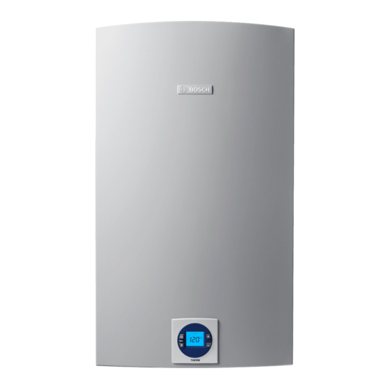
Appliance details Dimensions and minimum installation clearances Fig. 6 Dimensions [1] On/Off button [2] Reset button [3] Program key [4] Power ON or stand-by LED [5] LCD display [6] Up button [7] Down button C 1210ES/ESC – 6 720 644 887 (2022/04) -
Page 15: Installation Instructions
▶ The water heater must be installed by a qualified installer in accordance with these instructions. If improperly installed, a hazardous condition such as explosion or carbon monoxide poisoning could result. Bosch Thermotechnology Corp. is not responsible for improperly installed appliances. - Page 16 Installation instructions WARNING: The use of cellular core PVC (ASTM F891), cellular core CPVC, or Radel® (polyphenolsulfone) in non-metallic venting systems ▶ In areas where outside temperatures routinely come close is prohibited. to freezing, sealed combustion operation is required. Concentric termination or separate terminations for ▶...
- Page 17 Installation instructions Venting specifications Diam. Approved terminals 3 or 4 “T” terminal inches 90° elbow PVC Flue Cap*(ECAP321)Vertical terminations only 3" diameter only Concentric (196016) 3 or 4 “T” terminal inches 90° elbow PVC Flue Cap*(ECAP321)Vertical & horizontal terminations approved 3" diameter only Concentric (196016) Table 7 Venting specifications for intake and exhaust...
- Page 18 Installation instructions Minimum combustion air and exhaust pipe length The minimum exhaust pipe length is 1 foot (0.3m) of straight vent pipe. The minimum combustion air pipe length is one 90° Two 45° elbows are equal to one 90° elbow. Any elbow.
- Page 19 Installation instructions For this example, the maximum allowable combustion air pipe length is 10 feet. Calculation example for 4" venting: Exhaust System used Twin pipe Number of 90° elbows needed: Number of 45° elbows needed: Table 15 Calculation of example Max.
- Page 20 Installation instructions Required direct vent terminal clearances (twin pipe / concentric penetration) Fig. 9 1)2) 2)3) Canadian installations U.S. installations A Clearance above grade, veranda, porch, deck or 12 in. 12 in. balcony B Clearance to window or door that may be opened 36 in.
- Page 21 Installation instructions 1)2) 2)3) Canadian installations U.S. installations Clearance to service regulator vent outlet 36 in. Clearance to non-mechanical air supply inlet to building 36 in. 12 in. or the combustion air inlet to any other application K Clearance to mechanical air supply inlet 72 in.
- Page 22 Installation instructions Required other than direct vent terminal clearances (single pipe penetration) Fig. 10 1)2) 2)3) Canadian installations U.S. installations A Clearance above grade, veranda, porch, deck or balcony 12 in. 12 in. B Clearance to window or door that may be opened 36 in.
- Page 23 Installation instructions 1)2) 2)3) Canadian installations U.S. installations K Clearance to mechanical air supply inlet 72 in. 36 in. above if within 10 feet horizontally L Clearance above paved sidewalk or paved driveway located on 84 in. 84 in. public property M Clearance under veranda, porch deck or balcony 12 in.
- Page 24 Installation instructions 4.3.3 Vent configuration examples Below are approved examples of vertical and horizontal venting installations. Fig. 12 Horizontal venting installation (combustion air piping not shown) [1] Termination [2] Minimum above ground or normally expected snow accumulation level [3] Appliance [4] Elbow (note: minimum 1ft of straight vent pipe required) [5] Horizontal run ¼"...
- Page 25 Installation instructions Fig. 13 Horizontal venting system (concentric vent) Fig. 15 Horizontal venting system (single pipe penetration) [1] Exhaust [1] Exhaust pipe [2] Combustion air [2] Drain tee [3] Exhaust pipe [3] Intake pipe [4] Drain tee [LA] Minimum 4" [5] Intake pipe [LA] Minimum 1"...
- Page 26 Installation instructions ▶ Attach the flue gas exhaust accessory to the top of the unit ▶ Install 3" air intake pipe over the combustion air inlet (pos. 1) using the 4 screws and gasket provided. accessory. Fig. 16 Exhaust connection ▶...
- Page 27 Installation instructions External condensate drain installation WARNING: If an external condensate drain (installer supplied) must be installed (chapter 4.3.2), the following is recommended: ▶ Do not install condensate drain tubing in areas where it may • 1. Install condensate drain on a horizontal section of the freeze.
- Page 28 Installation instructions Note: The following solution is available only for 3" diameter venting. 6720608643-18.1V Fig. 22 Part nr 9301BFP Fig. 24 Installation [1] Good For this solution to be effective, the internal flapper must be [2] Better 100% closed when the water heater is not running. Refer to [3] Best figures 24 and 25 for preferred installation positions in the vent system.
- Page 29 Installation instructions 4.3.7 Fan speed adjustment ! IMPORTANT INFORMATION: Natural gas heaters with installation altitudes below 2,000 ft above sea level disregard this section. Installation adjustment: After installing the tankless water heater, the fan speed values for minimum power (P2) and maximum power (P1) may need adjustment due to variations in altitude and vent pipe length.
- Page 30 Installation instructions Natural Gas Liquid Natural Liquid propane propane Altitude (above Vent Total Minimum Minimum Maximum Maximum sea level) terminal equivalent power fan power fan power fan power fan vent length speed (P2) speed (P2) speed (P1) speed (P1) 0 - 2000 ft Concentric 3.5 - 39 ft For operation at...
- Page 31 Installation instructions Adjusting minimum power fan speed (P2) Adjusting maximum power fan speed (P1) To select fan speed: To select fan speed: ▶ Push power button to shut the water heater off. ▶ Push power button to shut the water heater off. ▶...
- Page 32 Installation instructions Attention residents of the Commonwealth of Massachusetts: In the Commonwealth of Massachusetts the following and2. Product approved side wall horizontally vented gas regulation went into effect on 12/30/2005:(a)For all side wall fueled equipment installed in a room or structure separate from horizontally vented gas fueled equipment installed in every the dwelling, building or structure used in whole or in part for dwelling, building or structure used in whole or in part for...
-
Page 33: Combustion Air Requirements
Installation instructions Combustion air requirements inside, it is not the manufacturer’s recommended installation method. Always install a 3 inch 90° elbow on the top of the CAUTION: combustion air inlet adaptor to prevent foreign objects from falling into the unit. If a single pipe installation is utilized, follow guidelines below for ▶... -
Page 34: Heater Placement And Clearances
Installation instructions ▶ 1. Locate the heater where venting, gas and plumbing connections are feasible and convenient. ▶ 2. The hot water lines should be kept short and insulated to Front cover should be removed (see instructions on page 12) in save energy. -
Page 35: Gas Piping & Connections
Installation instructions codes or, in the absence of local codes, the National Fuel Gas Code ANSI Z223.1/NFPA 54. In Canada: The Installation must conform to CGA B149 INSTALLATION CODES and/or local installation codes. WARNING: ▶ DO NOT connect to an unregulated or high pressure propane line or to a high pressure commercial natural gas line. - Page 36 Installation instructions Once connections are made, check for gas leaks at all joints. Apply some gas leak detection solution to all gas fittings. Bubbles are a sign of a leak. A combustible gas detector may also be used to detect for leaks. WARNING: ▶...
-
Page 37: Gas Line Sizing Tables For Natural Gas
Installation instructions 4.8.1 Gas Line Sizing Tables for NATURAL GAS For your convenience see below for an excerpt from gas line sizing tables for a single NG appliance. For details see the current NFPA Specified pipe lengths are for one C 1210 ES or ESC which have a maximum input rating of 225,000 BTUs. The gas supply system must be sized for the combined total maximum BTU/hr load requirements of all gas appliances running simultaneously. -
Page 38: Gas Line Sizing Tables For Lp Gas
Installation instructions 4.8.2 Gas Line Sizing Tables for LP GAS For your convenience see below for an excerpt from gas line sizing tables for a single LP appliance. Their intended use of is for pipe sizing between the 2nd stage (low pressure) regulator and the appliance. For details see the current NFPA 54 or NFPA 58. Specified pipe lengths are for one C 1210 ES or ESC which have a maximum input of 225,000. -
Page 39: Water Connections
Installation instructions Water connections NOTICE: ▶ This heater is not approved for preheated water applications exceeding 140°F (60°C). NOTICE: ▶ In applications where inlet water temperature can exceed 140°F (60ºC), a 3-way valve or mixing valve must be Fig. 32 Water filter installed before the appliance to prevent water exceeding 140°F (60°C) from entering the appliance. -
Page 40: Water Quality
For water analysis data call your local water department, or if on a well, have well water analyzed periodically. If water quality exceeds one or more of the values specified below, Bosch recommends consulting a local water treatment professional for water softening/conditioning options. - Page 41 Installation instructions Fig. 34 Filling the condensate trap at start up Filling the condensate trap after vent pipe installation After appliance has been out of use for a long time or after cleaning siphon, refill the condensate trap with water. Please proceed as follows: Fig.
-
Page 42: Domestic Hot Water Recirculation
Bosch Thermotechnology if further information is needed. a Bosch electric mini tank water heater. This schematic is for illustration only and must not be used for actual Installation 4.13 Space heating applications... - Page 43 (closed-loop setup). Bosch supports applications of combination DHW and space heating in an open loop configuration if plumbed similar to fig. 41. Use of a Bosch ▶ Ensure the primary pump is properly sized to provide tankless water heater in a combination DHW and space heating adequate flow for the system heat load.Ensure the primary...
-
Page 44: Measuring Gas Pressure
Installation instructions 6720644887-02.1V Fig. 41 Space heating diagram [1] Hot water outlet [18] Space heating zone [2] Cold water inlet [19] Zone controller [3] Pressure relief valve [20] Space heating pump [4] Gas supply [21] Expansion tank [5] Shut off gas valve [22] Pressure relief valve [6] Thermal expansion tank (as required) 4.14 Measuring gas pressure... - Page 45 Installation instructions Static Pressure Test ▶ Turn gas supply back on. ▶ Record static gas pressure reading in table 31. Operating Pressure Test ▶ Push power button to shut the water heater off. ▶ Push and hold the button. ▶ Turn power back on by pushing the power button ▶...
-
Page 46: Electrical Connections
Electrical connections Electrical connections Electrical power supply ▶ Remove the six screws from the back cover of the control unit, see fig. 45, pos. 2. WARNING: ▶ Check the fuses in the printed circuit board, see fig. 45, pos. 3. For safety reasons, disconnect the power supply cord to the heater before any service or testing is performed. -
Page 47: Description Lcd Display
Operation instructions Description LCD Display WARNING: ▶ Do not use any cleaning aggressive or corrosive agents to clean the window. Fig. 50 Locked condition indicator (only with remote control) Fig. 47 Power bar indicator (input) Fig. 51 Flame indicator Fig. 48 Temperature indicator Fig. -
Page 48: For Your Safety Read Before Operating Your Water Heater
Operation instructions For your safety read before operating your Temperature selection water heater To select hot water temperature: ▶ Press buttons in order to reach desired WARNING: temperature. ▶ If you do not follow these instructions exactly, a fire or explosion may result causing property damage, personal injury or loss of life. -
Page 49: Proper Location For Installing Your Heater
Operation instructions water heater operate identically. Contact your distributor to WARNING: order the remote control accessory. Modification of the water heaters interior control unit (Fig. 81, component 16) is required when installing the remote control with this heater. ▶ In applications where inlet water temperature can exceed 140°F (60ºC), a thermostatic or mixing valve must be installed before the appliance to prevent water exceeding 140°F (60°C) from entering the appliance. -
Page 50: Program Button
Maintenance and service Whenever LCD shows , the temperature setting cannot be adjusted because the appliance is in use by a user which already selected a different temperature. Appliance will be automatically unlock 5 minutes after closing hot water tap. Maintenance and service WARNING: Fig. -
Page 51: Winterizing For Seasonal Use
Maintenance and service pipe for blockage or debris. Inspect combustion air and Winterizing for seasonal use exhaust terminations for blockage or debris. The water heater must not be installed in a location where it may be exposed to freezing temperatures. If the heater must be WARNING: left in a space which is likely to experience freezing temperatures, all water must be drained from the heater. -
Page 52: Condensing Heat Exchanger Unit
The condensing heat exchanger unit must be checked once a necessary. year by a qualified and trained technician. If repairs are needed, the repairs should be done by a certified Bosch technician. C 1210ES/ESC – 6 720 644 887 (2022/04) -
Page 53: Adjusting Co2
Maintenance and service ▶ Insert CO analyzer probe into the measuring port. The tip of the probe should be in the center of the flue pipe (approx 1.5" inserted). Avoid air gaps between probe and It is important to inspect and properly replace the gaskets and measuring port as they can alter readings. -
Page 54: Program Values
Maintenance and service D. Returning to Service: range (%) Max. CO level (measured) 1. Return slotted screw cover to original position. 2. Reinstall Torx cover. 3. Remove CO analyzer probe and reinstall flathead screw LP Gas with gasket in exhaust collar. max. - Page 55 Runs secondary fan and primary fan when P9 is selected by depressing the “P” - button Cascading type This menu is only available when cascade mode is selected Contact Bosch Water Heating for details. Primary/ Secondary mode Table 35 Program values, factory default settings and ranges.
-
Page 56: Control Board Diagnostics
Maintenance and service Control board diagnostics Diagnostic menu 1. Push power button to shut the water heater off. 4th most recent error 2. Push and hold the button. 5th most recent error 3. Turn power back on by pushing the power button 4. -
Page 57: Troubleshooting
Troubleshooting Example: ▶ Select the sub-mode “C1”. Write the number that shows in the display. Calculation of number of working hours, ▶ Select the sub-mode “C2”. Write the number that shows in the display. Working hours After checking the sub-modes C0, C1 and C2, introduce the Number in H0 60 + values in a table as the example;... -
Page 58: Water Is Too Hot
Troubleshooting 8. With the power button pressed switch turned to OFF and by the heater. Wait 10 minutes and check all taps for water the power supply cord unplugged, remove the unit's front flow. There should be no water flowing. Any continuous cover (See fig. -
Page 59: Noisy Burner/Heater During Operation
Troubleshooting overpowered. This will shut down the burners because the 5. Lack of gas pressure. Inadequate gas pressure will cause hot water flow rate fell below the minimum flow rate the fuel-to-air mixture (CO ) to be out of adjustment. This required for activation. -
Page 60: Problem Solving
2. Check gas pressure. Low gas pressure may prevent the heater from reaching (Status message, not an error). desired output temperature. 3. Check supply voltage. It must be 120VAC and properly grounded. 4. Possible defective control unit call Bosch Water Heating for further instructions. C 1210ES/ESC – 6 720 644 887 (2022/04) - Page 61 81, page 81. 2. Check supply voltage. It must be 120VAC and properly grounded. 3. Possible defective component in fan or defective control unit call Bosch Water Heating for further instructions.
- Page 62 Turn off the water heater. Turn water heater back on and try resetting error code. Use the reset button ( to reset any error codes. 3. Possible defective control unit call Bosch Water Heating for further instructions. C 1210ES/ESC – 6 720 644 887 (2022/04)
- Page 63 GPM. Measure voltage at the gas valve wire plug connection. The voltage should measure 24VDC between the left pair of wires and 24VDC between the right pair of wires when the unit is operating. If voltage is not proper, contact Bosch Water Heating for further instruction.
-
Page 64: Electrical Diagram
Electrical diagram Electrical diagram Fig. 69 Electrical scheme [1] Inlet water temperature sensor [16] Power supply cord [2] Outlet water temperature sensor [17] Power connection [3] Backflow temperature sensor [18] Ignition electrodes [4] Cascading output connection [19] Ground post [5] Cascading input connection [20] Antifreeze kit connection [6] Ionization sensor [21] Fuse... -
Page 65: Sensor Resistance Charts
Sensor resistance charts Sensor resistance charts Fig. 70 Outlet sensor characteristics C 1210ES/ESC – 6 720 644 887 (2022/04) - Page 66 Sensor resistance charts Fig. 71 Inlet sensor characteristics C 1210ES/ESC – 6 720 644 887 (2022/04)
- Page 67 Sensor resistance charts Fig. 72 C 1210ES/ESC – 6 720 644 887 (2022/04)
- Page 68 Functional scheme Functional scheme IDLE Water flow > 0.5 gpm water tap See error code table (> 1.9 l/min) open? (see WF calc.) Fan speed = correct Ionization = off Appliance Temp. limiter = closed ready to start? Temp. sensors = ok Over heat protection = ok waiting Fan speed...
-
Page 69: Interior Components Diagram And Parts List
Interior components diagram and parts list Interior components diagram and parts list 13.1 Interior components Fig. 74 Components [1] Exhaust temperature sensor [12] Ignition electrodes [2] Condensing heat exchanger [13] Observation window [3] Heat exchanger [14] Backflow temperature sensor [4] Ionization sensor [15] Secondary air fan [5] Primary fan (Mixer) [16] Gas valve... - Page 70 Interior components diagram and parts list Fig. 75 Appliance overview C 1210ES/ESC – 6 720 644 887 (2022/04)
- Page 71 Interior components diagram and parts list 13.2 Components diagram 13.2.1 Group 1 Fig. 76 Components Diagram C 1210ES/ESC – 6 720 644 887 (2022/04)
- Page 72 Interior components diagram and parts list Item Description Reference Front cover 8 738 708 380 Cover shield 8 738 708 382 Trade mark badge 8 701 103 140 0 Cover screw 8 703 401 170 0 Combustion cover 8 700 506 300 0 Combustion cover gasket 8 704 701 084 0 Observation window...
- Page 73 Interior components diagram and parts list 13.2.2 Group 2 Fig. 77 Components Diagram C 1210ES/ESC – 6 720 644 887 (2022/04)
- Page 74 Interior components diagram and parts list Item Description Reference Heat exchanger 8 705 406 419 0 Heat exchanger top gasket 8 704 701 052 0 Condensing exchanger inlet 8 705 700 159 0 Overheat sensor (ECO) 8 707 206 204 0 Heat exchanger bottom gasket 8 704 701 054 0 Site window...
- Page 75 Interior components diagram and parts list 13.2.3 Group 3 Fig. 78 Components Diagram C 1210ES/ESC – 6 720 644 887 (2022/04)
- Page 76 Interior components diagram and parts list Item Description Reference Main burner (Natural Gas) 8 708 120 650 0 Main burner (LP Gas) 8 708 120 673 0 Burner gasket 8 704 701 087 0 Primary fan 8 707 204 081 0 Backflow temperature sensor 8 707 206 459 0 Washer...
- Page 77 Interior components diagram and parts list 13.2.4 Group 4 Fig. 79 Components Diagram C 1210ES/ESC – 6 720 644 887 (2022/04)
- Page 78 Interior components diagram and parts list Item Description Reference Gas valve 8 707 021 019 0 Pressure tapping 8 703 404 219 0 Washer 8 700 203 041 0 Pipe 8 718 221 063 0 Gas supply pipe 8 700 715 442 0 Gas valve washer 8 700 103 014 0 Gas filter...
- Page 79 Interior components diagram and parts list 13.2.5 Group 5 Fig. 80 Components Diagram C 1210ES/ESC – 6 720 644 887 (2022/04)
- Page 80 Interior components diagram and parts list Item Description Reference Water valve with engine 8 708 505 023 0 O-ring 8 700 205 147 0 Clip for water valve 8 716 102 607 0 Pipe 8 738 702 690 0 Clip 8 701 201 028 0 Clip 8 738 704 185 0...
- Page 81 Interior components diagram and parts list 13.2.6 Group 6 Fig. 81 Components Diagram C 1210ES/ESC – 6 720 644 887 (2022/04)
- Page 82 Interior components diagram and parts list Item Description Reference Control unit - C 1210 ES 8 738 708 390 Control unit - C 1210 ESC 8 738 708 392 Fuse T2.5A 1 904 521 342 0 Fuse T1.6A 8 700 609 008 0 Power supply cables 8 704 401 371 0 Power supply cord...
-
Page 83: Protecting The Environment
Protecting the environment Protecting the environment Installer Checklist to be completed by installer upon installation Packing The packing box may be fully recycled as confirmed by the recycling symbol Components Serial Number ___ ___ ___ ___ ___ ___ ___ ___ Many parts in the heater can be fully recycled in the end of the (8 digit serial number is product life. - Page 84 50 Wentworth Avenue Londonderry, NH 03053 Tel. 603-552-1100 Fax 603-965-7581 www.boschheatingandcooling.com U.S.A. Products manufactured by Bosch Thermotechnik GmbH Junkersstrasse 20-24 D-73249 Wernau www.bosch-thermotechnology.com Bosch Thermotechnology Corp. reserves the right to make changes without notice due to continuing engineering and technological advances.