Table of Contents
Quick Links
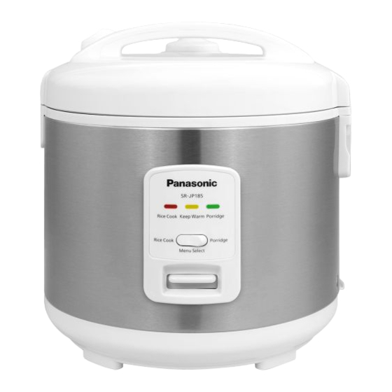
Electric Rice Cooker
SR-JP185WVA-US
Model No.
SR-JP185SWVA-US
SR-JP185WVA-CA
SR-JP185SWVA-CA
SR-JP185SBSR-ID
SR-JP185WSR-ID
SR-JP185TSH-SG
SR-JP185WSH-SG
SR-JP185WSW-SG
SR-JP185WSW-MN
SR-JP185SSK-MY
SR-JP185TSK-MY
SR-JP185WSK-MY
Destination:
USA, Canada, Indonesia, Singapore
(DBD), Singapore (RBD), Mongolia,
Malaysia
© 2015 Panasonic Manufacturing Malaysia Berhad (6100-K).
Unauthorized copying and distribution is a violation of law.
ORDER NO. PMMA150931CE
Table of Contents

Related Manuals for Panasonic SR-JP185WVA-US


Summary of Contents for Panasonic SR-JP185WVA-US
- Page 1 Model No. SR-JP185SWVA-US SR-JP185WVA-CA SR-JP185SWVA-CA SR-JP185SBSR-ID SR-JP185WSR-ID SR-JP185TSH-SG SR-JP185WSH-SG SR-JP185WSW-SG SR-JP185WSW-MN SR-JP185SSK-MY SR-JP185TSK-MY SR-JP185WSK-MY Destination: USA, Canada, Indonesia, Singapore (DBD), Singapore (RBD), Mongolia, Malaysia © 2015 Panasonic Manufacturing Malaysia Berhad (6100-K). Unauthorized copying and distribution is a violation of law.
-
Page 2: Table Of Contents
TABLE OF CONTENTS PAGE PAGE 1 Specifications ------------------------------------------------------3 2 Schematic Diagram-----------------------------------------------4 2.1. For 120V, 650W model. ----------------------------------4 2.2. For 220V, 400W model. ----------------------------------4 2.3. For 220V, 650W model. ----------------------------------5 2.4. For 230V, 650W model. ----------------------------------5 2.5. For 240V, 650W model. ----------------------------------6 3 Troubleshooting Guide------------------------------------------7 3.1. -
Page 3: Specifications
1 Specifications Model No. SR-JP185 USA / Canada AC 120V / 60Hz Indonesia / Singapore (RBD) / AC 220V / 50Hz Power Supply / Mongolia Rated Voltage Singapore (DBD) AC 230V / 50Hz Malaysia AC 240V / 50Hz Cooking 650 W Cooking (Indonesia) 400 W Keep Warm... -
Page 4: Schematic Diagram
2 Schematic Diagram 2.1. For 120V, 650W model. 2.2. For 220V, 400W model. -
Page 5: For 220V, 650W Model
2.3. For 220V, 650W model. 2.4. For 230V, 650W model. -
Page 6: For 240V, 650W Model
2.5. For 240V, 650W model. -
Page 7: Troubleshooting Guide
3 Troubleshooting Guide When receiving the rice cooker requiring repair, please ask the customer about the malfunctions (phenomena), and if necessary, you should also check the inner pot and spill-proof moisturizing cap. Power off first before checking the related components. Check the main unit according to the troubleshooting table below. -
Page 8: Test Method
4 Test Method 4.1. Pre-test setting Make sure that the inner pan set in the cooker and the power cord plugged into the wall socket. 4.2. Bubble test 1. Insert the pan into the cooker’s main body, and then turn it slightly clockwise and anti-clockwise to place the pan properly on top of the cast heater. -
Page 9: Disassembly And Assembly Instructions
5 Disassembly and Assembly Instructions 5.1. Replacing the switch assembly. Remove the base. • Place a rubber pad or similar thing under the rice cooker to prevent damage, and open the lid of the rice cooker, and place the bottom of the rice cooker upward, as shown in the diagram right. - Page 10 Remove the bracket • Remove the wiring on the switch assembly. • Remove the fixing screws (2 pcs) for the connecting rod bracket. • Push the bracket towards the temperature limiter, to remove the bracket. Remove the switch assembly. • Remove the fixing screws of the control baseplate. •...
-
Page 11: Replacing The Outer Lid
5.2. Replacing the outer lid. Remove the water collecting cup. • Remove the water collecting cup directly. Remove the hinge cover. • Remove the fixing screws for the hinge cover. • Remove the hinge cover using a screwdriver, as shown in the dia- gram. -
Page 12: Replacing The Body Assembly
5.3. Replacing the body assembly. Remove the hinge cover. • Disassemble the hinge cover by referring to Step (1-2) as shown in 5.2. Remove the switch assembly. • Remove the fixing screws for the hinge cover. • Disassemble the switch assembly by referring to Step (1-4) as shown in 5.1. Remove the Body Assembly. -
Page 13: Replacing The Temperature Limiter
5.5. Replacing the temperature limiter. Remove the base. • Disassemble the base by referring to Step (1) as shown in 5.1. Separate the temperature limiter from the switch assembly. • Gently bend the sheet connected to the switch assembly as shown in the diagram, and fold it into the slot shape at the connection of the switch assembly. -
Page 14: Replacing The Thermal Fuse
5.6. Replacing the thermal fuse. Remove the base, body assembly. • Disassemble the base by referring to Step (1) as shown in 5.1. • Refer to the method of replacing the body assembly to remove the body assembly. Disassemble the connectiong between the thermal fuse and the heating plate •... -
Page 15: Exploded View And Replacement Parts List
6 Exploded View and Replacement Parts List 6.1. Exploded View... -
Page 16: Packing View
6.2. Packing View... -
Page 17: Replacement Part List
6.3. Replacement Part List Important safety notice: Components identified by mark have special characteristics important for safety. When replacing any of these components, use only manufacturer’s specified parts. 6.3.1. Part List Safety Ref. Part No. Part Name & Description Remarks 3100790040 STEAM VALVE ASSY SR-JP185SSK/SR-JP185WSH/SR-JP185WSK/SR-JP185WSR/... -
Page 18: Screws
Safety Ref. Part No. Part Name & Description Remarks 1100000681 CAST HEATER ASSY SR-JP185TSH/SR-JP185WSH 1100000682 CAST HEATER ASSY SR-JP185SSK/SR-JP185TSK/SR-JP185WSK 1100000704 CAST HEATER ASSY SR-JP185WSW 1100010161 KEEP WARM HEATER SR-JP185SBSR/SR-JP185WSR 1100010185 KEEP WARM HEATER SR-JP185TSH/SR-JP185WSH 1100010193 KEEP WARM HEATER SR-JP185WSW 1100010181 KEEP WARM HEATER SR-JP185SWVA/SR-JP185WVA 1100010184...