Quick Links
Installation Instructions
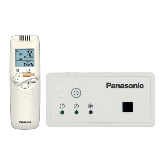
Wireless Remote Controller
CZ-RWST2U
Model No.
Safety Precautions
Read before installation
Read the Installation Instructions carefully
to install the remote controller correctly and
safely.
Be sure to read the Safety Precautions in
particular before installation.
After the installation is complete, perform
test operation to confirm that no abnormality
is present.
We assume no responsibility for accidents
or damages resulting from methods other
than those described in the installation
instructions or methods without using
specified parts.
Malfunctions that occurred due to the
unauthorised installation methods are not
covered by the product warranty.
Read the installation instructions supplied
with indoor units as well.
WARNING
This symbol refers to a hazard or unsafe
practice which can result in severe personal
injury or death.
CAUTION
This symbol refers to a hazard or unsafe
practice which can result in personal injury or
product or property damage.
85464369841010
1-4. Wiring for the Receiver
Wiring Diagram
Indoor unit
Terminals for RC
wiring
How to Connect the Wires
Connect the wires from the receiver to the terminals for RC wiring on the indoor unit.
(No polarity)
Installation Location for the Reciver
The wireless remote controllers use a very weak infrared light for its signal, which can result in the signal
not being received because of the following influences, so take care in where the unit is installed.
• Inverter or rapid-start type fluorescent lights (Models without glow lamps)
• Plasma display or LCD televisions
• Direct sunlight or other sources of bright light
Attention
Multiple wireless remote controllers cannot be used simultaneously for a single indoor unit.
Be careful not to connect cables to other terminals of indoor units (e.g. power source wiring terminal).
Malfunction may occur.
Do not bundle together with the power source wiring or store in the same metal tube. Operation error may
occur.
If noise is induced to the unit power supply, attach a noise filter.
*Wiring shown below is prohibited.
Wired RC
Receiver
1 2
1 2
RC wiring
R1 R2
R1 R2
Indoor unit
Indoor unit
Installation when setting Main/Sub for the remote controller and the receiver
Using 1 indoor unit
Installation
Receiver (Sub)
Wired RC (Main)
example
1 2
1 2
Terminals for
RC wiring
RC wiring
(field supply)
• No polarity
R1 R2
Indoor unit
After installation, according to the "Settings" section, set one to [Main] and the other to [Sub].
Setting the wired remote controller to [Main] is recommended.
Note
The remote controller and the receiver can be connected to any indoor unit for operation.
WARNING
• Turn off the circuit breaker of the units
before installation.
• Ask your dealer or professionals for
installation and electric work.
• This controller shall be installed in
accordance with National Wiring
Regulations.
• Connect and fix the specified cables for
wiring securely.
• Do not allow the connection to be exposed
to the external force of the cables.
• Choose an installation location that
sufficiently supports the weight of the
remote controller.
CAUTION
Do not use the remote controller at the
following locations.
• Location where condensation occurs
• Location where flammable gases, etc. may
leak
• Location where corrosive gases, etc. may
leak
• Location with lots of water or oil droplets
(including machine oil)
• Location where voltage fluctuation
frequently occurs
• Location where there is a machine
producing electromagnetic radiation
• Location where droplets of organic
solvents spread
• Location where acidic or alkaline solutions
or special sprays are frequently used
Do not operate with wet hands.
Do not wash with water.
- 1 -
Receiver PCB
CN001
1
2P white
2
1 2
R1 R2
Indoor unit
Receiver
Using more than 1 indoor unit
Receiver (Sub)
1 2
RC wiring (field supply)
• No polarity
R1 R2
R1 R2
R1 R2
Indoor unit
Indoor unit
Indoor unit
- 3 -
Wireless Remote
Controller
(1)
Before installing the receiver, see the
sections on "Wiring for the Receiver" and
"Setting Address Switches". Then check
the settings of the [S003] DIP switch on the
receiver's PCB.
* Remove the cover from the receiver when
performing the PCB settings.
Printed in Japan
DC0815-0
CV 6233317724
1 Open the air inlet grill on the side panel. Remove the 1 screw and move it toward the front
(in the direction of an arrow) to remove it. (Fig. A)
2 Wrap the tip of a slotted screwdriver with plastic tape and then insert it under the O-marked
surface of the cover, wiggling the cover free. (Fig. B) (Be careful not to scratch the panel.)
3 After passing the lead wire through the panel, install the receiver in the hole in the panel.
(The projecting parts of the receiver is held in the hole in the panel.)
4 Fasten the receiver's lead wire to the cable clip that is holding the wire from the louver motor.
(Fig. C)
5 Attach the side panel.
6 Put the receiver's lead wire together with other wires such as the louver motor wire, and fasten
them with the cable clip. (Fig. D)
Use the hole in the upper part of the wiring box to lead it in.
For more information about wiring and test runs, see the sections on "Wiring for the Receiver" and
"Test Operation" .
Fig. A
Panel
Fig. C
Wired RC (Main)
1 2
Receiver
R1 R2
Indoor unit
1-1. Part Names
(2) Emergency operation button
Starts/Stops emergency operation.
(3) Indication lamp
Indicates operation status.
1-2. Supplied accessories
Supplied accessories
Remote Control
AAA Size
Operating
Holder
Battery
Instructions
(1)
(2)
(1)
1-3. Settings
- 2 -
1-5. Installing the Receiver
Fig. B
Side panel
Plastic tape
Insert it under the
O-marked surface
of the cover.
Air inlet grill
Fig. D
Cable clip
- 4 -
(1) Light receiving section
Receives signals.
Wood Screw
Clamper
(2)
(1)
All set at OFF
when shipped
from the factory.
ON
Main/Sub selector
switch for remote
controllers (4)
Set its
OFF: Main ON: Sub
address
(1) to (3)
Slotted screwdriver
(Wrapped with plastic tape)
Cover
Cable clip
Panel

Related Manuals for Panasonic CZ-RWST2U


Summary of Contents for Panasonic CZ-RWST2U
- Page 1 1-1. Part Names (2) Emergency operation button Starts/Stops emergency operation. Installation Instructions (1) Light receiving section Receives signals. Wireless Remote Controller CZ-RWST2U Model No. Safety Precautions WARNING (3) Indication lamp • Turn off the circuit breaker of the units Read before installation Indicates operation status.
- Page 2 1-8. Self-diagnostics table and detected contents 1-6. Setting Address Switches The “Alarm Display” shown in the table below expresses the alarm contents displayed when the When more than 1 receiver is installed in the same room, setting addresses prevents wired remote controller is connected.