Table of Contents
Quick Links
Table of Contents

Related Manuals for AMGO MC-1200


Summary of Contents for AMGO MC-1200
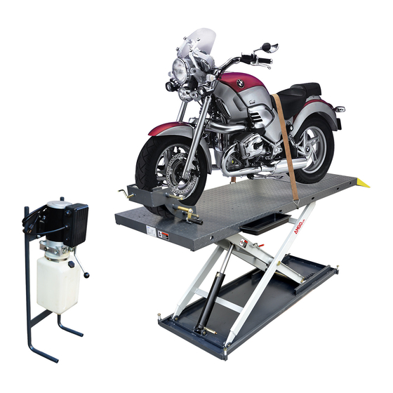
- Page 1 Motorcycle lift MC-1200...
-
Page 2: Table Of Contents
CONTENTS I. Product Features and Specifications…………………....…….1 II. Installation requirement...…………………………....……..…2 III. Steps of Installation...…………………………....…………..…3 IV. Exploded View………………………………………….....….…..8 V. Test Run…….……………………………………..…….…......11 VI. Operation Instruction.…………………………....…..…….…...12 VII. Maintenance……………………………………....….………..13 VIII. Trouble shooting.……………………………….…....……….…14 IX. MC-1200 parts list……..…………….………........…15... -
Page 3: Product Features And Specifications
I .PRODUCT FEATURES AND SPECIFICATIONS Motorcycle lift MC-1200: ● Hydraulic cylinders is designed and manufactured according to standard, utilizing imported seals Self-lubricating UHMW Polyethylene sliders and bronze bush ● Non-skid diamond platforms ● Automatic safety release system ● Optional: Width extension kit and platform extension kit ●... -
Page 4: Installation Requirement
II . INSTALLATION REQUIREMENT A. TOOLS REQUIRED Rotary Hammer Drill (Φ19) Ratchet Spanner with Socket :(28 # Screw Grease gun English Spanner (12") Hook Spanner (40~42mm) Pliers Wrench Set :(13 # # #... -
Page 5: Steps Of Installation
B. SPECIFICATIONS OF CONCRETE Specifications of concrete must be adhere to the specifications as following. Failure to do so may result in lift and/or vehicle falling. 1. Concrete must be thickness 4’’ minimum and without reinforcing steel bars,and must be dried completely before lift installation. 2. - Page 6 2. Open the parts box, check the parts according to the parts list (See Fig. 4). Fig.4 3. Open the parts bag, check the parts according to the parts list (See Fig. 5). Fig.5 B. Put the lift and control cabinet in good order and connect the oil hose, see Fig.6 51-1 51-2...
- Page 7 C. Install Electrical System 1. Schematic circuit diagram(Fig.7) Switch button SB(UP) Single Phase Fig.7 D. Fastening all the oil hose fittings, fill the power unit with right amount hydraulic oil ( in order to ensure the working life of hydraulic system and the machine reach the best performance, please fill in the No.46 high quality anti-wear hydraulic oil.
- Page 8 E. Install adjustable fixing device. See Fig.8 1.After connecting the wire, lift the motorcycle lift to a suitable height, install the adjustable fixing device according to below photo; 2. The adjustable fixing device can be chosen to install in different installed position of the platform.
- Page 9 F. Install width extension kit(optional).See Fig.9 Fig.9 G. Install platform extension kit(optional).See Fig.10 Note: Connect the holes on platform extension kit and the platform. Install the adjustable fixing device on the platform extension kit. Fig.10...
-
Page 10: Exploded View
IV. EXPLODED VIEW MODEL:MC-1200 Fig.11... - Page 11 Power unit stand Fig.12 Cylinder Fig.13...
- Page 12 Power unit 110V/60Hz/1 phase Fig.14 Illustration of hydraulic valve for power unit(110V/60Hz/1 phase) Microswitch Protective ring Relif valve Release valve Oil return port Handle Throttle Release valve Check valve Oil Outlet Fig.15...
-
Page 13: Test Run
V. TEST RUN 1. Install anchor bolts. see Fig.16 Install the anchor bolts to fix the machine after installing. Fig.16 Steps: Note: Twisting force is (150N.m)492lbf.ft for fixing the anchor screw , knock the anchor bolt into the ground at least 3-1/2’’ Drilling Tighten Bolting... -
Page 14: Operation Instruction
VI. OPERATION INSTRUCTIONS 1. Install well the oil hose between cylinder and power unit, connect well the wire, the motorcycle lift can be used. 2. Raise up the lift without vehicle for testing. 3. To lift vehicle Lower the lift to the lowest position, loosen the adjustable fixing device. Move the motorcycle to the platform, put the wheel in the adjustable fixing device, set well the motorcycle. -
Page 15: Maintenance
VII. MAINTENANCE SCHEDULE Monthly maintenance: 1. Lubricate all moving parts with lubricant. Fig.22 Fig.22 2. Check all connectors, bolts and pins to insure proper mounting. 3. Make a visual inspection of all hydraulic hoses/lines for possible wear or leakage Every six months: 1. -
Page 16: Trouble Shooting
VIII.TROUBLE SHOOTING TROUBLE CAUSE REMEDY 1. Button does not work 1. Replace button 2. Wiring connections are not 2. Repair all wiring connections Motor does not run in good condition 3. Motor burned out 3. Repair or replace motor 4. AC contactor burned out 4. -
Page 17: Mc-1200 Parts List
IX. PARTS LIST Note Item Part# Description QTY. 11720118 Platform 11720021 Cover plate of Platform 10217069 Hex bolt 11720123 Drive-in ramp 11720120 Outer scissor assy. 11720119 Inner scissor assy. 10610023 Sliding block 11720122 Pin for safety device 10206019 Snap ring 10720061 Socket bolts 11720125... - Page 18 Note Item Part# Description QTY. 10209034 Lock washer 10420043 Socket bolt 11720017 Adjusted shaft 11720016 Connecting plate for handle 10206023 Self locking nut 11720015 Fixed Bolt for operating handle 11720018 Operating handle 10206006 Washer 11720032 Adjustable fixing device 11720031 Active tube assy. 11720030 Adjustable frame 10420244...
- Page 19 Parts for cylinder Note Item Part# Description QTY. 20-1 11640030A Bore Weldment 20-2 11640031A Piston Rod 20-3 10201034 Bleeding Plug 20-4 11201033 Head Cup 20-5 10209078 Dust Ring 20-6 10201032 0-Ring 20-7 10201035 0-Ring 20-8 11201028 piston 20-9 10206069 0-Ring 20-10 10201031 0-Ring...
- Page 20 Parts for power unit, 11V/60Hz/1 phase Item Part# Description QTY. Note 81400533 Motor 81400363 Motor connecting shaft 81400362 Manifold block 10209149 Wash 81400276 End plug 81400259 Red plastic plug 85090142 Hex bolt Gear pump 81400280 Buffer valve 81400294 Washer 10209034 Socket bolt 81400295 O ring...
- Page 21 AMGO HYDRAULIC CORPORATION 1931 Jo Rogers Blvd, Manning, South Carolina, USA Tel: (803) 505-6410 Fax: (803) 505-6410 Manual Part No.: 72167602 Revision Date: 2018/10...