Table of Contents
Quick Links
Table of Contents

Related Manuals for AMGO SML-6


Summary of Contents for AMGO SML-6
- Page 1 SINGLE POST LIFT Model:SML-6...
-
Page 2: Table Of Contents
CONTENTS I. PRODUCT FEATURES AND SPECIFICATIONS ............... 1 II. INSTALLATION REQUIREMENT ................3 III. STEPS OF INSTALLATION ..................4 Ⅳ EXPLOEDED VIEW ....................15 V. TEST RUN ......................17 VI. OPERATION INSTRUCTIONS .................. 19 VII.MAINTENANCE SCHEDULE ..................20 VIII. TROUBLE SHOOTING ..................21 IX. -
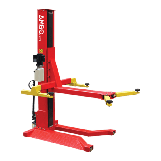
Page 3: Product Features And Specifications
· Super-symmetric arms design with 3-stages front arms and 2-stages rear arms. · Stackable and screwed type rubber pad. Fig.1 MODEL SML-2500 SPECIFICATIONS Minimum Lifting Lifting Lifting Overall Overall Model Style Motor Capacity Time Height Height Width Height 71-7/8”~ 108-7/8” 76-1/8” 4-1/8”~9- SML-6 Chain-drived 6,000 lbs 2.0HP 77-1/8” 1/4”... - Page 4 Arm Swings View Fig.2...
-
Page 5: Installation Requirement
II. INSTALLATION REQUIREMENT A.TOOLS REQUIRED Screw sets Level Bar Tape Measure(7.5mm) English Spanner(12″) Pliers Wrench set:(10 Socket Head Wrench:(4 # # # # # # # 、13 、14 、12 、5 、6 # # #... -
Page 6: Steps Of Installation
III. STEPS OF INSTALLATION A. Location of installation Check and insure the installation location (concrete, layout, space size etc.) is suitable for lift installation. B. Check the parts before assembly 1. Packaged lift and hydraulic power unit (See Fig. 4) Column Power unit Carriage... - Page 7 2. Take off the packaging on the machine Take off the packing rack. 3. Move aside the parts and check the parts according to the shipment parts list(See Fig.5 & 6) Fig.5 Shipment list Parts box (39) Fig.6 4. Check the parts of the parts bag according to the parts bag list (See Fig. 7) Fig.7...
- Page 8 C. Lay the base flat to the ground, confirm installation place according to the ground state, the main purpose is to save space. (See Fig.8) Fig.8 D. Install column and lift platform 1.Lay the column flat to the ground.(See Fig.9) Fig.9 Fig.9 2.Connecting oil hose of cylinder.
- Page 9 3.Fix column to the base plate. (See Fig.11) 4.Fix lifting platform to carriage.(See Fig.12) Fig.12 Fig.11...
- Page 10 E. Install cover of the safety device & retainer (See Fig.13) After install the retainer, cover the electric wires with take-up strap Screw with cup head bolt M6*8 Fig.13...
- Page 11 F. Install power unit and oil hoses (See Fig.14) Note: Tighten the oil hose fitting and power unit fitting to avoid oil leakage; Pay attention to the direction of power unit fitting. Tighter the screw with 19# wrench set after installing power unit fitting.
- Page 12 G. Install plastic cover(See Fig.15) Support plate for chain clip 链夹支撑板 Plastic cover go 塑胶挡板从此处穿过 through from here Fig.15...
- Page 13 H. Connect the power source according to the data on plate of power unit Note: For the safety of operators, the power wiring must contact the floor well Single phase motor (See Fig. 16) 1. Connecting the two power supply lines (active wire L and neutral wire N) to terminals of AC contactor marked L1, L2 respectively.
- Page 14 I. Install lifting arms Lowing the carriages down to the lowest position, fix hex screw M8*16 with spring washerφ8 and washerφ8 separately(see Fig.17) then tighten the screw (See Fig. 18). Hex screw M8*16 with spring washer φ8 and washer φ8. Lifting arm Fig.17 Tighten the screw...
- Page 15 J. Install wheel assembly First tighten the wheel assembly fixed square pipe by inner hex screw with spring washer φ12 and washer φ12(Fig.19). Put the wheel assembly into the fixed square pipe (Fig.20), insert the wheel assembly connecting board and fixed by elastic latch (Fig.21).
- Page 16 K. Tighten all the hydraulic fittings, and fill the reservoir with hydraulic oil. Note: In consideration of Hydraulic Power Unit’s durability and keep the equipment running in the perfect condition, please use Hydraulic Oil 46#. L. Using level to measure and adjust the column to be vertical (Fig.23). Use level to measure the column by front and side to make sure...
-
Page 17: Ⅳ Exploeded View
Ⅳ EXPLOEDED VIEW Model: SML-6 Fig.24... - Page 18 Cylinder exploded view Fig.25 Manual Power Unit 11V/60HZ/ 1 phase Fig.26...
-
Page 19: Test Run
Illustration of hydraulic valve for hydraulic power unit Power unit of 110V/60Hz/1PH(Fig.27) Oil return port Release valve Relief valve Oil output port Release handle Throttle valve Check valve Fig.27 V. TEST RUN 1. Adjust the lower speed (Fig.28) You can adjust the lower speed of the lift if needing: Loosen the Fixing Nut of the Throttle Valve, and then turn the Throttle Valve clockwise to decrease the lower speed, or counterclockwise to increase the lower speed. - Page 20 2. Test with load After finishing the above adjustment, test running the lift with load. Lift the lift in low position for several times first, make sure the lift can rise and lower without improper. And then test run the lift to top position completely. If there are anything improper, repeat the above adjustment.
-
Page 21: Operation Instructions
VI. OPERATION INSTRUCTIONS To lift vehicle 1. Keep clean of site near the lift; 2. Position lift arms to the lowest position; 3. To shortest lift arms; 4. Open lift arms; 5. Position vehicle beside of the lifting arm, car should at the other side of the column; 6. -
Page 22: Vii.maintenance Schedule
VII.MAINTENANCE SCHEDULE Monthly: 1. Re-torque the anchor bolts to 150 Nm; 2. Check all connectors, bolts and pins to insure proper mounting; 3. Lubricate cable with lubricant; 4. Make a visual inspection of all hydraulic hoses/lines for possible wear or leakage; 5. -
Page 23: Trouble Shooting
VIII. TROUBLE SHOOTING TROUBLE CAUSE REMEDY 1.Button does not work 1. Replace button 2.Wiring connections are not in good 2. Repair all wiring connection condition Motor does 3. AC contractor burned out 3. Repair or replace contractor not run 4. Motor burned out 4. -
Page 24: Parts List For Sml-2500
IX. PARTS LIST FOR SML-6 Item Part# Description QTY. Note 102611 Base 201020 90° Fitting for Cylinder 102606 Column 102608 Carriage 101002 Hex Bolt 201114 Lock Washer 209128 Washer 101001 Hex Bolt 420175 Hex Nut 071103 Power unit 102612 Outer Lifting arm left front(Inside) - Page 25 Item Part# Description QTY. Note 201090 Adjusting Shim 101013 Top Plate 206023 Self Locking Nut 217069 Hex Bolt 206079 Cap Head Bolt 101501 Parts box 203002 Power Side Safety Device 209007 Safety Spring 209009 Cap Head Bolt 209008 Safety Cover 206002 Safety Pin 206003A...
- Page 26 420029 Washer 102010 Wheel Assembly Connecting Pin 217048 Retainer Parts For Hydraulic Cylinder 65-1 207027 Piston Rod 65-2 207028 Piston 65-3 206069 O-Ring 65-4 620053 Support Ring 65-5 620054 Y-Ring 65-6 630027 O-ring 65-7 206071 Hex Nut 65-8 207029 Hydraulic Cylinder Adjustment Tube 65-9 217078 Dust Ring...
- Page 27 Filter 81400290 Motor 81400412 Run capacitor 81400086 Push button 10420070 AC connector 41030055 Cover of Motor Terminal Box 81400287 AMGO Sticker 71111106 81400296 Throttle valve body 81400459 O ring 10209069 Relief valve 81400266 Plug 81400284 81400452 Handle for release valve...
- Page 28 AMGO HYDRAULIC CORPORA TION 1931 Joe Rogers Blvd, Manning, South Carolina, Zip:29102 Tel: (803) 505-6410 fax: (803) 505-6410 72245801 09/2017...