Table of Contents
Quick Links
Table of Contents

Related Manuals for AMGO OH-9


Summary of Contents for AMGO OH-9
- Page 1 Original TWO POST LIFT Model: OH-9/OH-9H,OH-10/OH-10H...
-
Page 2: Table Of Contents
CONTENTS Product Features and Specifications ..........1 Installation Requirement .............4 Steps of Installation ……………………………………………………………………………….6 Exploded View ................25 Test Run ...................33 Operation Instruction ..............34 Maintenance ................35 Trouble Shooting ...............37 LIFT DISPOSAL ...................37... -
Page 3: Product Features And Specifications
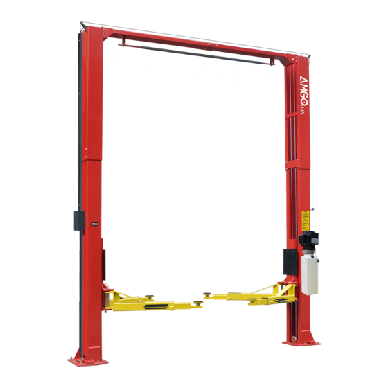
I. PRODUCT FEATURES AND SPECIFICATIONS CLEAR-FLOOR DIRECT-DRIVED MODEL FEATURES Model OH-9(H) , OH-10(H) (See Fig. 1) · Direct-drived design, minimize the lift spare parts and breakdown ratio · Dual hydraulic cylinders, designed and made as standards, utilizing oil seal in cylinder ·... - Page 4 Arm Swings View For Model OH-9(H) OH-10(H) Fig.2 Attention! Please make sure to place the arms in correct position before car drive in! Car in Fig.3...
- Page 5 Swing and extending the arms to the lifting point of vehicle Fig.4...
-
Page 6: Installation Requirement
II. INSTALLATION REQUIREMENT A. TOOLS REQUIRED Rotary Hammer Drill (Φ19) Carpenter’s ink marker Hammer Screw Sets Level Bar Tape Measure (7.5m) English Spanner (12") Pliers Ratchet Spanner with Socket (28 Socket Head Wrench (3 ... - Page 7 B. Equipment storage and installation requirements. The equipment should be stored or installed in a shady, normal temperature, ventilated and dry place. C. The equipment should be unload and transfer by forklift. Fig.6 D. SPECIFICATIONS OF CONCRETE (See Fig. 7) Specifications of concrete must be adhered to the specification as following.
-
Page 8: Steps Of Installation
Check and insure the installation location (concrete, layout, space size etc.) is suitable for lift installation. B. Use a carpenter’s ink marker line to establish installation layout of base-plate (See Fig.8). Model OH-9(H) and OH-10(H) Click a line 135” Fig. 8 C. - Page 9 5. Open the bag 1 of parts and check the parts according to parts box list (See Fig. 13). Fig. 13 6. Open the bag 2 of parts and check the parts according to parts bag list (See Fig. 14). OH-9/OH-9H OH-10/OH-10H Fig. 14...
- Page 10 This lift is designed with 2-Section columns. Adjust the height according to the ceiling height and connect the inner and extension columns. OH-9, OH-10: Not suitable for installation when the height of the workshop is less than 143-3/4"; only low setting installation for height between 143-3/4" - 151-1/2 ";...
- Page 11 1. High setting installation, choose the low holes of the outer column and install with the inner column. High setting Fig.16 2. Low setting installation, choose the high position holes of the outer column and install with the inner column. (See Fig.17). Low setting Fig.17...
- Page 12 F. Position columns (See Fig. 18) Position the columns on the installation layout of base-plate, Install the anchor bolts. Check the Columns plumpness with level bar, and adjusting with the shims if the columns are not vertical. Do not tighten the Anchor Bolts. Width between Columns: 112-1/4”...
- Page 13 G. Install overhead top beam 1. The hook on the top coupling assembly is hung on the outer column to lock the screws, and then the top beam is installed (See Fig. 19) Fig. 19...
- Page 14 2. Install the top beam, fix the anchor bolts. Tighten the anchor bolts with ratchet spanner with socket Note: Torque of Anchors is 150N.m Fig.20...
- Page 15 H. Installing the limit switch control bar and limit switch (See Fig. 21). Loosen screw of drive rod for adjustment, tighten the screw after adjustment Adjust drive rod of limit switch Limit switch connected Connect the blue wire to with cable terminal 11# on limit switch and terminal A1 on AC contactor of power unit...
- Page 16 I. Install safety device (See Fig. 22 & Fig. 23). Power-side safety device Fig.22 76A 76B Off-side safety device Fig.23...
- Page 17 J. Lift the carriages up and make them be locked at the same level (See Fig. 24). Fig. 24...
- Page 18 K. Install cables 1. Low setting cable connection (See Fig. 25). Low Setting installation holes Cable2 Cable1 Cable2 Fig. 25...
- Page 19 2.High setting cable connection 2.1. Cable pass through from the bottom of the carriages and be pulled out from the open of carriages, then screw the two cable nuts (See Fig. 26). High Setting installation holes Screw the two cable nuts Cable Connecting direction Cable connecting direction Fig.
- Page 20 2.2 Connecting cable for high setting (See Fig. 27). Cable 2 Cable 1 Cable 2 Fig. 27...
- Page 21 L. Install oil hose. (See Fig. 28). Wire holder Cylinder hose Power unit hose Fig.28 Following the above fig., first fix the cylinder hose with a wire holder, and then tie the power unit hose and the cylinder hose together with two cable ties...
- Page 22 M.Install protective cover. (Fig.29) Install M6*35 Screw 1.Put on M6*40 Screw; 2.Install protective cover, tighten the screws. Only for OH-9, OH-10 high setting Install protective cover and fix the oil hose Fig.29...
- Page 23 N. Install safety cable (See Fig. 30) Safety cable Wire cable across pulley bracket Install wire from Off-side safety device firstly Safety cable connect to power-side safety device Fig.30...
- Page 24 O. Install Protective Covers Note: Requirement of installation for oil hose and safety device. 1. Install Oil Hose. Note: Don’t cross the oil hose and safety cable together (See Fig. 31 & Fig. 32). Tie the hose and cable with a tape Safety Cable Oil Hose Wire Cable...
- Page 25 P. Install lifting arms and adjust the arm locks 1. Install the lifting arms (See Fig. 36). 2. Lowing the carriages down to the lowest position, then use the socket head wrench to loosen the socket bolt (See Fig. 37). Loosen the Bolt Use the 8 Socket Head Wrench...
- Page 26 R. Install electrical system Connect the power source according to the nameplate of the motor. Note: 1. Install the limit switch. 2. For the safety of operators, the lift must connect with the ground wire. 3. Pay attention to the rotary direction of the three phase motor. Single phase motor wiring (See Fig.
-
Page 27: Exploded View
IV. EXPLODED VIEW OH-9/OH-9H/OH-10/OH-10H Fig. 43... - Page 28 IX. PARTS LIST FOR OH-9 and OH-9H Item Part No. Description OH-9 OH-9H OH-10 OH-10H 10206019 Snap Ring φ19 10209012 Elastic latch φ3.2 10209128 Washer φ20 10209057B Bronze Bush for Pulley 11206020 Pulley 11206202 Power-side Inner Column 11279023 10209003 Hex Bolt M8*25 10209004 Rubber Ring φ8*20*3...
- Page 29 Item Part No. Description OH-9 OH-9H OH-10 OH-10H 11206046 Arm Lock Bar (right) 11217168 Arm pin assy. 10520023 Snap Ring φ38 10206190 Tool tray (Short) 11206191 Toe guard bar 10209019 Screw M6*16 10209018 Protective Rubber 11279004 Carriage Front right Arm...
- Page 30 Item Part No. Description OH-9 OH-9H OH-10 OH-10H Torsion spring φ2.5*120° 10217030 11217031 Driven safety control block 10217032 Wire cable connecting pin 10217033 Tension nut 10203778 Protective Cover L=1545 10206079 Cap Head Bolt M6*40 11206203 Offside Inner column 11279024 11209051B Stackable Adapter (1.5”) 11209052B Stackable Adapter (2.5”)
- Page 31 4.1 Rear arm assy. (10279011) explosive view Fig.44 Part no Name 10206048 Hex nut M10*30 10209039 Washer φ10 10209022 Washer φ10 11206049 Moon gear 11206192 Rear outer arm 10201149 Cap head bolt M8*12 11206193 Rear inner arm 4.2 Left front arm assy. (10279009) explosive view Fig.45 Part no Name...
- Page 32 4.3 Right front arm assy. (10279010) explosive view Fig.46 Part no Name 10206048 Hex nut M10*30 10209039 Washer φ10 10209022 Washer φ10 11206049 Moon gear 11206183 Front right outer arm 11206189 Front middle arm 10201149 Cap head bolt M8*12 11201049A Front inner arm 4.4 Cylinder (11217056) explosive view Fig.
- Page 33 Part list for cylinder Part no Name 30-1 10209069 O-ring 30-2 10209070 Bleeding Plug 30-3 10209071 Support Ring 30-4 10209072 Y-ring OSI 30-5 10209073 O-ring 30-6 11209074 Piston 30-7 10209075 O-Ring 30-8 11217076 Piston rod 30-9 11209077 Piston Rod Fitting 30-10 10209078 Dust wing...
- Page 34 Part list of power unit (220V/60HZ/single phase) Part no Name Part no Name Rubber pad Motor wiring cover 81400180 81400287 Starting capacitor AMGO label 81400130 71111104 Running capacitor Throttle valve 81400088 81400560 Screw with washer Relief valve 10420148 81400266 Capacitor cover...
-
Page 35: Test Run
V. TEST RUN 1. Adjustment of synchronous cable (See Fig. 50) Use wrench to hold the cable fitting, meanwhile using ratchet spanner to tighten the cable nut until the two cables are in the same tension. If the two vehicle carriages do not Synchronized Cable nut when lifting and lowering, please screw and tighten the cable nut on the lower side carriage. -
Page 36: Operation Instruction
5. Test with load After finishing the above adjustment, test running the lift with load. Run the lift in low position for several times firstly, make sure the lift can rise and lower synchronously, the Safety Device can lock and release synchronously. And then test run the lift to the top completely. -
Page 37: Maintenance
8. Continue to raise the lift slowly to the desired working height, ensuring the balance of vehicle; 9. Push release handle to lower lift onto the nearest safety. The vehicle is ready to repair. To lower vehicle 1. Be sure clear of around and under the lift, only leaving operator in lift area; 2. - Page 38 Oil cylinder maintenance: In order to extend the service life of the oil cylinder, please operate according to the following requirements. 1. Recommend to use N46 anti-wear hydraulic oil. 2. The hydraulic oil of the lifts should be replaced regularly during using. Replace the hydraulic oil 3 months after the first installation, Replace the hydraulic oil once a year afterwards.
-
Page 39: Trouble Shooting
VIII.TROUBLE SHOOTING TROUBLE CAUSE REMEDY 1. Button does not work 1. Replace button 2. Wiring connections are not in good 2.Repair all wiring connections condition Motor does not 3. Motor burned out 3. Repair or replace motor 4. Height Limit Switch is damaged 4. - Page 40 AMGO HYDRAULIC CORPORATION 1931 Joe Rogers Blvd, Manning, South Carolina, Zip: 29102 Tel: (803) 505-6410 72228004 Manual no: Fax: (803) 505-6410 Revised date:2021/02...